1
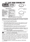
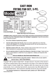
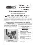
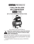
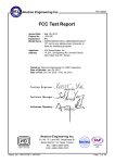
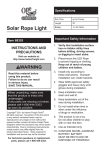
ROLLING
WORK SEAT
91495
ASSEMBLY INSTRUCTIONS
Visit our website at: http://www.harborfreight.com
Read this material before using this product.
Failure to do so can result in serious injury.
Save this manual.
Copyright© 2006 by Harbor Freight Tools®. All rights reserved. No portion of this
manual or any artwork contained herein may be reproduced in any shape or form
without the express written consent of Harbor Freight Tools. Diagrams within this
manual may not be drawn proportionally. Due to continuing improvements, actual
product may differ slightly from the product described herein. Tools required for
assembly and service may not be included.
For technical questions or replacement parts, please call 1-800-444-3353.
Revised Manual 09j
Specifications
Construction
Finish
Wheels
Seat Type
Overall Dimension
Tray Dimension
Overall Weight
Max. Weight Capacity
Heavy-Duty Tube/Formed Steel w/Polypropylene Plastic Tray
Green Powder Coated
Four 10” Dia. Pneumatic Tires w/Ball Bearing Wheels - 30 PSI
Bucket /Tractor Type - 13-1/4” L x 17” W x 7-1/2” H
33” L x 17-1/2” W x 23” H
17” L x 15-1/2” W x 3” D
30 Lbs.
300 Lbs.
Save This Manual
You will need the manual for the safety warnings and precautions, assembly instructions,
operating and maintenance procedures, parts list and diagram. Keep your invoice with
this manual. Write the invoice number on the inside of the front cover. Keep the manual
and invoice in a safe and dry place for future reference.
Safety Warnings and Precautions
WARNING: When assembling and using this product basic safety precautions
should always be followed to reduce the risk of personal injury and damage to
equipment.
Read all instructions before using this product!
1.
Keep work area clean. Cluttered areas invite injuries.
2.
Keep children away. Children must never be allowed in the work area. Do not let
children play with this product. This is not a toy.
3.
Dress properly. Do not wear loose clothing or jewelry as they can be caught in
moving parts. Protective, electrically nonconductive clothes and nonskid footwear
are recommended when working with this product. Wear restrictive hair covering
to contain long hair.
4.
Use eye and ear protection. Always wear ANSI approved impact safety goggles
when assembling this product.
5.
Do not overreach. Keep proper footing and balance at all times when assembling
this product.
6.
Replacement parts. When servicing, use only identical replacement parts. Use of
any other parts will void the warranty. Check for loose or worn parts before each
use.
Warning: The warnings, cautions, and instructions discussed in this instruction
manual cannot cover all possible conditions and situations that may occur.
It must be understood by the operator that common sense and caution are
factors which cannot be built into this product, but must be supplied by the
operator.
SKU 91495
For technical questions, please call 1-800-444-3353.
REV 07k
Page 2
Assembly Instructions
1. Assemble all parts on a smooth surface to avoid scratching. Sort and identify all parts.
Additional tools will be necessary to assemble the Rolling Work Seat. (Tools not included).
2. Matching up all the predrilled holes, attach the Tray Bracket (2) to the Frame (1), the Plastic
Tray (4) and the Reinforcing Plate (3) using the Screws (14), Small Washers (11), Lock
Washers (12), and Small Nuts (15). Tighten hardware. See Assembly Drawing, page 4.
Tray (4)
Wheel
(9)
Valve
Stem
Axle
(7)
Figure A
Figure B
Large
Washer
(10)
Nylon Axle
Nut (8)
3. Slide both Axles (7) into the Frame (1). Slide the Wheel (9) (be sure the valve stem is facing
out) and then a Large Washer (10) onto the Axle. Thread a Nylon Axle Nut (8) onto the end
of the axle and tighten, leaving enough space to permit the wheel to turn freely. Repeat for
all Wheels. See Figures A & B.
4. Be sure the Adjustment Lever (18) is screwed onto Seat Post (6). The Seat (5) is attached
to the Seat Post (6) with four Tapered Bolts (16) and Flange Nuts (17). Twist Seat (5) and
Seat Post (6) assembly into the Frame (1) clockwise. The threaded Post needs to be seen
from below the Frame. Insert the Cotter Pin (11) through hole in the Post. Spread open the
Cotter Pin (11). See Figures C & D.
Seat (5)
Seat Post
(6)
Frame (1)
Tapered
Bolt (16)
Flange
Nut (17)
Figure C
Adjustment
Lever (18)
Figure D
5. Loosen Adjustment Lever (18) to set the desired height. Adjust Seat height by rotating the
Seat in the Frame. Rotate Adjustment Lever (18) to lock seat post in position. The Adjustment
Lever (18) will prevent the Seat from lowering beyond the desired height. Before each
use, check the Seat (5) to make sure that the Seat is securely in place with all hardware
tightened down. Caution: Do not use the Rolling Work Seat on inclines. Do not load
Tray (4) with more than 5 lbs. Maximum weight for Seat (5) is 300 lbs. This product is
not for use by children.
REV 06e; 09f
SKU 91495
For technical questions, please call 1-800-444-3353.
Page 3
Caution: Be aware of dynamic loading!
DO NOT EXCEED THE RECOMMENDED PRODUCT WEIGHT CAPACITY. Doing so can
result in personal injury and/or damage to the product. If you sit down quickly onto the Work
Seat, it may create for a brief instant, an excess load, which may result in damage to the Work
Seat and/or personal injury.
Parts List
Part
1
2
3
4
5
6
7
8
9
10
11
12
13
14
15
16
17
18
Description
Frame
Tray Bracket
Reinforcing Plate
Plastic Tray
Seat
Seat Post
Axle
Nylon Axle Nut
Wheel
Large Washer
(8 mm ID flat)
Cotter Pin
Small Washer
Lock Washer
Screw
Small Nut
Tapered Bolt
Flange Nut
Seat Adjustment
Lever
Q’ty
1
2
2
1
1
1
2
4
4
Assembly Drawing
4
1
4
4
4
4
4
4
1
NOTE: Some parts are listed and shown for illustration purposes only and are not available individually as replacement parts.
PLEASE READ THE FOLLOWING CAREFULLY
THE MANUFACTURER AND/OR DISTRIBUTOR HAS PROVIDED THE PARTS DIAGRAM IN THIS MANUAL AS A
REFERENCE TOOL ONLY. NEITHER THE MANUFACTURER NOR DISTRIBUTOR MAKES ANY REPRESENTATION
OR WARRANTY OF ANY KIND TO THE BUYER THAT HE OR SHE IS QUALIFIED TO MAKE ANY REPAIRS TO THE
PRODUCT OR THAT HE OR SHE IS QUALIFIED TO REPLACE ANY PARTS OF THE PRODUCT. IN FACT, THE
MANUFACTURER AND/OR DISTRIBUTOR EXPRESSLY STATES THAT ALL REPAIRS AND PARTS REPLACEMENTS
SHOULD BE UNDERTAKEN BY CERTIFIED AND LICENSED TECHNICIANS AND NOT BY THE BUYER. THE BUYER
ASSUMES ALL RISK AND LIABILITY ARISING OUT OF HIS OR HER REPAIRS TO THE ORIGINAL PRODUCT OR
REPLACEMENT PARTS THERETO, OR ARISING OUT OF HIS OR HER INSTALLATION OF REPLACEMENT PARTS
THERETO.
SKU 91495
For technical questions, please call 1-800-444-3353.
Page 4