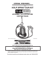
1
HVLP SPRAY GUN KIT
93305
ASSEMBLY and OPERATING
INSTRUCTIONS
Due to continuing improvements, actual product may differ slightly from the product described herein.
®
3491 Mission Oaks Blvd., Camarillo, CA 93011
Visit our Web site at http://www.harborfreight.com
To prevent serious injury,
Read and understand all warnings
and instructions before use.
Copyright© 2005 by Harbor Freight Tools® . All rights reserved. No portion of this manual or any
artwork contained herein may be reproduced in any shape or form without the express written
consent of Harbor Freight Tools.
For technical questions and replacement parts, please call 1-800-444-3353.
IMPORTANT: Before using for the first time, the spray gun must be cleaned
using a solvent based thinner. If not removed, the red oil used by the
manufacturer for testing and corrosion protection may contaminate paint.
IMPORTANT: The Spray Gun must be cleaned immediately after use.
Improper cleaning is a common reason for the Spray Gun not to work.
Contents
Specifications.................................................................................................. 3
Safety Warnings and Precautions................................................................. 3
Unpacking........................................................................................................ 5
Air Connection................................................................................................. 6
Control Layout................................................................................................. 6
A Comparison: Conventional versus HVLP Spray Guns............................. 7
Preparation...................................................................................................... 8
Fan Direction and Pattern Adjustment.......................................................... 8
Techniques..................................................................................................... 10
Maintenance....................................................................................................11
Parts List ....................................................................................................... 12
Assembly Diagram........................................................................................ 13
Troubleshooting............................................................................................ 14
Limited 1 Year Warranty................................................................................ 16
SKU 93305
For technical questions, please call 1-800-444-3353;
Troubleshooting section at end of manual.
Page 2
Specifications
Inlet PSI 30 - 43 PSI, 43 PSI MAX
Average Air Consumption 10 CFM @ 40 PSI
Paint Capacity2 Quart
Air Inlet
1/4” - 18 NPS
Nozzle Size.057”
Save This Manual
You will need the manual for the safety warnings and precautions, assembly instructions,
operating and maintenance procedures, parts list and diagram. Keep your invoice with this
manual. Write the invoice number on the inside of the front cover. Keep the manual and
invoice in a safe and dry place for future reference.
Safety Warnings and Precautions
WARNING: When using tool, basic safety precautions should always be followed to
reduce the risk of personal injury and damage to equipment.
Read all instructions before using this tool!
1.
Keep work area clean. Cluttered areas invite injuries.
2.
Observe work area conditions. Do not use machines or power tools in damp or wet
locations. Don’t expose to rain. Keep work area well lit. Do not use air tools in the
presence of flammable gases or liquids.
3.
Keep children away. Children must never be allowed in the work area. Do not let
them handle machines, tools, extension cords, or air hoses.
4.
Store idle equipment. When not in use, tools must be stored in a dry location to inhibit
rust. Always lock up tools and keep out of reach of children.
5.
Use the right tool for the job. Do not attempt to force a small tool or attachment
to do the work of a larger industrial tool. There are certain applications for which this
tool was designed. It will do the job better and more safely at the rate for which it was
intended. Do not modify this tool and do not use this tool for a purpose for which it was
not intended.
6.
Dress properly. Do not wear loose clothing or jewelry as they can be caught in
moving parts. Protective, electrically nonconductive clothes and nonskid footwear are
recommended when working. Wear restrictive hair covering to contain long hair.
7.
Use eye and ear protection. Always wear ANSI approved impact safety goggles.
Always wear an ANSI approved dust mask or respirator when using this Spray
Gun.
SKU 93305
For technical questions, please call 1-800-444-3353;
Troubleshooting section at end of manual.
Page 3
8.
Do not overreach. Keep proper footing and balance at all times. Do not reach over
or across running machines or air hoses.
9.
Maintain tools with care. Keep tools clean for better and safer performance. Follow
instructions for lubricating and changing accessories. Inspect tool cords and air hoses
periodically and, if damaged, have them repaired by an authorized technician. The
handle must be kept clean, dry, and free from oil and grease at all times.
10.
Disconnect air supply. Disconnect air hose when not in use, when changing
accessories, and during maintenance.
11.
Remove adjusting wrenches. Check that adjusting wrenches are removed from the
tool before attaching to the air source.
12.
Avoid unintentional starting. Be sure the trigger is in the Off position when not in
use and before attaching to the air source. Do not carry any tool with your finger on
the trigger, whether it is attached to the air compressor or not.
13.
Stay alert. Watch what you are doing, use common sense. Do not operate any tool
when you are tired.
14.
Check for damaged parts. Before using any tool, any part that appears damaged
should be carefully checked to determine that it will operate properly and perform its
intended function. Check for alignment and binding of moving parts; any broken parts
or mounting fixtures; and any other condition that may affect proper operation. Any part
that is damaged should be properly repaired or replaced by a qualified technician. Do
not use the tool if the trigger does not operate properly.
15.
Replacement parts and accessories. When servicing, use only identical replacement
parts. Use of any other parts will void the warranty. Only use accessories intended for
use with this tool. Approved accessories are available from Harbor Freight Tools.
16.
Do not operate tool if under the influence of alcohol or drugs. Read warning labels
if taking prescription medicine to determine if your judgement or reflexes are impaired
while taking drugs. If there is any doubt, do not operate the tool.
17.
Use proper size and type extension cord. If an extension cord is required for the
compressor, it must be of the proper size and type to supply the correct current to the
compressor without heating up. Otherwise, the extension cord could melt and catch
fire, or cause electrical damage to the compressor. Check your compressor’s manual
for the appropriate size cord.
18.
Maintenance. For your safety, maintenance should be performed regularly by a qualified
technician and the unit must be thoroughly cleaned out after every use. Improper
cleaning of the Spray Gun is a common reason for the Spray Gun to jam or not
perform properly.
19. Compressed air only. Never use combustible gas as a power source. Never exceed
the recommended operating pressure of the any of the parts (i.e. hoses, fittings, gun)
SKU 93305
For technical questions, please call 1-800-444-3353;
Troubleshooting section at end of manual.
Page 4
of the Sprayer system.
20.
Do not spray near open flames, pilot lights, stoves, heaters, the air compressor, or
any other heat source. Most solvents and coatings are highly flammable, particularly
when sprayed. Maintain a distance of at least 25 feet from the air compressor. If possible,
locate the air compressor in a separate room. Do not smoke while spraying.
21.
Read all of the information concerning coating products and cleaning solvents.
Chlorinated solvents (e.g. 1-1-1 Trichlorethylene and Methylene Chloride, also known
as methyl chloride) can chemically react with aluminum and may explode. Many paint
sprayers contain aluminum. If you have any doubt about potential chemical reactions,
contact the solvent or coating manufacturer.
22.
Materials used when painting or cleaning may be harmful or fatal if inhaled or
swallowed. Only use in an area with adequate ventilation. Use a respirator or mask
when painting or using cleaning solvents.
23.
Never release the sprayer lid while the cup is pressurized.
24.
Industrial applications must follow OSHA requirements.
25.
Never point a spray gun at a person or animal. Serious injury could occur.
26.
Spraying hazardous materials may result in serious injury or death. Do not spray
pesticides, acids, corrosive materials, fertilizers, and toxic chemicals.
27.
WARNING: The brass components of this product contain lead, a chemical known to
the State of California to cause birth defects (or other reproductive harm).
(California Health & Safety Code § 25249.5, et seq.)
Note: Performance of the compressor (if powered by line voltage) may vary depending
on variations in local line voltage. Extension cord usage may also affect tool performance.
Warning: The warnings, cautions, and instructions discussed in this instruction
manual cannot cover all possible conditions and situations that may occur. It must be
understood by the operator that common sense and caution are factors which cannot
be built into this product, but must be supplied by the operator.
Unpacking
When unpacking, check to make sure the product is intact and undamaged. If any parts
are missing or broken, please call Harbor Freight Tools at the number on the cover of this
manual as soon as possible.
SKU 93305
For technical questions, please call 1-800-444-3353;
Troubleshooting section at end of manual.
Page 5
Air Connection
For best service you should incorporate a regulator and inline filter, as shown in the diagram
above. Hoses, couplers, regulators, and filters are all available at Harbor Freight Tools.
Note: Compressor pumps discharge condensed water, oil, or other contaminants along with
the compressed air. Condensation causes “fish eyes” to appear in paint patterns. To avoid
this problem, install water/oil removal filters and controls (not included) as close to the Spray
Gun as possible. If run through the Gun, water and oil will cause damage.
1.
You will need to prepare a 1/4” air connector (sold separately) to connect to the air inlet
on the Spray Gun. First, wrap the 1/4” air connector (not included) with pipe thread
seal tape before threading it into the Air Inlet (36). Connect the Red Air Hose (41) to
the Air Outlet Connector (36). Attach the other end of the Red Air Hose (41) to the Air
Inlet (80) on the Gun.
2.
Set the air pressure on your compressor to 30-43 PSI. Do not exceed the maximum
air pressure of 43 PSI. Also, set the air pressure on the Air Regulator to 10-30 PSI, as
shown on the Gauge (38).
3.
Check the air connection for leaks and then disconnect the tool from the air source.
Control Layout
Air Adjustment Knob (73)
FIGURE 1
Pattern Control Knob (57)
Air Cap Set (45)
Fluid Control Knob (67)
Fluid Inlet
Trigger (78)
Air Inlet (80)
SKU 93305
For technical questions, please call 1-800-444-3353;
Troubleshooting section at end of manual.
Page 6
IMPORTANT: Before using for the first time, the spray gun must be cleaned
using a solvent based thinner. If not removed, the red oil used by the
manufacturer for testing and corrosion protection may contaminate paint.
IMPORTANT: The Spray Gun must be cleaned immediately after use.
Improper cleaning is a common reason for the Spray Gun not to work.
FIGURE 2
Fluid Outlet (39)
Air Inlet Connector (36)
Safety Valve (2)
Fluid Flow Knob (11)
Air Regulator (24)
Air Outlet Connector (36)
A Comparison: Conventional versus HVLP Spray Guns
Because conventional spray guns require a much higher air cap pressure to atomize
the paint than HVLP Spray Guns, conventional guns have lower transfer efficiencies
and more overspray.
This translates to a significant paint/material savings for HVLP guns, in addition to
making them more environmentally friendly.
To qualify as HVLP, the dynamic air pressure going in the Air Cap must be a maximum
of 10 PSI. The lower the air pressure, the less bounce back and overspray.
Note: Due to the viscosity of latex and other water-based paints, they are not
recommended for use with this or other HVLP (High Volume Low Pressure) sprayers.
See FIGURE 3 below.
Conventional
FIGURE 3
HVLP
SKU 93305
For technical questions, please call 1-800-444-3353;
Troubleshooting section at end of manual.
Page 7
IMPORTANT: Before using for the first time, the spray gun must be cleaned
using a solvent based thinner. If not removed, the red oil used by the
manufacturer for testing and corrosion protection may contaminate paint.
IMPORTANT: The Spray Gun must be cleaned immediately after use.
Improper cleaning is a common reason for the Spray Gun not to work.
Preparation
Note: Proper paint material mixture helps to ensure less problems. Be sure to follow the manufacturer’s directions. Most materials will spray readily if they are thinned properly.
General tips for Preparation:
1.
Mix and thin the paint/materials thoroughly according to the manufacturer’s
directions.
2.
Carefully strain the paint/material through a paint strainer or piece of cheese cloth.
3.
Remove (un-thread) the Cup (16) from the Unit. Fill the Cup (16) to approximately 3/4
full. Thread it back onto the unit. Connect the Fluid Hose (40) form the Fluid Outlet
(39) to the Fluid Inlet on the Spray Gun.
4.
Start the air compressor.
5.
To adjust the spray pattern, set up a piece of scrap material to practice on. While
practicing on the scrap material, check to see that the material you are spraying has
the appropriate consistency. If it appears to thin, add a very small amount of thinner
(not included). BE CAREFUL when thinning. Proceed slowly, adding very minimal
amounts. NEVER exceed the manufacturer’s thinning recommendations.
Fan Direction and Pattern Adjustment
Fan Direction
To change the direction of the fan from horizontal to vertical, loosen the Lock Ring and
turn the Air Cap (45) 90 degrees. After the adjustment, tighten the Lock Ring by hand.
See FIGURE 4 below.
Lock Ring
FIGURE 4
SKU 93305
Horizontal Fan
Air Cap
Vertical Fan
For technical questions, please call 1-800-444-3353;
Troubleshooting section at end of manual.
Page 8
IMPORTANT: Before using for the first time, the spray gun must be cleaned
using a solvent based thinner. If not removed, the red oil used by the
manufacturer for testing and corrosion protection may contaminate paint.
IMPORTANT: The Spray Gun must be cleaned immediately after use.
Improper cleaning is a common reason for the Spray Gun not to work.
Pattern Adjustment
Warning!! Never exceed the Maximum Inlet PSI of 43 PSI.
1.
Adjust the Gauge (38) pressure to 10-30 PSI using the Air Regulator (24). If you need
to reduce the air pressure for specific areas, adjust the Air Adjustment Knob (73).
To set the pattern size specific to the job, use the Pattern Control Knob (57) (see FIGURE 1 on page 6). By turning it counterclockwise (all the way open), the pattern will
flatten. Turn the Pattern Control Knob (57) clockwise for a round pattern.
See FIGURE 5 below.
2.
FIGURE 5
Flat/Open
3.
Round/Closed
Close the Fluid Control Knob (67) and fully open the Fluid Flow Knob (11). See FIGURE
1 on page 6.
4.
After setting up a piece of scrap material, squeeze the Trigger (78) in short bursts while
turning the Fluid Control Knob (67) counterclockwise and observe the spray patterns
until you see the pattern you want. Also, look at the pattern for consistency. Too much
air may cause the spray to come out too fine. Reduce the air pressure or allow more
material to come out by opening the Fluid Control Knob (67). If the spray appears too
thick (you see globs of paint), close down the Fluid Control Knob (67) slowly, checking
the mixture after each adjustment.
See FIGURE 6 below.
FIGURE 6
Too Coarse
(Tighten)
SKU 93305
Correct
Too Fine
(Loosen)
For technical questions, please call 1-800-444-3353;
Troubleshooting section at end of manual.
Page 9
IMPORTANT: Before using for the first time, the spray gun must be cleaned
using a solvent based thinner. If not removed, the red oil used by the
manufacturer for testing and corrosion protection may contaminate paint.
IMPORTANT: The Spray Gun must be cleaned immediately after use.
Improper cleaning is a common reason for the Spray Gun not to work.
Techniques
Note: Before spraying, mask all objects you do not want sprayed and lay cloths (not included)
on the floors.
1. Always keep the gun at right angles to the workpiece (See FIGURE 7). Pull the Trigger
(78) slowly and move the Spray Gun in parallel strokes to the object being painted.
Keep the distance from the object being painted at 6” to 9”. This may slightly differ
depending on the flow adjustment and the material being sprayed. Do not stop the
gun movement while spraying. If you stop the gun for even just a slight pause while
spraying, the paint will build up and run down the workpiece.
FIGURE 7
(Heavier coat on one
side, uneven coverage)
Incorrect
(Even coverage)
Correct (90o)
2.
To ensure you don’t allow paint to build up, start moving the Spray Gun before you
Squeeze the Trigger (78). When you are finished spraying, release the Trigger (78)
before you stop moving the Spray Gun. Doing so will eliminate distinct overlaps,
producing a blended (feathered) affect. See FIGURE 8 below.
Begin
Stroke
Squeeze
Trigger (78)
FIGURE 8
(Top View)
Release
Trigger (78)
End
Stroke
Note: The speed of the stroke, the adjustment of the Fluid Control Knob (67), and the distance
from the workpiece, will determine how much paint is being applied. To get the best
results, try to apply two thin coats of paint versus one thick coat.
3.
Clean out the gun thoroughly after EVERY use, according to the instructions
found on the next page.
SKU 93305
For technical questions, please call 1-800-444-3353;
Troubleshooting section at end of manual.
Page 10
Maintenance
Solvent Selection
Always follow the paint manufacturer’s recommendations for cleaning,
solvent type, and disposing of used solvent.
Note: Due to the viscosity of latex and other water-based paints, they are not recommended for use with this or other HVLP (High Volume Low Pressure) sprayers.
Oil Based Paints: Use mineral spirits.
If a flammable solvent needs to be used, adhere to the following:
1. Follow all of the solvent manufacturer’s clean up instructions and
safety precautions at all times.
2. Always flush the Spray Gun a full hose length from the air compressor.
3. If collecting flushed solvents into a metal container, transfer into a larger
nonmetal container, and flush the metal container.
4. Work far away from any ignition sources in a vapor free area.
After each use:
1.
Empty the Paint Cup (16) and clean it with the solvent.
2.
Fill the Paint Cup (16) with solvent and spray it through the Gun into a container, while
shaking the gun. Once the Paint Cup (16) is empty, repeat the process until the solvent
comes out clean.
Disconnect from the air source. After disconnecting, be aware that air pressure
may still remain in the Spray Gun. Point the Gun into the spent solvent container and
squeeze the Trigger again to make sure no air remains.
3.
Remove the Air Cap and soak it in solvent until it is clean. Use an old toothbrush and
toothpicks to remove any material. Do not use metal objects to clean the Air Cap
or you may damage the drilled passages. Inspect the fluid needle and make sure
it is not bent. If it is bent, have it replaced by a certified service technician.
Warning!! Do not immerse the Spray Gun Body in solvent!
4.
Use the appropriate solvent (depending on the material sprayed) to wipe down the Gun
body.
5.
Always lubricate the Spray Gun after cleaning. You may use a non-silicon oil or a light
lubricant on all threaded connections prior to storing the unit.
6.
Disposal: After cleaning your Spray Gun, properly dispose of your cleaning solutions
according to the solution manufacturer’s direction and local hazardous waste
standards.
SKU 93305
For technical questions, please call 1-800-444-3353;
Troubleshooting section at end of manual.
Page 11
Parts List
PartDescription
1
Handle
2
Safety Valve
3
Lock Nut
4
Spring
5
Valve
6
Valve Gasket
7
Valve Seat
8
Connector
9
Screw
10
Nut
11
Fluid Flow Knob
12
Spring
13
Cap
14
Suction Tube
15
Gasket
16
Cup
17
Rivet
18
Gasket
19
Tube
20
Screw
21
Spring
22
Rivet (Qty. 2)
23
E-clip
24*
Air Regulator
25*
Lock Nut
26*
Air Adjusting Seat
27*
Spring Seat
28*
Air Adjusting Seat
27*
Spring Seat
28*
Air Adjusting Screw
29*
Sealing Nut
30*
Sealing Gasket
31*
Valve Gasket
32*
Nut
33*
Needle Seat
34*
Air Needle
35*
Spring
36
Connector (Qty. 2)
37*
Gauge Seat
38
Gauge
39
Fluid Outlet Valve
PartDescription
40 Fluid Hose
41
Air Hose (Red)
42
Ring
43
Lock Ring
44
Gasket
45
Air Cap Set
46
Fluid Nozzle
47
Seat
48
Sealing Gasket
49
Packing Nut
50
Sealing Screw
51
Gasket
52
Gun Body
53
Needle
54
Needle Adapter
55
Spring
56
Fixed Screw
57
Pattern Control Knob
58
Rivet
59
Gasket
60
Sealing Screw
61
Adjusting Level
62
Valve Seat
63
Spring
64
Rivet
65
Air Adjusting Valve
66
O-ring
67
Fluid Control Knob
68
Gasket
69
E-clip
70
Fan Adjusting Screw
71
Fan Adjusting Stopper
72
O-ring
73
Air Adjustment Knob
74
Rivet
75
E-clip
76
Trigger Stud
77
Trigger Stud
78
Trigger
79
Fluid Connector
80
Air Inlet
*Parts 24 through 35 and 37 are available as a kit.
PLEASE READ THE FOLLOWING CAREFULLY
THE MANUFACTURER AND/OR DISTRIBUTOR HAS PROVIDED THE PARTS DIAGRAM IN THIS
MANUAL AS A REFERENCE TOOL ONLY. NEITHER THE MANUFACTURER NOR DISTRIBUTOR MAKES
ANY REPRESENTATION OR WARRANTY OF ANY KIND TO THE BUYER THAT HE OR SHE IS QUALIFIED TO MAKE ANY REPAIRS TO THE PRODUCT OR THAT HE OR SHE IS QUALIFIED TO REPLACE
ANY PARTS OF THE PRODUCT. IN FACT, THE MANUFACTURER AND/OR DISTRIBUTOR EXPRESSLY
STATES THAT ALL REPAIRS AND PARTS REPLACEMENTS SHOULD BE UNDERTAKEN BY CERTIFIED
AND LICENSED TECHNICIANS AND NOT BY THE BUYER. THE BUYER ASSUMES ALL RISK AND LIABILITY ARISING OUT OF HIS OR HER REPAIRS TO THE ORIGINAL PRODUCT OR REPLACEMENT PARTS
THERETO, OR ARISING OUT OF HIS OR HER INSTALLATION OF REPLACEMENT PARTS THERETO.
SKU 93305
For technical questions, please call 1-800-444-3353;
Troubleshooting section at end of manual.
Page 12
41
40
80
Assembly Diagram
NOTE: Some parts are listed and shown for illustration purposes only and are not available
individually as replacement parts.
REV 01/07
For technical questions, please call 1-800-444-3353;
SKU 93305
Troubleshooting section at end of manual.
Page 13
Troubleshooting
Spray Pattern Diagnosis
The Patterns below resemble symptoms of spray pattern problems. Please refer to
the accompanying possible problems if you are experiencing similar difficulties. The
solution to each problem follows the problem in parentheses.
Problem 1:
1. The Pattern Control Knob (57) is partially closed. (Open Pattern Control Knob (57).)
2. The material is too thick. (Thin material according to the manufacturer’s instructions.)
3. The air pressure is too low. (Increase air pressure. Make sure air pressure feeding into
the pot is within the proper range (30-43 PSI) & air pressure as shown on the Gauge (38)
is within the proper range (10-30 PSI).)
Problem 2:
1. High air pressure. (Reduce air pressure at gun.)
2. Not enough fluid. (Increase fluid.)
3. Pattern Control Knob (57) open too much. (Partially close Pattern Control Knob (57).)
Problem 3:
1. Air Cap plugged. (Clean the Air Cap.)
2. Air cap loose or dirty seat. (Clean and tighten.)
3. Dried material on fluid tip. (Use a nonmetallic point to clean the Air Cap.)
Problem 4:
1. Dirt on one side of the fluid tip. (Clean the fluid tip.)
2. Holes on one side of the Air cap are plugged. (Clean the Air cap with a nonmetallic
point.)
If the steps above do not solve the problem or if the repairs involved are too
complex, contact a qualified technician.
SKU 93305
For technical questions, please call 1-800-444-3353.
Page 14
Troubleshooting (continued)
Problem
Sputtering Spray
Will Not Spray
Overspray
Fluid Tip Leakage
Air Leaking from Air Cap
Cause
1. Low material level
2. Cup tipped too far
3. Clogged Air Vent
4. Loose fluid inlet connections
5. Dry or loose fluid needle
Packing Nut
6. Loose/damaged fluid tip/seat
1. No pressure at gun
2. Fluid control not open enough
3. Fluid too thick
1. Improper application speed
2. Improper distance from
workpiece
3. Too much pressure
1. Dirty tip
2. Tight Packing Nut
3. Broken fluid needle spring
4. Worn or damaged tip
1. Dirty air valve/seat
2. Sticking air valve
3. Damaged air valve spring
4. Worn/damaged air valve/seat
5. Bent valve stem
Fluid Leaking from Packing Nut 1. Packing Nut loose
2. Packing worn or dry
Solution
1. Refill
2. Hold upright
3. Clean vent hole
4. Tighten
5. Lubricate and/or tighten
6. Adjust or replace
1. Check air hoses
2. Open fluid control
3. Thin fluid or increase pressure
(within Maximum range)
1. Move moderately and parallel
2. Adjust distance
3. Reduce air pressure
1. Clean
2. Loosen Packing Nut
3. Replace
4. Replace tip and/or needle
1. Clean
2. Lubricate
3. Replace
4. Replace
5. Replace
1. Tighten without restricting
2. Replace or lubricate (nonsilicone)
If the steps above do not solve the problem or if the repairs involved are too
complex, contact a qualified technician.
SKU 93305
For technical questions, please call 1-800-444-3353.
Page 15
90 Day Warranty
Harbor Freight Tools Co. makes every effort to assure that its products meet high quality
and durability standards, and warrants to the original purchaser that this product is free
from defects in materials and workmanship for the period of 90 days from the date of purchase. This warranty does not apply to damage due directly or indirectly, to misuse, abuse,
negligence or accidents, repairs or alterations outside our facilities, criminal activity, improper installation, normal wear and tear, or to lack of maintenance. We shall in no event
be liable for death, injuries to persons or property, or for incidental, contingent, special or
consequential damages arising from the use of our product. Some states do not allow the
exclusion or limitation of incidental or consequential damages, so the above limitation of
exclusion may not apply to you. This warranty is expressly in lieu of all other warranties, express or implied, including the warranties of merchantability and fitness.
To take advantage of this warranty, the product or part must be returned to us with transportation charges prepaid. Proof of purchase date and an explanation of the complaint must
accompany the merchandise. If our inspection verifies the defect, we will either repair or
replace the product at our election or we may elect to refund the purchase price if we cannot readily and quickly provide you with a replacement. We will return repaired products at
our expense, but if we determine there is no defect, or that the defect resulted from causes
not within the scope of our warranty, then you must bear the cost of returning the product.
This warranty gives you specific legal rights and you may also have other rights which vary
from state to state.
3491 Mission Oaks Blvd. • PO Box 6009 • Camarillo, CA 93011 • (800) 444-3353
SKU 93305
For technical questions, please call 1-800-444-3353;
Troubleshooting section at end of manual.
REV 08c
Page 16