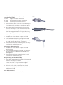
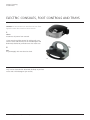
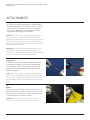
1
® EMAX 2 PLUS SYSTEM High speed performance and power in a variety of applications This publication is not intended for distribution in the USA. USER’S MANUAL TABLE OF CONTENTS INTRODUCTION Anspach Electric System 2 Indications and Contraindications 3 Warnings and Cautions 4 Technical Specifications 5 Glossary of Symbols 10 OPERATING INSTRUCTIONS eMax 2 Plus Operating Instructions 12 ATTACHMENTS AND DISSECTION TOOL ASSEMBLY Standard Attachments and Dissection Tool Assembly 20 CARE AND MAINTENANCE Otologic Curved Micro (OCM) Attachment and Otologic Curved Micro (OCM) Burr Support Sleeves 25 Minimal Access Attachment and Dissection Tool Assembly 26 microSaws and Small Attachments Assembly 28 Perforator Driver 31 Inspection and Maintenance 32 Cleaning Instructions 36 Manual Cleaning 37 Manual Pre-Cleaning Before Mechanical /Automated Cleaning 41 Mechanical / Automated Cleaning Following Manual Pre-Cleaning 47 Lubrication49 Sterilization50 Loading Configuration 52 Troubleshooting53 Ordering Information 54 Image intensifier control Anspach eMax 2 Plus System User’s Manual DePuy Synthes Companies 1 ANSPACH ELECTRIC SYSTEM HIGH SPEED PERFORMANCE AND POWER IN A VARIETY OF APPLICATIONS DePuy Synthes Power Tools DePuy Synthes Power Tools manufactures pneumatic and electric high speed performance instruments and attachments to meet the specific needs of both surgeon and staff. While the advanced design of these instruments provides performance and reliability, they also allow for effortless assembly, meeting the needs of both surgeon and staff for the most demanding applications. No tools are required to assemble dissection tools or attachments. All DePuy Synthes Power Tools instruments are manufactured to conform to rigorous quality standards to provide dependable performance. eMax 2 Plus EMAX 2 Plus System The EMAX 2 Plus System operates up to 80,000 rpm. It offers variable speed, bi-directional operation, minimal noise levels, and an optional hand control. It is a high performance system that highlights minimal vibration performance, thermal energy management, and high reliability for neurosurgeons, otologists, neurotologists, skull base surgeons, and spinal surgeons. Warning: Before using any of the Anspach High Speed Electric Systems, it is imperative that all individuals working with the system read this operating manual. The surgeon is responsible for learning the proper techniques in the use of this system, as improper use may cause injury. Spine surgery If you have any questions after reading this manual, please contact your Depuy Synthes Sales Representative. 2 DePuy Synthes Companies Anspach eMax 2 Plus System User’s Manual Neurosurgery and Otologic surgery INDICATIONS AND CONTRAINDICATIONS Indications The Anspach eMax 2 Plus High Speed Electric System is intended for cutting and shaping bone including spine and cranium. The Anspach eMax 2 Plus High Speed Electric System is composed of the eMax2Plus Handpiece model; Electric Consoles models SC2100, SC2101, and SC2102; Foot Control models E-FP, E-FP-DIR, E-FP-DIR/IRR, EPLUS-FP, EPLUS-FP-NS; Hand Controls EMAX2-HC and E-HC. Contraindications None. Anspach eMax 2 Plus System User’s Manual DePuy Synthes Companies 1 WARNINGS AND CAUTIONS Warnings Irrigation is necessary for proper operation. Use a gentle tapping motion or side-to-side motion and let instrument do cutting. Surgeon is responsible for learning proper techniques in use of equipment; improper use may cause serious injury to user or patient or damage to system. Do not use excessive force. Instrument operator and all operating room personnel must wear eye protection. Dissection tools are disposable and intended for single patient use only. Do not resterilize and / or reuse dissection tools. Visually inspect for damage before using; do not use if damage is evident. Forceful side loading of dissection tool may cause fracture of dissection tool, which may cause injury. Use standard protocol for disposal of sharp instruments. Do not use if the product sterilization barrier or its packaging is compromised. Continuous extreme cutting at or near stalling conditions will quickly overheat handpiece. Do not use, or discontinue use of powered equipment exhibiting excessive temperatures that can cause patient injury (necrosis) and / or user discomfort. Do not operate in an explosive flammable environment. Use of damaged or improperly maintained power equipment and / or misused powered equipment can result in excessive temperatures. Portable and Mobile RF communications equipment can affect Medical Electrical Equipment. Use caution to avoid cutting or tearing gloves while handling dissection tools. Dissection tools must be adequately retained within attachment to prevent distal migration, which may cause injury. Confirm attachment is proper size for dissection tool and that it is secure. Gently pull on dissection tool shaft to ensure it is fully seated and properly installed. Only cut visible areas unless an image intensifier is utilized. Delicate structures in proximity to dissection must be thoroughly protected to prevent injury. Maintain firm control of instrument at all times. Do not bend or use as a lever. Do not modify ground or power cord. Do not allow liquid into console. Use of accessories or cable other than those provided by DePuy Synthes Companies, and specified for the electric system in use, may result in increased emissions or decreased immunity. Do not use in oxygen rich environment. Do not modify. Modifications could result is loss of electrical safety. Dispose of items contaminated with body fluids with other biohazardous waste. At end of life, recycle or dispose of device in accordance with local and national regulations. No modification of this equipment is allowed. To avoid the risk of electric shock, this equipment must only be connected to a supply mains with protective earth. Precautions United States Federal law restricts this device to sale by or on order of a physician or other licensed healthcare provider. Do not step on, set equipment on, pinch, kink, clamp, or otherwise occlude handpiece hose during use. Do not use accessories other than those provided by DePuy Synthes Companies and specified for use with Anspach systems. Do not operate handpiece without an attachment and the corresponding dissection tool. Use care to protect hose when handling, cleaning, and during system use. To ensure equipment operates as designed, read and follow manufacturer’s instructions. Do not engage safety mechanism while handpiece is running; doing so makes safety mechanism inoperable. Damage to hose can cause leaking, rupture, or other related failures. 4 DePuy Synthes Companies Anspach eMax 2 Plus System User’s Manual TECHNICAL SPECIFICATIONS eMax 2 Plus Handpiece Specifications Speed: 10,000 – 80,000 rpm Handpiece / hose Length: 3.81 m (12.5 ft) Outside housing (diameter): 18.8 mm (.74 in) Length of housing: 127 mm (5 in) Handpiece weight: 104 g (3.7 oz) Handpiece Hose Weight: 0.59 kg (1.29 lbs) Foot Pedal (E-FP, E-FP-DIR, E-FP-DIR/IRR) Specifications Size: 26.7 cm 16.5 cm 14.7 cm (10.5 in 6.5 in 8.5 in) Weight: 2.0 kg (4.41 lbs) Cord: 3.66 m (12 ft) in length Fluid Ingress Protection: IPX8 Console (SC2000, SC2100, SC2101, SC2102) Specifications Electrical: Primary: 100 – 240VAC, 50/60 Hz, 250 VA Class I: Protective Earth Fluid Ingress Protection: IPX0 Type B: Applied Part Continuous Operation Environmental Conditions Temperature Operating: 18° – 30°C (65° – 85°F) Transportation and Storage: – 40 ° – 70°C (– 40° – 158°F) Mechanical: Size: 31.115 cm 14.6 cm 32.7 cm (12.25 in 5.74 in 12.87 in) Weight: 6.25 kg (13.77 lbs) The device complies with the following standards: IEC 60601-1:2005: + CORR. 1 (2006) + CORR. 2 (2007), EN 60601-1:2006 +A11:2011, ANSI / AAMI ES606011:2005, CAN / CSA-C22.2 No.60601-1:08, (3rd Edition) Medical electrical part 1: General requirements for basic safety and essential performance. Relative Humidity Operating: Transportation and Storage: Atmospheric Pressure Operating: Transportation and Storage: 30 – 70% 10 – 95% 70 – 106 kpa, 0.7 – 1.06bar Not applicable Patent Information For patent information go to: www.DePuy.com / patentmarking Additional Information To isolate the device from the mains supply, remove the power cord. All specifications are subject to change. With regard to electrical shock, fire, mechanical hazards, this ETL classified device conforms to AAMI STD ES60601-1 and is certified to CSA STD C22.2 No.60601-1 This device complies with applicable EEC directives. Anspach eMax 2 Plus System User’s Manual DePuy Synthes Companies 5 Technical Specifications Table 1: Emission The Anspach eMax 2 Plus High Speed Electric System is composed of the eMax 2 Plus Handpiece model; Electric Consoles models SC2100, SC2101, and SC2102; Foot Control models E-FP, E-FP-DIR, E-FP-DIR/IRR, EPLUS-FP, EPLUSFP-NS; Hand Controls EMAX2-HC and E-HC. Guidance and manufacturer’s declaration – electromagnetic emissions The Anspach High Speed Electric System is intended for use in the electromagnetic environment specified below. The customer or the user of the Anspach High Speed Electric System should assure that it is used in such an environment. Emission test Compliance Electromagnetic environment – guidance RF emissions Group 1 The Anspach High Speed Electric System uses RF energy only for its internal function. Therefore, its RF emissions are very low and are not likely to cause any interference in nearby electronic equipment. Class A The Anspach High Speed Electric System is suitable for use in all establishments, other than domestic establishments and those directly connected to the public low-voltage power supply network that supplies buildings used for domestic purposes. CISPR 11 RF emissions CISPR 11 Harmonic emissions Class A IEC 61000-3-2 Voltage fluctuations / flicker emissions Complies IEC 61000-3-3 6 DePuy Synthes Companies Anspach eMax 2 Plus System User’s Manual Table 2: Immunity (all devices) Guidance and manufacturer’s declaration – electromagnetic immunity The Anspach High Speed Electric System is intended for use in the electromagnetic environment specified below. The customer or the user of the Anspach High Speed Electric System should assure that it is used in such an environment. Immunity test standard U T (25 cycles) IEC 60601 test level Compliance level Electromagnetic environment – guidance Electrostatic discharge (ESD) IEC 61000-4-2 ±6 kV contact ±6 kV contact ±8 kV air ±8 kV air Floors should be wood, concrete or ceramic tile. If floors are covered with synthetic material, the relative humidity should be at least 30%. Electrical fast transient / burst ±2 kV for power supply lines ±1 kV for input / output lines Mains power quality should be that of a typical commercial or hospital environment. IEC 61000-4-4 ±2 kV for power supply lines ±1 kV for input / output lines Surge ±1 kV line to line ±1 kV line to line Mains power quality should be that of a typical commercial or hospital environment. IEC 61000-4-5 ±2 kV line to earth ±2 kV line to earth Voltage dips, short interruptions and voltage variations on power supply lines <5 % UT (>95 % dip <5 % UT (>95 % dip in UT) for 0.5 cycle in UT) for 0.5 cycle IEC 61000-4-11 40 % UT (60 % dip in UT) for 5 cycles 40 % UT (60 % dip in UT) for 5 cycles 70 % UT (30 % dip in UT) for 25 cycles 70 % UT (30 % dip in UT) for 25 cycles Mains power quality should be that of a typical commercial or hospital environment. If the user of the Anspach High Speed Electric System requires continued operation during power mains interruptions, it is recommended that the Anspach be powered from an uninterruptible power supply or a battery. <5 % UT (>95 % dip <5 % UT (>95 % dip in UT) for 5 s in UT) for 5 s Note: U T is the a.c. mains voltage prior to application of the test level. Power frequency (50 / 60 Hz) magnetic field 3 A / m 3 A/m Power frequency magnetic fields should be at levels characteristic of a typical location in a typical commercial or hospital environment. IEC 61000-4-8 Anspach eMax 2 Plus System User’s Manual DePuy Synthes Companies 7 Technical Specifications Table 3: Immunity (not life-supporting devices) Guidance and manufacturer’s declaration – electromagnetic immunity The Anspach High Speed Electric System is intended for use in the electromagnetic environment specified below. The customer or the user of the Anspach High Speed Electric System should assure that it is used in such an environment. Immunity test standard IEC 60601 test level Compliance level Electromagnetic environment – guidance Conducted RF 3 Vrms 3V IEC 61000-4-6 150 kHz to 80 MHz Radiated RF 3 V/m Portable and mobile RF communications equipment should be used no closer to any part of the Anspach High Speed Electric System, including cables, than the recommended separation distance calculated from the equation applicable to the frequency of the transmitter. IEC 61000-4-3 80 MHz to 2.5 GHz 3 V/m Recommended separation distance d = 1.2 √P d = 1.2 √P 80 MHz to 800 MHz d = 2.3 √P 800 MHz to 2.7 GHz Where P is the maximum output power rating of the transmitter in watts (W) according to the transmitter manufacturer and d is the recommended separation distance in metres (m). Field strengths from fixed RF transmitters, as determined by an electromagnetic site surveya a should be less than the compliance level in each frequency range.b Interference may occur in the vicinity of equipment marked with the following symbol: Note 1: At 80 MHz and 800 MHz, the higher frequency range applies. Note 2: These guidelines may not apply in all situations. Electromagnetic propagation is affected by absorption and reflection from structures, objects and people. aField strengths from fixed transmitters, such as base stations for radio (cellular/cordless) telephones and land mobile radios, amateur radio, AM and FM radio broadcast and TV broadcast cannot be predicted theoretically with accuracy. To assess the electromagnetic environment due to fixed RF transmitters, an electromagnetic site survey should be considered. If the measured field strength in the location in which the Anspach High Speed Electric System is used exceeds the applicable RF compliance level above, the Anspach High Speed Electric System, or the device which contains it, should be observed to verify normal operation. If abnormal performance is observed, additional measures may be necessary, such as reorienting or relocating the device containing the Anspach High Speed Electric System. bOver the frequency range 150 kHz to 80 MHz, field strengths should be less than 3 V/m. 8 DePuy Synthes Companies Anspach eMax 2 Plus System User’s Manual Table 4: Recommended separation distances (not life-supporting devices) Recommended separation distances between portable and mobile RF communications equipment and the Anspach High Speed Electric System The Anspach High Speed Electric System is intended for use in the electromagnetic environment in which radiated RF disturbances are controlled. The customer or the user of the Anspach High Speed Electric System can help prevent electromagnetic interference by maintaining a minimum distance between portable and mobile RF communications equipment (transmitters) and the Anspach High Speed Electric System as recommended below, according to the maximum output power of the communication equipment. Rated maximum output power of transmitter Separation distance according to frequency of transmitter 150 kHz to 80 MHz 80 MHz to 800 MHz 800 MHz to 2.5 GHz d = 1.2 √P d = 1.2 √P d = 2.3 √P 0.01 12 cm 12 cm 23 cm 0.1 38 cm 38 cm 73 cm 1 1.2 m 1.2 m 2.3 m 10 3.8 m 3.8 m 7.3 m 100 12 m 12 m 23 m W For transmitters rated at a maximum output power not listed above, the recommended separation distance d in metres (m) can be estimated using the equation applicable to the frequency of the transmitter, where P is the maximum output power rating of the transmitter in watts (W) according to the transmitter manufacturer. Note 1: At 80 MHz and 800 MHz, the separation distance for the higher frequency range applies. Note 2: T hese guidelines may not apply in all situations. Electromagnetic propagation is affected by absorption and reflection from structures, objects and people. Anspach eMax 2 Plus System User’s Manual DePuy Synthes Companies 9 GLOSSARY OF SYMBOLS 30 Sec ON / 30 Sec OFF Duty Cycle of the DRIVER Company Logo Direction of rotation Direction of rotation for lock position Located on the Foot Pedal switch this indicates a change state (on / o ff) for the Console Irrigation System Located on the Foot Pedal switch this indicates a change of rotational direction for the Handpiece SAFE Located on the Handpiece this indicates SAFE position of the knurl knob to the desired location IndicatesSAFE setting, position, or location SAFE Indicates setting, position, or location SAFE SAFE SAFE CUTTER RUN ADJUST SAFE Indicates the drill tip SAFE SAFE TUBE CUTTER CUTTER RUN CUTTER RUN ADJUST RUN CUTTER ADJUST TUBE ADJUST RUN CUTTER TUBE CUTTER TUBE ADJUST RUN RUN CUTTER TUBE ADJUST ADJUST RUNTUBE TUBE CUTTER ADJUST CUTTER CUTTER RUN TUBE CUTTER RUN RUN ADJUST RUN ADJUST ADJUST CUTTER TUBE TUBE ADJUST TUBE RUN TUBE ADJUST SAFE SAFE SAFE CUTTER RUN CUTTER ADJUST CUTTER exposure RUN RUN TUBE ADJUST ADJUST Symbol with yellow background: CAUTION: Refer to accompanying documentation SAFE SAFE SAFE TUBE CUTTER TUBE RUN ADJUST SAFE SAFE Indicates the attachmentCUTTER setting, refer TUBE RUN CUTTER to MA-D20 and MA-DRIVER section in ADJUST RUN CUTTER this document for further details TUBE ADJUST RUN SAFE SAFE F TUBE ADJUST CUTTER TUBE RUN ADJUST CUTTER TUBE RUN ADJUST Indicates position or location F R F or location F Indicates position F F R FR IndicatesF action of rotation and position R F R and Release for Secure (LOCK) R F F (UNLOCK) R R FR F R Direction of R Rrotation R TUBE CUTTER RUN ADJUST 0.5 TUBE 1.6 4.8 CUTTER 6.4 8.0 RUN ADJUST 3.2 4.8 6.4 8.0 1.6 3.2 F F F R F R R FR SAFE 2.4 2.4 SAFE 1.6 6.4 8.0 Direction of rotation Located on the Console this indicates 2.4 Motor or Handpiece unit 1.6 2.4 1.6 2.4 0.5 1.6 2.4 Located on 0.5 the Console this indicates 1.6 3.2 Foot Control activation F F R Located on the Console this indicates R F Hand Control activation R F R Located on the Console this indicates Forward (Clockwise rotation when FR 2.4 2.4 2.4 2.4 2.4 4.8 6.4 8.0 0.5 3.2 4.8 2.4 1.6 1.6 Direction of rotation for lock position 1.6 Consult Operating Instructions 2.4 1.6 1.6 1.6 1.6 4.8 4.8 0.5 3.2 0.5 6.4 4.8 8.04.8 6.43.2 0.5 3.2 6.4 8.04.8 TUBE 4.8 8.0 6.4 3.2 6.4 8.0 0.5 8.0 4.8 0.5 6.4 3.2 8.0 0.5 3.2 4.8 3.2 4.8 6.4 0.5 4.86.4 8.0 3.2 6.48.0 8.0 4.8 0.5 1.6 3.2 0.5 3.2 SAFE 1.6 1.6 0.5 6.4 TUBE 0.5 8.0 2.4 3.2 0.5 AC Power Source SAFE 2.4 2.4 6.4 0.5 8.0 0.5 3.2 3.24.8 0.5 6.4 4.8 8.0 3.2 6.4 8.0 4.8 0.5 6.4 8.0 3.2 2.4 3.2 0.5 4.8 6.4 3.2 8.0 4.8 6.4 8.0 2.4 1.6 2.4 1.6 2.4 1.6 2.4 1.6 2.4 1.6 looking at Handpiece from proximal 4.8 0.5 2.4 6.4 1.6 end) 8.0 3.2 R F Located on the Console this indicates 4.8 6.4 8.0 0.5 R 2.4 Reverse 3.2 (Counterclockwise rotation 1.6 4.8 6.4 8.0 when looking at Handpiece from proximal0.5 end) Located on the Foot Pedal switch this indicates a change of rotational direction for the Handpiece Located on the Foot Pedal switch this indicates a change state (on / off) for the Console Irrigation System Located on the Console this indicates a change state (on /off) for the Console Irrigation System 3.2 SAFE SAFE 11 DePuy Synthes Companies Anspach eMax 2 Plus System User’s Manual SAFE CUTTER 4.8 Revolution per Minute 6.4 8.0 R Located on the Console this indicates a change of irrigation rate for the Console Irrigation System Located on the Console this indicates a change of rotational speed rate for the Handpiece Temperature Limits Equipotential post location Found on the Console ON / OFF Single Use Only (A.K.A. Do Not Reuse) CAUTION: Refer to accompanying documentation Keep Dry (A.K.A. Protect from Moisture) Sterile unless damaged or open United States Federal law restricts this device to sale by or on the order of a physician or other licensed health-care provider CE Mark (A.K.A. CE Mark [notified body number], Conformité Européenne) Meaning: Device complies with applicable EEC Directives Located on the Console Irrigation Pump 2.4 1.6 this indicates a possible finger pinch point Lock (Run) 0.5 2.4 2.4 3.2 1.6 4.8 6.4 Located on the Console 8.0 2.4 1.6 Irrigation Pump these symbols 0.5 are not used by the user since 3.2 0.5 4.8 the pump is self adjusting to 6.4 3.2 8.0 the Irrigation Tube diameter 4.8 1.6 1.6 2.4 1.6 2.4 2.4 1.6 Unlock (Load) 0.5 0.5 0.5 3.2 3.2 0.5 4.8 4.8 3.2 6.4 6.4 8.0 8.0 4.8 3.2 6.4 4.8 8.0 6.4 8.0 6.4 8.0 Transmitter Interference may occur in the vicinity of equipment marked with this symbol. Type B Electrical Equipment Reference Number (A.K.A. Item Number, Catalog Number, Part Number) Product warranty is void if seal is damaged or removed. Lot (A.K.A. Lot Number, Batch Number, Batch Code) DO NOT DISPOSE OF IN HOUSEHOLD WASTE Serial Number Instrument System Key Use By Date (A.K.A. Expiration Date, 00/0000 Expiry) Manufacturer EM eMax 2 Plus Latex-free Certification Products not made with natural rubber latex. Authorized European Union Representative Sterilized Using Irradiation Anspach eMax 2 Plus System User’s Manual DePuy Synthes Companies 11 EMAX 2 PLUS OPERATING INSTRUCTIONS The system console houses the electrical components that provide power, control, and cooling functions to the eMax 2 Plus handpiece. It provides the user control for all system functions via an integral touch pad face panel. The system console has connections for the eMax 2 Plus handpiece, foot controls, AC power inlet and the main power switch. The eMax 2 Plus High Speed Handpiece operates continuously at speeds up to 80,000 rpm. Power Switch (Rear of Unit) Face Panel Handpiece Connector Port Foot Control Connector Port Back of System Console IV Pole Mount Power Switch AC Power Inlet* Swivel (270°) Attachment Connection Knurled Knob Protective Cap Handpiece Housing Handpiece Hose Handpiece Hose Connector *If two foot controls or two handpieces are connected upon startup of console it will default to Foot Control 1 and/or Handpiece 1. ** “Port” LED on console face panel does not illuminate when this accessory is connected to console. Note: The hose length shown above is shorter than the actual length for easier viewing. Hose length is approximately 12 feet. • Power cord provides means to disconnect from the mains. • Position equipment in such a manner that provides access to the rear of the system in order to disconnect from mains. 11 DePuy Synthes Companies Anspach eMax 2 Plus System User’s Manual System Assembly 1.Plug the hospital grade AC power cord into the AC power inlet on the back of the console. Plug the opposite end of the power cord into a standard, hospital grade grounded wall outlet. Connect to supply mains with protective earth only. 2.Insert foot control cord connector into Foot Control 1 connector port. (A second foot control cord may be connected into Foot Control 2 connector port on applicable consoles.) Foot control cord connector is keyed. Align foot control cord connector with port on front of console. Do not push foot control cord connector into console connector port when out of alignment. 3.Plug handpiece hose connector into Handpiece 1 connector port located on front of console. (A second handpiece could be connected into Handpiece 2 connector port on applicable consoles.) Handpiece hose connector is keyed. Align handpiece hose connector with connector port on front of console. Do not push handpiece hose connector into console connector port when out of alignment. 4.Activate console by depressing power switch located on the back of the console to the “I” position. Appropriate Face Panel Light Emitting Diodes (LED) illuminate, and a beep sounds. 5.For operating instructions see Console Face Panel Operation and Foot Control Operation below. Note: Handpiece is fully functional at this time. Warning: Before first use clean and sterilize as indicated. Anspach eMax 2 Plus System User’s Manual DePuy Synthes Companies 11 eMax 2 Plus Operating Instructions Operating Instructions Upon startup, console is set to operate handpiece in forward (clockwise when viewed from the proximal end of the Handpiece) direction at maximum speed and display reads 80,000 RPM. System operation, including optional irrigation, can be controlled from console face panel. On applicable consoles LED’s on face panel correspond to connector ports on connector panel. System operation can also be controlled by several available foot control options and an optional hand control. Console Face Panel Operation 1.To increase or decrease speed of handpiece, depress blue arrows located on console face panel. Speed increases and decreases in 10,000 RPM increments. Each LED will indicate the max RPM: 10 = 10,000 RPM 20 = 20,000 RPM 30 = 30,000 RPM 40 = 40,000 RPM 50 = 50,000 RPM 60 = 60,000 RPM 70 = 70,000 RPM 80 = 80,000 RPM 2.To change direction, depress “R” or “F” arrow located on console face panel. Console beeps once, indicating handpiece direction has changed. Direction can only be changed when handpiece is not running. A series of three beeps indicates console is set to operate handpiece in reverse/counterclockwise direction. LED on console face panel located to left of “F” indicates forward direction. LED located to left of “R” indicates reverse direction. 3.Optional: To activate irrigation, depress “Irrigation” button on face panel. LED illuminates. To control flow of irrigation, depress arrows located to right of irrigation button on face panel. Increase Speed Decrease Speed LED: Forward F: Forward R: Reverse LED: Reverse Hand Control LED: Foot Control #1 LED: Foot Control #2 Irrigation Increase / Decrease Foot Control Irrigation ON /OFF Note: Depressing simultaneously the Irrigation Increase and Decrease buttons will display the Console Software version as a two digit number. For example: XY this to be interpreted as Software Version X.Y. On Consoles with no Irrigation (SC2102) the buttons are not marked but are located in the same location which are detectable by feel. 11 DePuy Synthes Companies Anspach eMax 2 Plus System User’s Manual Foot Control Operation Certain optional foot controls have direction and irrigation control switches. 1.See Step 2 of Console Face Panel Operation to set operational direction of handpiece. 2.Optional: Depress “Foot” button on face panel to activate Foot Control 1, depress again to activate Foot Control 2. Only one foot control may be active at a time. Directional Control Switch Irrigation Control Switch EPLUS-FP or EPLUS-FP-NS Foot Control Note: Handpiece is fully functional at this time. 3.Press on foot control pedal to start handpiece. Increase pressure on pedal to increase speed of handpiece and release pressure on pedal to decrease speed of handpiece. 4.Optional: To change direction of handpiece, depress Directional Control Switch located on top left of foot control for a minimum of one second. When direction changes, a single beep will sound and LED on console face panel indicates direction of rotation. Direction can only be changed when handpiece is not running. 5.Optional: To activate irrigation, depress Irrigation Control Switch on top right of foot control for a minimum of one second and then step on center of foot control pedal. Upon activation, LED on face panel illuminates; irrigation pump and handpiece start. E-FP Foot Control Directional Control Switch E-FP-DIR /IRR Foot Control Anspach eMax 2 Plus System User’s Manual DePuy Synthes Companies 11 eMax 2 Plus Operating Instructions Hand Control Assembly and Operation Optional hand control attachment for handpiece allows user to control operation with a lever attached to handpiece. Warnings: • Do not expose handpiece to magnets (such as laying handpiece on magnetic drapes) when in hand control mode, as handpiece operation may occur. • It is recommended that a craniotome not be used in conjunction with Hand Control. Excessive rotational force on hand control may move it resulting in handpiece shutting down. Dimple Inser t to L o ck Notch lines up with Dimple eMax 2-HC 1.Upon console start-up Hand Control is OFF. LED is not illuminated. 2.Rotate handpiece until small dimple at proximal end (hose end) of handpiece faces up. Slide hand control over distal end of handpiece such that notch on hand control slides over dimple at proximal end (hose end) of handpiece. Slide Hand Control onto handpiece until secure. 3.To activate Hand Control, depress “Hand” button on console face panel. This deactivates Foot Control; Hand Control LED on face panel illuminates. 4.To prevent inadvertent operation, ensure silver lever on Hand Control is fully inserted in “Lock” position. 5.Extend silver lever from “Lock” position for operation. 6.Apply pressure on Hand Control to operate handpiece. Note: Handpiece is fully functional at this time. 7.To deactivate Hand Control, depress “Foot” button on console face panel. To remove hand control from handpiece, slide towards distal end of handpiece and remove. 11 DePuy Synthes Companies Anspach eMax 2 Plus System User’s Manual Optional Irrigation Assembly and Operation (Excludes SC2102) 1.Upon start-up Irrigation is OFF. LED is not illuminated. 2.Depress the button located on the right side of the console to eject pump head. 3.Insert IV pole into bracket on back of console. 4.Hang irrigation bag onto IV Pole. 5.To activate, depress the “Irrigation” button on the face panel. LED illuminates. 6.To control flow of irrigation, depress arrows located to right of irrigation button on face panel. 7.Irrigation can also be activated from certain optional Foot Controls (see Step 5 of Foot Control Operation). Depress Irrigation Control Switch on top right of the foot control. Upon activation, LED on face panel illuminates. Irrigation Pump Release Button ➢ Increase Flow ➣ Irrigation Tubing Set-up IRRIGATE-TUBESterile Tubing and Hoseclips for Irrigation System IRRIGATE-TUBE-HFSterile High Flow Tubing and Hoseclips for Irrigation System 05.001.178.01SIrrigation Tube Set, sterile, single pack Irrigation Pump Decrease Flow LED: Irrigation Flow Rate Irrigation (Activate and Deactivate) 1.Lift top of pump head and insert large diameter tubing. Refer to diagram on irrigation pump housing to ensure tubing is routed properly (smaller diameter tubing flows towards the Anspach handpiece housing). 2.Close lid on pump head. 3.Insert bayonet end of tubing into irrigation bag. Caution: Tubing can disconnect from connectors without warning if occluded. DO NOT step on, set equipment on, pinch, kink, clamp, or otherwise occlude tubing during use. Irrigation Attachment Clip Assembly Refer to “Components” section for part numbers. 1.Slide irrigation tubing onto proximal end of irrigation attachment clip. 2.Attach irrigation attachment clip to handpiece. 3.Secure tubing to handpiece hose using Hoseclips, which are included with tubing. Anspach eMax 2 Plus System User’s Manual DePuy Synthes Companies 11 eMax 2 Plus Operating Instructions System Shutdown 1.There are no special procedures for system shutdown. 2.To disconnect power cord from mains, grasp ridged portion of connector between thumb and forefinger of one hand. Gently pull the connector away from the console. The connector should remove easily. If not, ensure only the ridged portion of the connector is pulled. Do not pull on the smooth part of the con nector, as the connector will not disengage from the console. Cautions: • Do not sterilize, and do not allow liquid into pump. • Do not operate with pump head open. Warnings: • Irrigation tubing, attachment clip, and hose clip are for SINGLE USE ONLY. • Avoid stacking or placing the eMax 2 Plus System consoles near other electrical equipment. If the eMax 2 Plus System consoles must be stacked or used adjacent to other electrical equipment, it should be observed to verify normal operation prior to use • The eMax 2 Plus System is Medical Electrical. Equipment, requiring special precautions related to EMC, and for this reason must be put into service as described in this product manual. • Firm control of the eMax 2 Plus must be maintained at all times. Never force the dissection tool. Let the instrument do the cutting. • Only Anspach cutting burrs should be used with the eMax 2 Plus. • Always use continuous irrigation to prevent heat build-up. Never use the attachments as a retractor to bend or pry. • Power source should comply with applicable IEC, CEC, and NEC requirements. Grounding reliability can only be achieved when this equipment is connected to a receptacle marked “HOSPITAL GRADE.” Note: If fuse replacement is necessary, use only Time Delay fuse rated 2.5A, 250V. Item to be replaced by a DePuy Synthes Companies repair facility ONLY. 11 DePuy Synthes Companies Anspach eMax 2 Plus System User’s Manual Console Indicators Code Description Audible Signal* E1, E8 System Fault NoneTurn Power switch to off, and then back on. If fault does not clear, return console and handpiece to DePuy Synthes Power Tools for service. E2 Handpiece Lock 10 slow beeps Engaged Rotate the knurled knob on handpiece clockwise to ensure the handpiece is not locked. E3 Handpiece Stall 10 fast beeps Warning Remove pressure from foot control (or hand control), remove cutter from stalled location and restart handpiece. E4, E5 Fault in Handpiece E6, E7 Handpiece overheat 5 second beep warning, impending handpiece shutdown NoneReturn console and handpiece to DePuy Synthes Companies for service. E9 Handpiece type None not recognized None Handpiece set to reverse Corrective Action Reduce or remove load from handpiece to allow handpiece to cool. If load is not reduced sufficiently, handpiece will shut down 30 seconds after tone is heard and/or code is displayed. Disconnect connector and reconnect to console. If fault does not clear, return handpiece and consol to DePuy Synthes Companies for service. 3 beeps * Note: Consoles with Software Version 3.0 and higher do not generate an Audible Signal for Codes E1–E9. To determine software version, press the irrigation rate buttons at the same time on the console touchpad. The console will display two digits. Example Only: “30” means version 3.0. On nonirrigation console models, the buttons can be found in the same location, although they are not marked. Anspach eMax 2 Plus System User’s Manual DePuy Synthes Companies 11 STANDARD ATTACHMENTS AND DISSECTION TOOL ASSEMBLY Straight Attachment Assembly Motor Housing/Handpiece Knurled Knob Straight Attachment Dissection Tool Craniotome Attachment Assembly Motor Housing / Handpiece Knurled Knob Dissection Tool Dissection Tool Identification All dissection tools are packaged sterile, unless otherwise indicated, and are manufactured for single use. Each dissection tool has a series of identification numbers and letters imprinted on the label and on the shaft. The first letter describes the type of attachment, and the following characters indicate the size and style of the dissection tool. An example follows: Dissection Tool Part Number: S-2B Dissection Tool Description: 2 mm Fluted Ball for Short attachment Note: Each attachment is laser-marked with its corresponding part number. 22 DePuy Synthes Companies Anspach eMax 2 Plus System User’s Manual Craniotome Attachment Straight Attachments SHORT 5 cm Short Attachment MEDIUM 8 cm Medium Attachment LONG 11 cm Long Attachment MIA16 16 cm Minimally Invasive Attachment SHORT-HD 5 cm Heavy Duty Short Attachment MEDIUM-HD 8 cm Heavy Duty Medium Attachment LONG-HD 12.4 cm Heavy Duty Long Attachment XL-HD20.2 cm Heavy Duty Extra Long Attachment Distal End Handpiece Knurled Knob Arrows and Symbols Note: Instructions are written such that distal end of handpiece and attachment are pointed away from user. The arrows, symbols, and printing on the distal end of the handpiece housing (“RUN” ( ), “LOAD” ( ) and “SAFE”) refer to locking and unlocking the attachment and dissection tool onto the handpiece. 1.Move handpiece knurled knob to “RUN” ( ) position. 2.Slide attachment over distal end of handpiece. Pull attachment towards handpiece, and rotate attachment to right approximately one-quarter turn until fully seated. Handpiece knurled knob moves up to seat next to attachment. 3.Pull handpiece knurled knob towards “LOAD” ( ) position and insert dissection tool into distal end of attachment. Rotate dissection tool slowly until fully seated. 4.Release handpiece knurled knob into “RUN” ( ) position. Handpiece eMax Straight Attachments SHORT MEDIUM LONG MIA16 SHORT-HD MEDIUM-HD LONG-HD XL-HD Note: Handpiece is now fully functional. 5.Pull dissection tool to ensure proper engagement. 6.Attachment and dissection tool are secure. Disassembly 1. Move handpiece knurled knob to “SAFE” position. 2. Remove dissection tool from distal end of attachment. 3. R otate attachment to left approximately one-quarter turn, and remove from distal end of handpiece. Anspach eMax 2 Plus System User’s Manual DePuy Synthes Companies 22 Standard Attachments and Dissection Tool Assembly Orange 45° or 90° Contra Angle Attachments ORANGE-45 45° Contra Angle Attachment ORANGE-90 90° Right Angle Attachment ORANGE-45 Note: Instructions are written such that distal end of handpiece and attachment are pointed away from user. 1. Ensure knurled knob on handpiece is in “RUN”( ) position. 2. Slide attachment over distal end of handpiece. Push attachment towards handpiece, and rotate attachment clockwise until fully seated. Handpiece knurled knob moves up to seat next to attachment. 3. Push latch on the distal end of the attachment up with your thumb. 4. Insert dissection tool into the side of the distal end (opposite side of latch) while rotating slowly until dissection tool seats. 5. Release latch and check security of attachment by pulling it away from handpiece and check dissection tool by pulling on dissection tool head. Latch will be flush with attachment when dissection tool is secure. ORANGE-90 Note: Handpiece is now fully functional. Disassembly 1.Lift latch on the distal end of the attachment with your thumb. Remove dissection tool and release latch. 2.Move handpiece knurled knob to “SAFE” position. 3.Rotate attachment counterclockwise and remove from distal end of handpiece. 22 DePuy Synthes Companies Anspach eMax 2 Plus System User’s Manual Craniotome and Specialty Attachments CRANI-P 6.5 cm Pediatric Craniotome CRANI-A 6.5 cm Adult Craniotome CRANI-L 7.5 cm Large Craniotome CRANI-A-R 6.5 cm Rotating Adult Craniotome ADG 7.2 cm Adjustable Drill Guide CDA 6.8 cm Controlled Depth Attachment CRANI-P CRANI-A CRANI-L Warning: It is recommended that a craniotome not be used in conjunction with Hand Control. Excessive rotational force on hand control may move it resulting in handpiece shutting down. CRANI-A-R Note: Instructions are written such that distal end of handpiece and attachment are pointed away from user. CDA ADG 1.Pull handpiece knurled knob towards “LOAD” ( ) position and insert dissection tool into distal end of handpiece. Rotate dissection tool slowly until dissection tool is fully seated. 2.Release handpiece knurled knob into “RUN” ( ) position. Note: Handpiece is now fully functional. 3.Pull dissection tool to ensure proper engagement. 4.Slide attachment over distal end of handpiece. Pull attachment towards handpiece, and rotate attachment to right approximately one-quarter turn until fully seated. Handpiece knurled knob moves up to seat next to attachment. 5.Attachment and dissection tool are secure. Disassembly 1. Move handpiece knurled knob to “SAFE” position. 2. R otate attachment to left approximately one-quarter turn, and remove from distal end of handpiece. 3. Remove dissection tool from distal end of attachment. Anspach eMax 2 Plus System User’s Manual DePuy Synthes Companies 22 Standard Attachments and Dissection Tool Assembly QD Angle Attachments QD8 8 cm Quick Disconnect Angle Attachment QD11 11 cm Quick Disconnect Angle Attachment QD14 14 cm Quick Disconnect Angle Attachment QD8-S 7.5 cm Angle Attachment QD11-S 10.5 cm Angle Attachment QD14-S 13.5 cm Angle Attachment QD8 QD11 QD14 Note: Instructions are written such that distal end of handpiece and attachment are pointed away from user. 1.Move handpiece knurled knob to “RUN” ( ) position. 2.Slide attachment over distal end of handpiece. Pull attachment towards handpiece, and rotate attachment to right approximately one-quarter turn until fully seated. Handpiece knurled knob moves up to seat next to attachment. 3.Pull retaining sleeve on angle attachment towards handpiece and rotate to left to the “RELEASE” position. 4.Insert dissection tool into angle attachment. Rotate dissection tool slowly until it is fully seated. Release retaining sleeve on angle attachment by rotating retaining sleeve to right to the “SECURE” position. Note: Handpiece is now fully functional. 5.Pull dissection tool to ensure proper engagement. 6.Attachment and dissection tool are secure. Disassembly 1. Pull retaining sleeve on angle attachment towards handpiece and rotate to left. 2. Remove dissection tool from distal end of attachment. 3. Move handpiece knurled knob to “SAFE” position. 4. Rotate attachment to left approximately one-quarter turn, and remove from distal end of handpiece. 22 DePuy Synthes Companies Anspach eMax 2 Plus System User’s Manual OTOLOGIC CURVED MICRO (OCM) ATTACHMENT AND OTOLOGIC CURVED MICRO (OCM) BURR SUPPORT SLEEVES Device Description The Otologic Curved Micro (OCM) Attachment connects to XMAX® Pneumatic and EMAX 2 Plus Electric Systems and accepts OCM Burr Support Sleeves which are available in various cutting burr styles. The OCM Burr Support Sleeve (OCM Burr) consists of the cutter and an outer sleeve that protects and supports the rotating shaft of the cutting burr. Flat End Drive Shaft OCM Burr Support Sleeve Grooves MCA Distal End OCM Installation for XMAX and EMAX 2 Plus Systems Handpieces 1.Ensure handpiece is in “RUN” or “SECURE” position. 2.Insert OCM Attachment’s drive shaft into distal end of handpiece, push and rotate to right until it stops. Listen for a click as handpiece knurled knob moves up to seat next to OCM Attachment. 3.Gently twist back and forth to ensure OCM Attachment is locked into position. OCM Burr Support Sleeve Assembly 1.Line up arrow located on the distal end of OCM Attachment with flat end of OCM Burr, push until fully seated. Listen for a click. (Illustration 1) 2.Gently pull OCM Burr to ensure it is locked into position. Side view OCM Distal End Indications for Use When used with the ANSPACH Systems, the OCM Attachment and OCM Burr Support Sleeves are intended for cutting, and shaping bone primarily in otology pro cedures such as cochleostomies. Warning: • Prior to first use, the OCM Attachment must be processed as per the included Cleaning and Sterilization instructions. • It is not intended for gross bone removal. Heavy loading and/or lack of irrigation while performing bone dissection may result in burr fracture. • Prior to use, visually inspect the instrument(s). Do not use the instrument(s) if damaged. • To avoid overheating this device, employ a duty cycle of 10 seconds ON and 10 seconds OFF for an unlimited number of cycles. Note: When following these instructions hold handpiece and attachments with distal end pointing away from user. OCM Burr Support Sleeve Arrow Grooves Flat End Illustration 1 (Top view) Curved Burr Support Sleeve Disassembly 1.Remove OCM Burr from distal end of OCM Attachment by grasping OCM Burr at grooves. (Illustration 1) 2.Treat the OCM Burr Support Sleeve as biohazardous waste and dispose of accordingly. OCM Disassembly for XMAX and EMAX 2 Plus Systems Handpieces 1.Move handpiece knurled knob to “SAFE” position. 2.Rotate OCM Attachment to left approximately one quarter turn, and remove from distal end of handpiece housing. Anspach eMax 2 Plus System User’s Manual DePuy Synthes Companies 22 MINIMAL ACCESS ATTACHMENT AND DISSECTION TOOL ASSEMBLY Note: Instructions are the same for straight or angled drivers and for straight or curved bearing sleeves in both 10 cm, 15 cm, and 19 cm lengths. The four words labeled on the drivers mean the following: CUTTER – Insert or remove dissection tool. RUN – Attachment and dissection tool are now functional. ADJUST – Bearing Sleeve can be moved 3 mm forward or back. TUBE – Insert or remove bearing sleeve. MA-D20 MA-DRIVER Warning: The Minimal Access Attachments are to be used only for bone dissection applications. Excessive force or side loads during use can cause rapid temperature increase at the distal end of the attachment. Always use copious irrigation with this attachment. Driver Installation MA-D20 20° Angle Driver MA-DRIVER Minimal Access Straight Driver Note: Instructions are written such that distal end of handpiece and attachment are pointed away from user. 1.Ensure handpiece knurled knob is in “Run” ( ) position. 2.Insert drive shaft of driver into distal end of handpiece, push and rotate to right until it stops. Listen for a click as handpiece knurled knob moves up to seat next to driver. 3.Gently twist back and forth to ensure driver is locked into position. 22 DePuy Synthes Companies Anspach eMax 2 Plus System User’s Manual Bearing Sleeve and Dissection Tool Assembly (20° Angle Driver or Straight Driver) MA-10S Bearing Sleeve, 10 cm Straight MA-10C Bearing Sleeve, 10 cm Curved MA-15S Bearing Sleeve, 15 cm Straight MA-15C Bearing Sleeve, 15 cm Curved MA-15ST Bearing Sleeve, 15 cm Straight Taper MA-19ST Bearing Sleeve, 19 cm Straight Taper 1.Rotate knurled knob on driver to line up arrow with “TUBE.” 2.Fully insert desired bearing sleeve into distal end of driver by lining up black line on bearing sleeve with black line on driver. 3.Rotate knurled knob to line up arrow with “CUTTER.” Check security of bearing sleeve by pulling distally. 4.Insert dissection tool into distal tip of bearing sleeve. Rotate dissection tool slowly until it is fully seated. Rotate knurled knob on driver to line arrow with “RUN.” Note: Additional force is required to seat dissection tool into curved bearing sleeve. 5.Check security of dissection tool by pulling distally on dissection tool head. 6.Bearing sleeve and dissection tool are secure. Dissection Tool Disassembly 1. R otate knurled knob on driver to line up arrow with “CUTTER.” Remove dissection tool from distal end of attachment. Bearing Sleeve Adjustment 1. R otate knurled knob on driver to line up arrow with “ADJUST.” 2. P ull bearing sleeve either 3 mm distally or proximally to desired exposure. 3. Rotate knurled knob on driver to line up arrow with “RUN.” Bearing Sleeve Disassembly 1. R otate knurled knob on driver to line up arrow with “TUBE.” Remove bearing sleeve from distal end of driver. Anspach eMax 2 Plus System User’s Manual DePuy Synthes Companies 22 MICROSAWS AND SMALL ATTACHMENTS ASSEMBLY The microSaws were designed for small bone dissection. The microSaw Driver provides direct connection to all DePuy Synthes Companies electric handpiece systems. The Driver also enables rapid exchange of saw head styles through a unique quick-disconnect system. DRIVER Keyless Driver Installation DRIVER Keyless Driver Note: Instructions are written such that distal end of handpiece and attachment are pointed away from user. Keyless Driver Installation 1.Ensure knurled knob on handpiece is in “RUN” ( ) position. 2.Insert drive shaft of keyless driver into handpiece and rotate clockwise until locked. Gently twist back and forth to ensure it is locked into position. Keyless Driver Removal (DRIVER) 1. Move handpiece knurled knob to “SAFE” position. 2. Rotate DRIVER counterclockwise and remove. DRIVER Duty Cycle 30 Sec ON, 30 Sec OFF for eight cycles. This duty cycle is required to meet vibration standard for a maximum of 8 minutes in an 8 hour time frame. The recommendations for times of use for the DRIVER attachments have been determined under average load and worst case ambient air temperature of 85°F (29°C). 22 DePuy Synthes Companies Anspach eMax 2 Plus System User’s Manual Oscillating, Sagittal, and Reciprocating Saw Attachment Assembly S-SAW Sagittal microSaw Attachment R-SAW Reciprocating microSaw Attachment O-SAW Oscillating microSaw Attachment 1.Insert attachment drive shaft into distal end of keyless driver. Rotate until three tabs on attachment engage three slots in keyless driver. 2.Continue to rotate counterclockwise while pushing attachment into keyless driver until attachment locks into position and release ring snaps into position. When fully engaged, contours on keyless driver body, release ring, and saw attachment will be in alignment. Oscillating Saw Blade Assembly 1. P ress down on release button to open saw blade mounting plates. 2. Insert saw blade into opening and align saw blade hub with locking pins in mounting plates. Oscillating saw blades can be aligned in 45° increments. 3. R elease button and ensure mounting plates are firmly seated on saw blade without gaps. S-SAW R-SAW O-SAW Sagittal Saw Blade Assembly 1. P ress down on release button to open saw blade mounting plate. 2. Insert saw blade into opening through slot on mounting plate and align saw blade hub with locking pins in mounting plate. 3. R elease button and ensure mounting plate is firmly seated on saw blade without gaps. Reciprocating Saw Blade Assembly 1. Rotate chuck counterclockwise until chuck has opened sufficiently to accept a saw blade. 2. If blade has a shank with a shaft, insert shaft of blade in chuck jaws until it is fully inserted and tighten chuck knob clockwise until snug. 3. If blade has a flat shank, insert blade into slots in chuck until it is fully inserted and tighten chuck knob clockwise until snug. Saw Blade Removal 1. Saw blade removal is reverse of installation. Anspach eMax 2 Plus System User’s Manual DePuy Synthes Companies 22 microSaws and Small Attachments Assembly J-Latch and Jacobs Chuck Small Attachments Assembly DRIVER Keyless Driver SA-JLATCH Small Attachment, J-Latch SA-JACOBS Small Attachment, Jacobs Chuck Note: DePuy Synthes Companies does not supply dissection tools for SA-JLATCH or SA-JACOBS small attachments. Keyless driver refers to DRIVER. 1. Insert attachment drive shaft into distal end of keyless driver. Rotate until three tabs on attachment engage three slots in keyless driver. 2. C ontinue to rotate counterclockwise while pushing attachment into keyless driver until attachment locks into position and release ring snaps into position. 3. W hen fully engaged, contours on keyless driver body, release ring, and small attachment will be in alignment. J-Latch Dissection Tool Assembly 1. P ull back distal sleeve in direction of arrow on SA-JLATCH attachment and hold it down to insert dissection tool into distal end of attachment. 2. Rotate dissection tool slowly until fully seated. 3. R elease distal sleeve and check security of dissection tool by pulling distally on dissection tool. 4. Dissection tool and attachment are secure. J-Latch Dissection Tool Removal 1. P ull back distal sleeve in the direction of arrow on SA-JLATCH and hold it down while pulling dissection tool out distally for removal. 2. Release the distal sleeve. SA-JLATCH SA-JACOBS Caution: Do not press down on release button while attachment is in use. Keyless Jacobs Chuck Dissection Tool Removal 1. Press down on center of release button located on SA-JACOBS attachment while rotating knurled knob on attachment clockwise until fully opened. 2. Pull dissection tool out distally for removal. 3. Release button. Disassembly microSaw and Small Attachment Removal 1. W ith one hand supporting attachment, rotate release ring on keyless driver with other hand counterclockwise until attachment is released. Keyless Jacobs Chuck Dissection Tool Assembly 1. P ress down on center of release button located on SA-JACOBS attachment while rotating knurled knob on attachment clockwise until fully opened. 2. Insert dissection tool into distal end of attachment until it touches bottom. 3. R otate knurled knob counterclockwise while centering dissection tool on attachment until tight; release button. 4. Check security of dissection tool by pulling distally on dissection tool. 5. Dissection tool and attachment are secure. 33 DePuy Synthes Companies Anspach eMax 2 Plus System User’s Manual PERFORATOR DRIVER Perforator Driver CSR60 Perforator Driver with Hudson End This perforator driver attachment allows hudson style cranial perforators to be used with the eMax 2 Plus Systems (60:1 Ratio, approximately 1,300 rpm.) Refer to the cranial perforator manufacturer’s operating instructions for rotational speed requirements. Note: Instructions are written such that distal end of handpiece and attachment are pointed away from user. 1.Remove red storage cover. 2.Move handpiece knurled knob to “RUN” ( ) position. 3.Slide SpeedReducer over distal end of handpiece. Pull SpeedReducer towards handpiece and rotate to right approximately one-quarter turn until fully seated. Handpiece knurled knob will move up to seat next to SpeedReducer. 4.Pull SpeedReducer retaining sleeve towards handpiece. Insert Hudson-end of cranial perforator and release retaining sleeve. Disassembly 1. P ull SpeedReducer retaining sleeve towards handpiece and remove cranial perforator from distal end of SpeedReducer. 2. Move handpiece knurled knob to “SAFE” position. 3. R otate SpeedReducer to left approximately one-quarter turn and remove from distal end of handpiece. 4. Replace red storage cover. Note: The red storage cap provided with the Perforator Driver is to prevent damage to the shaft. The cap is removed for cleaning, washing and sterilization. The cap is used for storage purposes only. Anspach eMax 2 Plus System User’s Manual DePuy Synthes Companies 33 INSPECTION AND MAINTENANCE Perform these activities regularly as per institution policy. Warning: Do not use any damaged equipment. Return to DePuy Synthes Companies repair facility. Attachments Straight Attachments • LONG • LONG-S • LONG-01 • LONG-HD • MEDIUM • MEDIUM-HD • MIA16 • SHORT • SHORT-HD • XL-HD Angle Attachments • MA-D20 • MA-DRIVER • QD8 • QD8-S • QD11 • QD11-S • QD14 • QD14-S Visually inspect for any damage to the tube. SHORT Visually inspect for bent or broken drive shaft and for any damage to the tube. QD8 Visually inspect for bent or broken foot. Craniotomes • CRANI-A • CRANI-A-R • CRANI-L • CRANI-P • CRANI-01 • CRANI-L-R 33 DePuy Synthes Companies Anspach eMax 2 Plus System User’s Manual CRANI-A Other Attachments • ADG • CDA • CSR60 • DRIVER • ORANGE-45 • ORANGE-90 • O-SAW • R-SAW • S-SAW • SA-JACOBS • SA-JLATCH • OCM Foot Controls • E-FP • E-FP-DIR • E-FP-DIR / IRR • EPLUS-FP • EPLUS-FP-NS Visually inspect for overall damage or missing components. CSR60 • Visually inspect for damage electrical cord or connector. • Visually inspect for damage or cracks to the housing or pedal. E-FP Anspach eMax 2 Plus System User’s Manual DePuy Synthes Companies 33 Inspection and Maintenance Hand Controls • E-HC • EMAX2-HC • Visually inspect for damage to the levers. • Visually inspect for presence of magnet on the lever mechanism. EMAX2-HC Handpiece • EMAX2PLUS 14 DePuy Synthes Companies Magnet Ensure that the knurl knob operates properly. • Visually inspect for damage to the silicone hose or to the electrical connector. • Connect to console and operate. The handpiece should operate smoothly. • There is no requirement to operate with attachment or dissection tool. Anspach eMax 2 Plus System User’s Manual Consoles • SC2100 • SC2101 • SC2102 • Visually inspect for damage or cracks to the housing. • Visually inspect for damage to the electrical power cord. • Power the system and inspect for illumination of the LEDs. • If there is an irrigation pump present check for proper function. If the irrigation flow LED display is not on, press the Drop button. SAFE CUTTER RUN ADJUST TUBE F 2.4 R 1.6 0.5 3.2 4.8 6.4 8.0 Anspach eMax 2 Plus System User’s Manual DePuy Synthes Companies 33 CLEANING INSTRUCTIONS ELECTRIC HIGH SPEED SYSTEMS The following manual cleaning and mechanical/automated cleaning with manual pre-cleaning instructions have been validated by DePuy Synthes Companies for preparing a nonsterile medical device; this instruction is provided in accordance with ISO 17664:2004 and ANSI/ AAMI ST81:2004. Contact your Sales Representative for replacement of product incinerated under this policy or for temporary equipment while the original equipment is quarantined. Contact the DePuy Synthes Companies Customer Service department regarding TSE/CJD contamination for additional information. Warning: Transmissible Spongiform Encephakopathies (TSE). DePuy Synthes Companies will not authorize or accept the return of products that directly contact patients or are contaminated with body fluids of a patient who is suspected or confirmed with a Transmissible Spongiform Encephalopathies/ Creutzfeldt-Jakob Disease (TSE/CJD) diagnosis. DePuy Synthes Companies recommends that all DePuy Synthes Companies products used on a patient confirmed with a TSE/CJD diagnosis be incinerated. DePuy Synthes Companies dissecting tools used on a patient suspected of TSE/CJD diagnosis must be incinerated. Note: At the point of use the equipment should be wiped of any gross soil and transferred to the cleaning and sterilization area for immediate processing. 33 DePuy Synthes Companies Anspach eMax 2 Plus System User’s Manual MANUAL CLEANING HIGH SPEED HANDPIECES Detergents • Neutral PH enzymatic detergents are recommended for the manual washing of the high speed handpieces. • Alkaline detergents with a maximum pH of 11 may be used but user must demonstrate their effectiveness. • The process, detergent and any additives must be discussed with detergent manufacturer. Warning: Wear eye protection and any additional PPE required. 1 Precautions: • Do not immerse! Do not insert brush into handpiece housing. Do not use saline solution for cleaning. Do not use cleaners containing chlorinated phenols of any concentration. Using cleaners/disinfecting agents containing chlorinated phenols will result in premature hose failure. • Do not use alkaline detergent with a pH greater than 11. Alkaline detergents attack grease and seals which can increase wear and cause device malfunction. • Please note: use of alkaline detergents can cause color to fade but this does not impair function of device. Preparation Assemble all necessary supplies such as a lint-free cloth. Remove the attachment and dissection tool from the handpiece (Figure 1). Place the attached cap onto the console connector end of the handpiece (Figure 2). Figure 1 2 Clean Wipe with a clean, deionized, distilled, or purified water-dampened cloth and mild detergent (neutral pH). Precaution: DO NOT IMMERSE. Handpiece must not be exposed to ingress of water or to severe physical trauma; degradation of unit function and/or performance may occur. Figure 2 3 Inspect Visually inspect the handpiece and repeat step 2 until no visible soil remains. Anspach eMax 2 Plus System User’s Manual DePuy Synthes Companies 33 Manual Cleaning Attachments ATTACHMENTS Caution: Manual Cleaning Instructions for all Attachments except the Minimal Access (MA) Attachments and bearing sleeves. Detergents • Alkaline detergents with a maximum pH of 11 are recommended for the manual washing of the attachments. • The process, detergent and any additives must be discussed with detergent manufacturer. Note: “DO NOT IMMERSE” as marked on attachments is for OR personnel only. Please refer to cleaning instructions provided with the MA attachments for Minimal Access (MA) Attachments, Minimal Access Drivers (MA-D20, MADRIVER), Minimal Access Bearing Sleeves (MA-10S, MA-10C, MA-15S, MA-15C, MA-15ST, & MA-19ST). Warning: Wear eye protection and any additional PPE required. Caution: Do not use alkaline detergent with a pH greater than 11. Alkaline detergents attack grease and seals which can increase wear and cause device malfunction. Please note use of alkaline detergents can cause color to fade but this does not impair function of device. Do not use ultrasonic equipment or corrosive or harsh chemical soaps. Do not rinse attachment with saline solution. 1 Preparation Assemble all necessary supplies including Attachment Cleaning Brush (ACB), sponge, lint-free cloth and soft bristle brush. Remove the attachment and dissection tool from the handpiece (Figure 1). CSR60 only: The red storage cap provided with the Perforator Driver is to prevent damage to the shaft. The cap is removed for cleaning, washing and sterilization (Figure 2). The cap is used for storage purposes only. Figure 1 2 Immerse Fully immerse the attachment in an alkaline cleaner (non-chlorinated detergent), prepared as described on the product label, at room temperature, in a suitable container and agitate for 15 seconds (Figure 3). Figure 3 33 DePuy Synthes Companies Anspach eMax 2 Plus System User’s Manual Figure 2 3 Clean Cannulations Caution: This step refers ONLY to the following attachments (for other attachment proceed to step 4): Type of Attachment Names of Attachments Straight Attachments SHORT, MEDIUM, LONG, MIA16, SHORT-HD, MEDIUM-HD, LONG-HD, XL-HD, LONG-S, LONG-01 Craniotomes CRANI-A, CRANI-A-R, CRANI-A-01, CRANI-P, CRANI-L, CRANI-L-R Specialty Attachments ADG, CDA QD Attachments QD8, QD8-S, QD11, QD11-S, QD14, QD14-S Gently insert and remove Anspach Attachment Cleaning Brush (ACB) wetted with alkaline cleaner through either openings (distal or proximal) of the attachment as many times as necessary to remove any foreign debris (Figure 4). Caution: Do not insert anything into the attachment except the ACB as specified. Do not force the brush into or though the attachment. Do not use ACB with MA-D20 and MA-DRIVER. ACB is to be utilized once per system set and discarded once the system cleaning is complete. Figure 4 4 Rinse Rinse the attachment in a suitable container filled with deionized, distilled, or purified water and agitate for 15 seconds. 5 Inspect Repeat Steps 2–4 until there is no evidence of soils or residuals on the attachment surface or ACB. Anspach eMax 2 Plus System User’s Manual DePuy Synthes Companies 33 Manual Cleaning Attachments ELECTRIC CONSOLES, FOOT CONTROLS AND TRAYS Electric Console and Foot Control Caution: Do not immerse or sterilize! Do not allow liquid to enter the console or foot control. 1 Clean Disconnect all power from console. Clean console and foot control by wiping with non abrasive cloth and disinfectant or mild detergent and deionized, distilled or purified water after each case. 2 Dry Dry thoroughly with non-abrasive cloth. E-FP Trays Trays can be cleaned with deionized, distilled, or purified water and a mild detergent (pH neutral). 44 DePuy Synthes Companies Anspach eMax 2 Plus System User’s Manual MANUAL PRE-CLEANING BEFORE MECHANICAL/AUTOMATED CLEANING HIGH SPEED HANDPIECES Detergents • A neutral pH enzymatic detergent is recommended. • Alkaline detergents with a maximum pH of 11 may be used but user must demonstrate their effectiveness. • The process, detergent and any additives must be discussed with detergent manufacturer. Caution: Do not use any alkaline detergent with a pH greater than 11. Alkaline detergents attack grease and seals which can increase wear and cause device to malfunction. Please note use of alkaline detergents can cause color to fade but this does not impair function of device. 1 Preparation Assemble all necessary supplies including Attachment Cleaning Brush (ACB), sponge, lint-free cloth and soft bristle brush. Remove the attachment and dissection tool from the handpiece (Figure 1). Electric systems only: Place the attached cap onto the console connector end of the handpiece (Figure 2). Figure 1 Figure 2 Figure 3 Figure 4 2 Rinse Rinse the handpiece with distal end pointing down under running cold tap water or drinking water for a minimum of two (2) minutes. Use a sponge, soft lint-free cloth or soft bristle brush to assist in removing gross soils (Figures 3 and 4). Caution: Do not use high pressure water or air. Do not allow running water to enter distal end of handpiece. Distal End Anspach eMax 2 Plus System User’s Manual DePuy Synthes Companies 44 Manual Pre-Cleaning Before Mechanical / Automated Cleaning High Speed Handpieces 3 Manipulate Moving Parts Manipulate the handpiece knurled knob under running cold tap water or drinking water to loosen or remove gross soil (Figure 5). Figure 5 4 Clean Prepare a cleaning solution using neutral pH enzymatic detergent per the manufacturer’s directions for correct temperature, water quality (i.e. pH, hardness) and product concentration / dilution. Spray and wipe the handpiece with the cleaning solution for a minimum of two (2) minutes. Rinse the handpiece thoroughly under running cold tap water or drinking water for a minimum of two (2) minutes while manipulating the knurled knob (Figures 6 and 7). Figure 6 Figure 7 Figure 8 Figure 9 Use a sponge, soft lint-free cloth or soft bristle brush to remove all visible soil. Place locking mechanism in the “SAFE” position prior to performing the following step (Figure 8). Hold the handpiece at a downward angle and insert the Anspach Cleaning Brush (ACB) wetted with cleaning solution into the distal end of the handpiece (Figure 9). Warning: ACB is single use and should only be used to clean one handpiece and associated attachments. Caution: Do not immerse. Do not allow running water to enter distal end of handpiece. Do not insert ACB beyond last bristle. Do not force ACB into handpiece. 42 DePuy Synthes Companies Anspach eMax 2 Plus System User’s Manual 5 Rinse Thoroughly Rinse the handpiece thoroughly under running hot tap water or drinking water for a minimum of two (2) minutes (Figure 10). Place locking mechanism in “SAFE” position prior to performing the following step (Figure 11). Hold the handpiece at a downward angle and flush inside of the distal end using a syringe or pipette filled with hot tap water or drinking water (Figure 12). Place the knurled knob in the “RUN” position (Figure 11). Figure 10 Figure 11 Caution: Do not use high pressure water or air. Do not immerse. Do not allow running water to enter distal end of handpiece. Figure 12 6 Inspect Visually inspect the handpiece and repeat Steps 2 thru 6 until no visible soil remains. Warning: Manual pre-cleaning must be followed by mechanical/automated cleaning. Anspach eMax 2 Plus System User’s Manual DePuy Synthes Companies 41 Manual Pre-Cleaning Before Mechanical / Automated Cleaning Attachments ATTACHMENTS Detergents • A neutral pH enzymatic detergent is recommended. • Alkaline detergents with a maximum pH of 11 may be used but user must demonstrate their effectiveness. • The process, detergent and any additives must be discussed with detergent manufacturer. Caution: Do not use any alkaline detergent with a pH greater than 11. Alkaline detergents attack grease and seals which can increase wear and cause device to malfunction. Please note use of alkaline detergents can cause color to f ade but this does not impair function of device. Warning: Do not clean the MA-19ST Minimal Access Bearing Sleeve in the EM/XM Cleaning and Sterilization Basket. Only indicated for the MA-10S, MA-10C, MA-15S, MA-15C, and MA-15ST. 1 Preparation Assemble all necessary supplies including Attachment Cleaning Brush (ACB), Small Diameter Cleaning Brush (SDCB), sponge, lint-free cloth and soft bristle brush. Remove the attachment and dissection tool from the handpiece (Figure 1). Note: Red storage cap is provided with Perforator Driver to prevent damage to shaft. Cap is removed for cleaning, washing and sterilization (Figure 2). Cap should be used for nonsterile storage purposes only. Figure 1 Figure 2 Figure 3 Figure 4 2 Rinse Rinse the attachment under running cold tap water or drinking water for a minimum of two (2) minutes. Use a sponge, soft lint-free cloth or soft bristle brush to assist in removing gross soil (Figures 3 and 4). Caution: Do not use high pressure water or air. Do not rinse attachment with saline solution. 44 DePuy Synthes Companies Anspach eMax 2 Plus System User’s Manual 3 Manipulate Moving Parts Manipulate all moving parts such as release sleeves under running cold tap water or drinking water to loosen or remove gross soil (Figure 5). Figure 5 4 Clean Prepare a cleaning solution using neutral pH enzymatic detergent per the manufacturer’s directions for correct temperature, water quality (i.e. pH, hardness) and product concentration / dilution. Fully immerse the attachment in cleaning solution in a suitable container and manually agitate for 2 minutes (Figure 6). Use a sponge, soft lint-free cloth or soft bristle brush to remove all visible soil. Figure 6 Figure 7 Gently use ACB or SDCB wetted in cleaning solution to clean cannulations of attachment. The brushes may be inserted from the distal or proximal end of the attachment (Figure 7). Warning: ACB and SDCB are single use and should only be used to clean one set of attachments. Caution: Do not force ACB or SDCB into or through attachment. Do not use ACB or SDCB with MA-D20 and MA-DRIVER. For Minimal Access Attachment Bearing Sleeves use SDCB only. Do not use pipe cleaners. Note: “DO NOT IMMERSE” as marked on the attachment is for Operating Room personnel only. SDCB may be inserted from distal or proximal end of bearing sleeve. Anspach eMax 2 Plus System User’s Manual DePuy Synthes Companies 44 Manual Pre-Cleaning Before Mechanical / Automated Cleaning Attachments 5 Rinse Thoroughly Rinse the attachment thoroughly under running hot tap water or drinking water for a minimum of two (2) minutes (Figure 8). Use a syringe or pipette filled with hot tap water or drinking water to flush lumens or channels (Figure 9). Caution: Do not use high pressure water or air. Do not rinse attachment with saline solution. Figure 8 6 Inspect Visually inspect the attachment and repeat Steps 2 thru 6 until no visible soil remains. Warning: Manual pre-cleaning must be followed by mechanical/automated cleaning. 44 DePuy Synthes Companies Anspach eMax 2 Plus System User’s Manual Figure 9 MECHANICAL/AUTOMATED CLEANING FOLLOWING MANUAL PRE-CLEANING HIGH SPEED HANDPIECES AND ATTACHMENTS Detergents • A neutral pH enzymatic detergent is recommended. • Alkaline detergents with a maximum pH of 11 may be used but user must demonstrate their effectiveness. • The process, detergent and any additives must be discussed with detergent manufacturer. Caution: Do not use any alkaline detergent with a pH greater than 11. Alkaline detergents attack grease and seals which can increase wear and cause device to malfunction. Please note use of alkaline detergents can cause color to fade but this does not impair function of device. Bearings and seals of all devices are exposed to greater stress during mechanical/automated cleaning than manual cleaning. If devices are mechanically cleaned they must be sent to a DePuy Synthes Companies Service Center at least once a year for maintenance. Warning: Do not clean the MA-19ST Minimal Access Bearing Sleeve in the EM/XM Cleaning and Sterilization Basket. Only indicated for the MA-10S, MA-10C, MA-15S, MA-15C, and MA-15ST. Mechanical /Automated Cleaning Guidelines DePuy Synthes Companies can only be mechanically cleaned under the following conditions: • Cannulations must be pre-cleaned with appropriate brushes as described in pre-cleaning instructions. • Devices must not be cleaned using ultrasonic equipment. • Handpieces must not be immersed in cleaning solution but may be sprayed with it. • Fully demineralized (deionized) water must be used during final rinse to prevent corrosion and spots. • Devices must be cleaned immediately after use to ensure blood and tissue never dry on them. • National regulations must be observed. • You must follow standard hospital procedures. • You must follow manufacturer’s recommendations for any detergents, disinfectants and washing equipment used. Anspach eMax 2 Plus System User’s Manual DePuy Synthes Companies 44 Mechanical / Automated Cleaning Following Manual Pre-Cleaning 1 Loading the Basket EX-BSKT-BTM EM/XM Cleaning and Sterilization Basket Bottom EX-BSKT-INS EM/XM Cleaning and Sterilization Basket Insert EX-BSKT-LID EM/XM Cleaning and Sterilization Basket Lid Load the devices in the basket by securing them in the appropriate brackets as marked on the basket (Figure 1). Reference loading configuration pictures on Page 52 for proper placement and positioning of devices. Where applicable distal end of devices should be angled downward. Figure 1 Figure 2 Figure 3 Figure 4 Warning: Red protective cap for Perforator Driver must be left off during mechanical/automated cleaning (Figure 2). Note: Before putting on seal cap, turn black cap to wrap cable tight around it (Figure 3). Caution: Connector ends of electric and pneumatic handpieces must be sealed with special seal caps provided (Figure 4). 2 Mechanical/Automated Cleaning Cycle Process Parameters Cycle Duration (minimum) Cleaning Instructions Rinse 2 minutes Cold tap water or drinking water Pre-wash 1 minutes Warm water (≥ 40°C); use detergent Cleaning 2 minutes Warm water (≥ 45°C); use detergent Rinse 5 minutes Rinse with deionized (DI) or purified water (PURW) Thermal Processing 5 minutes Hot DI water, ≥ 93°C Dry 40 minutes ≥ 90°C Caution: Do not use neutralizing agent. 3 Inspect Visually inspect the devices and repeat the manual pre-clean and mechanical/automated clean until no visible soil remains. 44 DePuy Synthes Companies Anspach eMax 2 Plus System User’s Manual LUBRICATION HANDPIECES 1 Do not lubricate the handpiece. ATTACHEMENTS Precaution: This step is for attachments only. Do not lubricate handpieces. Option 1: 05.001.078, Lubricant for Anspach Systems, 110 ml Warning: Do not use Gravity Air Displacement Steam Autoclave Sterilization Process. Only for use with attachments listed below. • For the following attachments apply one (1) pump spray to the proximal end of the attachment. RANI-A C CRANI-A-01 CRANI-A-R CRANI-L CRANI-L-R LONG LONG-01 LONG-HD LONG-S CRANI-P ADG CDA MEDIUM MEDIUM-HD MIA16 SHORT SHORT-HD XL-HD QD8-S QD11 QD11-S QD14 QD14-S SA-JACOBS SA-JLATCH S-SAW R-SAW O-SAW ORANGE-45 ORANGE-90 • Applying excess amounts of lubricant will cause the lubricant to drip from the attachment. Clean off any excess lubricant. Option 2: Non-Silicone Based Medical Lubricant Note: Applicable to all attachments in List of Devices section at beginning of this document. • Prepare a lubricating solution of instrument milk (nonsilicone based medical lubricant) per the manufacturer’s directions. • Fully immerse attachment in lubricating solution, at room temperature, in a suitable container and agitate for 15 seconds. • Remove attachment and allow it to drain completely until no visible droplets are coming from it. • For the following attachments apply one (1) pump spray to the distal end of the attachment and one (1) to the proximal end of the attachment. Caution: Do not rinse out instrument milk (lubricant). Do not apply mineral oil or other lubricants, which may cause attachment to overheat. CSR60 DRIVER QD8 Anspach eMax 2 Plus System User’s Manual DePuy Synthes Companies 44 STERILIZATION HIGH SPEED HANDPIECES AND ATTACHMENTS The following sterilization instruction has been validated by DePuy Synthes Companies in accordance with ISO 17665. Before sterilizing: Ensure sterilization equipment is in proper working order as specified by manufacturer. Assure equipment manufacturer’s instructions are properly employed by trained and qualified personnel. Assure actual cycle employed has been properly validated for the device(s) / load configuration being processed and appropriate sterilization indicator devices are included for each process and cycle. Figure 1 Caution: Red protective cap for CSR60 must be removed prior to sterilization (Figure 1). In the case mechanical/automated cleaning was done, in the EX-BSKT, seals cap from connector end of pneumatic handpiece must be removed prior to sterilization (Figure 2). Preparation Following mechanical cleaning and lubrication, load the basket and sterilize in accordance with the following guidelines. Figure 2 55 DePuy Synthes Companies Anspach eMax 2 Plus System User’s Manual If using the EMAX2-TRAY Method/Cycle Exposure Temperature Exposure Time Minimum Dry Time Steam Autoclave / Pre-vacuum (wrapped or unwrapped) Option 1: 132°C 4 minutes 30 minutes Option 2: 134°C – 138°C 3 – 18 minutes 30 minutes Steam Autoclave / Gravity Air Displacement (wrapped or unwrapped) Option 1: 132°C 15 minutes 30 minutes Option 2: 132°C – 138°C 15 – 18 minutes 30 minutes Warning: STERRAD® 100S – refer to the accompanying documentation of the individual products to determine compatibility. If using the EX-BSKT Washing and Sterilization Basket Method/Cycle Exposure Temperature Exposure Time Minimum Dry Time Steam Autoclave / Pre-vacuum (wrapped or unwrapped) Option 1: 132°C 4 minutes 20 minutes Option 2: 134°C – 138°C 3 – 18 minutes 20 minutes Steam Autoclave/ Gravity Air Displacement (wrapped or unwrapped) Option 1: 132°C 15 minutes 15 minutes Option 2: 132°C – 138°C 15 – 18 minutes 15 minutes Notes: • Foot Controls, consoles and irrigation pumps should not be sterilized. • It is required to include the drying cycle to avoid possible adverse effects caused by exposure to condensation. • Metal devices, tools and equipment are constructed of materials unaffected by normal environmental conditions of current standard sterilization means, when proper operational techniques are employed. • DePuy Synthes Companies cannot anticipate all possible equipment, processes and/or conditions that may be encountered. The suggested operation conditions are to be considered as a starting point for determination of the overall process capability, without regard for type or condition of equipment used or methods, techniques or practices employed by user. Use of proper sterilization indicator devices is strongly recommended. • Effectiveness of sterilization equipment or sterilization processes are directly dependent upon numerous factors beyond DePuy Synthes Companies’ control including among other things; sterilization means, processes and wrapping techniques employed, brand, model and condition of sterilization equipment, care and maintenance techniques employed and operator knowledge and experience. Anspach eMax 2 Plus System User’s Manual DePuy Synthes Companies 55 LOADING CONFIGURATION HIGH SPEED HANDPIECES AND ATTACHMENTS EX-BSKT-BTM Seal Cap (when not in use) CSR60 Seal cap installed on connector end of handpiece. EMAX2PLUS or XMAX EX-BSKT-INS SHORT MEDIUM MA Bearing Sleeves (excluding MA19-ST) 52 DePuy Synthes Companies LONG MA-D20 MIA16 QD8 Anspach eMax 2 Plus System QD11 LONG-HD CRANI-P User’s Manual MEDIUM-HD CRANI-A SHORT-HD CRANI-L TROUBLESHOOTING EMAX 2 PLUS Problem Possible Cause Solution Excessive handpiece noise • Faulty internal component • Return to DePuy Synthes Companies for service. Lack of power to console • Plug is not fully inserted/power • Verify plugs to wall and back of console are pushed switch not turned on • Outlet is not functional • Verify another piece of electrical equipment can in completely and power switch is in “I” position. receive power from outlet. Handpiece vibration or extremely hot • Faulty internal component • Return to DePuy Synthes Companies for service • Internal motor overheats due to con- • Console will shut handpiece off. If it continues tinuous extreme cutting at near stallto shut off during normal cutting, return to DePuy ing conditions Synthes Companies for service. • Hose may be kinked • Unkink hose (verify it is not being pinched or clamped to table). • Handpiece out of balance • Return to DePuy Synthes Companies for service. • Handpiece hose damaged • Return to DePuy Synthes Companies for service. Excessive vibration of cutting burr • Cutting burr may be bent • Cutting burr may not be fully seated • Improper attachment and cutting burr combination • Replace with new eMax 2 Plus cutting burr. • Reassemble cutting burr and attachment. • Only use correct cutting burr with appropriate attachment. • Possible attachment bearing damage • Return attachment to DePuy Synthes Companies for service. Attachment is hot • Debris lodged inside attachment • Possible bearing damage • Clean attachment using DePuy Synthes Companies Attachment Cleaning Instructions located in this manual. • Return attachment to DePuy Synthes Companies for service. Craniotome attachment is bent • Excessive force used in operation • Do not use, replace attachment. Inoperative Foot Control (LEDs are illuminated on face panel) • Selected foot control on face panel • Press Foot Control button on face panel to select does not match foot control in use • System is set in hand control mode (LED light is illuminated) • Plugs may not be fully inserted other Foot Control. • Press Foot Control button on face panel to set it for Foot Control 1 or 2, depending which one is in use. • Verify plugs for handpiece and foot control are fully inserted. Plug will latch in place once fully inserted. • Handpiece is in “Safe” position or cutter is not rotating Inoperative Hand Control • Verify cutting burr is completely engaged and handpiece’s knurled knob is in secure position. • Defective attachment • Clean attachment or replace attachment. • Defective internal component • Hand Control Attachment may not • Return to DePuy Synthes Companies for service. • The circumferential groove on handpiece housing will be fully installed • Selected Hand Control on face panel is not in use • Internal handpiece switch activating be exposed when the Hand Control is fully installed. • Press Hand Control button on face panel to illuminate Hand Control LED. • Return to DePuy Synthes Companies for service. Hand Control may be damaged Anspach eMax 2 Plus System User’s Manual DePuy Synthes Companies 55 ORDERING INFORMATION Anspach Attachments Electric Instrument System SHORT 5 cm Short Attachment MEDIUM 8 cm Medium Attachment LONG 11 cm Long Attachment LONG-S 10.5 cm Long Attachment LONG-0110.5 cm Long Attachment, Non-tapered End MIA16 16 cm Minimally Invasive Attachment SHORT-HD 5 cm Heavy Duty Short Attachment MEDIUM-HD 8 cm Heavy Duty Medium Attachment LONG-HD 12.4 cm Heavy Duty Long Attachment XL-HD20.2 cm Heavy Duty Extra Long Attachment ADG 7.2 cm Adjustable Drill Guide CDA 6.8 cm Controlled Depth Attachment CRANI-A 6.5 cm Adult Craniotome CRANI-A-01 6.5 cm Adult Craniotome, Thin CRANI-P 6.5 cm Pediatric Craniotome CRANI-L 7.5 cm Large Craniotome CRANI-A-R 6.5 cm Rotating Adult Craniotome CRANI-L-R 7.5 cm Large Rotating Craniotome MA-D20 20° Angle Driver MA-DRIVER Minimal Access Straight Driver MA-15S Bearing Sleeve, 15 cm Straight MA-15C Bearing Sleeve, 15 cm Curved MA-15ST Bearing Sleeve, 15 cm Straight Taper MA-19ST Bearing Sleeve, 19 cm Straight Taper MA-10S Bearing Sleeve, 10 cm Straight MA-10C Bearing Sleeve, 10 cm Curved ORANGE-45 45° Contra Angle Attachment ORANGE-90 90° Right Angle Attachment QD88 cm Quick Disconnect Angle Attachment QD8-S7.5 cm Quick Disconnect Angle Attachment QD1111 cm Quick Disconnect Angle Attachment QD11-S10.5 cm Quick Disconnect Angle Attachment QD1414 cm Quick Disconnect Angle Attachment QD14-S13.5 cm Quick Disconnect Angle Attachment CSR60 Perforator Driver with Hudson End DRIVER Keyless Driver OCM Otologic Curved Micro Attachment O-SAW Oscillating microSaw Attachment R-SAW Reciprocating microSaw Attachment S-SAW Sagittal microSaw Attachment SA-JLATCH Small Attachment, J-Latch SA-JACOBS Small Attachment, Jacobs Chuck EMAX2PLUS eMax 2 Plus Handpiece SC2101 System Console, with Irrigation SC2102 System Console, without Irrigation E-FP Electric Systems Foot Control E-FP-DIRElectric Systems Foot Control with Direction E-FP-DIR/IRRElectric Systems Foot Control with Direction and Irrigation E-HC Hand Control EMAX2-HC Hand Control Electric Instrument System Accessories EMAX2-TRAYSterilization Case and Tray 05.001.100 Cart EX-BSKT EM/XM Cleaning and Sterilization Basket Set EX-BSKT-BTMEM/XM Cleaning and Sterilization Basket Bottom EX-BSKT-INSEM/XM Cleaning and Sterilization Basket Insert EX-BSKT-LID EM/XM Cleaning and Sterilization Basket Lid Irrigation System IRRIGATE-TUBESterile Tubing and Hoseclips for Irrigation System IRRIGATE-TUBE-HFSterile High Flow Tubing and Hoseclips for Irrigation System IRR-CLIP-10 Irrigation Clip for SHORT IRR-CLIP-20Irrigation Clip for QD8, QD8-S, B-QD8 IRR-CLIP-30Irrigation Clip for SHORT-HD, B-SILVER IRR-CLIP-40Irrigation Clip for MEDIUM-HD, LONGHD, B-BLUE-S, B-VIOLET IRR-CLIP-50Irrigation Clip for MEDIUM, LONG, LONG-S, B-TURQ-L IRR-CLIP-60Irrigation Clip for QD11, QD11-S, QD14, QD14-S, B-QD11, B-QD11-S, B-QD14, B-QD14-S 05.001.078 Warranty and Return Policy is available upon request. 55 DePuy Synthes Companies Anspach eMax 2 Plus System User’s Manual Lubricant for Anspach Systems, 110 ml EC REP Synthes GmbH Eimattstrasse 3 4436 Oberdorf Switzerland Tel: +41 61 965 61 11 Fax: +41 61 965 66 00 www.depuysynthes.com This publication is not intended for distribution in the USA. 0086 © DePuy Synthes Power Tools, a division of Synthes GmbH. 2015. All rights reserved. DSEM/PWT/1014/0045 07/15 . The Anspach Effort, Inc 4500 Riverside Drive Palm Beach Gardens, FL 33410 USA