1
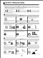
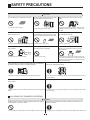
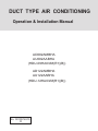
DUCT TYPE AIR CONDITIONING
Operation & Installation Manual
AD092AMBHA
AU092AABHA
(HDU-09HA03/M(R1)(B))
AD122AMBHA
AU122AABHA
(HDU-12HA03/M(R1)(B))
No. 0010572410
D
TABLE OF CONTENTS
2
CAUTIONS
3-5
SAFETY PRECAUTIONS
PARTS AND FUNCTIONS
6
MALFUNCTION
7-8
CARE AND MAINTENANCE
9-10
INSTALLATION MANUAL FOR OUTDOOR UNIT
11-14
INSTALLATION MANUAL FOR INDOOR UNIT
15-20
INSTALLATION MANUAL FOR ELECTRIC WIRING
21
INSTALLATION MANUAL FOR WIRE CONTROLLER
22
CHECK AND TEST RUN
23
1
CAUTIONS
Disposal of the old air conditioner
Before disposing an old air conditioner
that goes out of use, please make sure
it's inoperative and safe. Unplug the air
conditioner in order to avoid the risk of
child entrapment.
It must be noticed that air conditioner
system contains refrigerants, which
require specialized waste disposal. The
valuable materials contained in a air
conditioner can be recycled. Contact
your local waste disposal center for
proper disposal of an old air conditioner
and contact your local authority or your
dealer if you have any question. Please
ensure that the pipework of your air
conditioner does not get damaged prior
to being picked up by the relevant
waste disposal center, and contribute
to environmental awareness by
insisting on an appropriate, antipollution method of disposal.
Disposal of the packaging of your
new air conditioner
All the packaging materials employed
in the package of your new air
conditioner may be disposed without
any danger to the environment.
The cardboard box may be broken or
cut into smaller pieces and given to a
waste paper disposal service. The
wrapping bag made of polyethylene
and the polyethylene foam pads
contain no fluorochloric hydrocarbon.
All these valuable materials may be taken
to a waste collecting center and used
again after adequate recycling.
Consult your local authorities for the
nameand address of the waste materials
collecting centers and waste paper
disposal services nearest to your house.
Safety Instructions and Warnings
Before starting the air conditioner, read
the information given in the User's
Guide carefully. The User's Guide
contains very
important observations relating to the
assembly, operation and maintenance of
the air conditioner.
The manufacturer does not accept
responsibility for any damages that may
arise due to non-observation of the
following instruction.
Damaged air conditioners are not to
be put into operation. In case of doubt,
consult your supplier.
Use of the air conditioner is to be
carried out in strict compliance with the
relative instructions set forth in the User's
Guide.
Installation shall be done by professional
people, don't install unit by yourself.
For the purpose of safety, the air
conditioner must be properly grounded in
accordance with specifications.
Always remember to unplug the air
conditioner before opening inlet grill.
Never unplug your air conditioner by
pulling on the power cord. Always grip
plug firmly and pull straight out from the
outlet.
All electrical ropairs must be carried
out by qualified electricians. Inadequate
repairs may result in a major source of
danger for the user of the air conditoiner.
Do not damage any parts of the air
conditioner that carry refrigerant by
piercing or perforating the air
conditioner's tubes with sharp or pointed
items, crushing or twisting any tubes, or
scraping the coatings off the surfaces. If
the refrigerant spurts out and gets into
eyes, it may result in serious eye injuries.
Do not obstruct or cover the ventilation
grille of the air conditioner. Do not put
fingers or any other things into the
inlet/outlet and swing louver.
Do not allow children to play with the air
conditioner. In no case should children
be allowed to sit on the outdoor unit.
2
SAFETY PRECAUTIONS
Before starting to use the system, read carefully this"SAFETY PRECAUTIONS" to ensure a proper operation of the system.
Safety precautions described here are classified to " WARNING" and " CAUTION". Precautions which are shown in the column of
" WANING" means that an improper handing could lead to a grave result like a death, serious injury, etc. However, even if precautions
are shown in the column of " CAUTION", a very serious problem could occur depending on situation. Make sure to observe these safety
precautions faithfully because they are very important information to ensure the safety.
Symbols which appear frequently in the text have following meanings.
Strictly prohibited.
Observe instructions faithfully.
Provide a positive grounding.
When you have read through the manual, keep it always at hand for read consultation. If the operator is replaced, make sure to hand over
this manual to the new operator.
CAUTIONS FOR INSTALLATION
WARNING
The system should be applied to places as
office, restaurant, residence and the like.
The system should be installed by your
dealer or a professional installer.
Application to inferior environment such as an engineering shop, could cause equipment malfunction and
serious injury or death.
Installation by yourself is not encouraged because
it could cause such problems as water leakage,
electrical shock or fire accident by some improper
handing.
When you need some optional devices such as a humidifier, electric heater, etc., be sure to use the products
which are recommended by us. These devices should
be attached by a professional installer.
Installation by yourself is not encouraged because
it could cause such problems as water leakage,
electrical shock or fire accident by some improper
handing.
CAUTION
Depending on the place of installation, a
circuit breaker may be necessary.
Do not install nearby the place where may
have leakage of flammable gas.
Drain pipe should be arranged to provide a
positive draining.
ON
OFF
If the gas leakes and gathers around, it may cause
the fire.
Unless the circuit breaker is installed, it could If the pipe is arranged improperly, furniture or the
likes may be damaged by leaked water.
cause elecrical shocks.
Where strong winds may prevail, the
system should be fixed securely to prevent
a collapse.
Install on the place where can endure
the weight of air conditioner.
Bodily injury could result by a collapse.
Bodily injury could result by a careless installation.
CAUTIONS FOR OPERATION
Make sure the system is grounded.
Grounding cable should never be connected to a gas
pipe, city water pipe, lightning conductor rod or
grounding cable of telephone. If the grounding cable
is not set properly, it could cause electric shocks.
WARNING
You should refrain from exposing your body
directly to cool wind for a long time.
Do not poke the air inlet or outlet with a
bar, etc.
When any abnormal condition (scorching smell or others) is found, stop the operation immediately and turn
off the power switch. Then consult your dealer.
It could affect your physical condition or cause some
health problems.
Since the internal fan is operating with a high
speed, it could cause an injury.
If you continue the operation without removing the
cause, it could result in a trouble, electric shock or fire.
CAUTION
The system should never be used for any
other purposes than intended such as for
preservation of food, flora and fauna, precision deices or work of art.
It could cause deterioration of food or other problems.
Do not handle switches with a wet hand.
It could cause electric shocks.
3
Combustion apparatus should not be placed
allowing a direct exposure to wind of air conditioner.
Incomplete combustion could occur on the apparatus.
SAFETY PRECAUTIONS
CAUTION
Do not wash the air conditioner with water.
It could cause electric shocks.
Neither stand on the air conditioner nor
place something on it.
Do not install the system where the air outlet
reaches directly the flora and fauna.
Make sure to use a fuse of proper electric
rating.
It will not be good for their health.
Use of steel or copper wire in place of a fuse is strictly
prohibited because it could result in a trouble or fire
accident.
It is strictly prohibited to place a container of
combustible gas or liquid near the air conditioner or to spray it directly with the gas or liquid.
Do not operate the system while the
air outlet grill is removed.
There are risks of falling or injury by collapsed object. It could cause a fire accident.
Do not use the power switch to turn on or
off the system.
There is a risk of injury.
Do not touch the air outlet section while
the swing louver is operating.
Do not use such equipment as a water
heater, etc. around the indoor unit or the
wire controller.
There is a risk of injury.
If the system is operated at the vicinity of such equipment which generates steam, condensed water may
drip during cooling operation or it could cause a fault
current or short-circuit.
ON
OFF
It could cause a fire or water leakage.
When operating the system simultaneously with a combustion
apparatus, indoor air must be ventilated frequently.
Check occasionally the support structure of the unit for any damage
after a use of long period of time.
Insufficient ventilation could cause an oxygen deficiency accident.
If the structure is not repaired immediately, the unit could topple down to cause
a personal injury.
When cleaning the system, stop the operation and turn off the
power switch.
Do not put water containers on the unit such as a flower vase, etc.
Cleaning should never be done while the internal fans are running with high If the structure is not repaired immediately, the unit could topple down to cause
speed.
apersonal injury.
CAUTIONS FOR TRANSFER OR REPAIR
WARNING
Modification of the system is strictly prohibited. When the system
needs a repair, consult your dealer.
When the air conditioner is relocated, contact your dealer or a professional installer.
Improper practice of repair could cause water leakage, electric shock or fire. Improper practice of installation could cause water leakage, electric shock or fire.
4
SAFETY PRECAUTIONS
The machine is adaptive in following situation
1. Applicable ambient temperature range:
Indoor
Maximum:D.B / W.B 32 C/ 23 C
Minimum: D.B / W. 18 C/ 14 C
Outdoor
Maximum: D.B
Minimum: D.B
43 C/ 26 C
15 C
Indoor
Maximum: D.B
Minimum: D.B
27 C
20 C
Outdoor
Maximum: D.B / W.B 24 C/ 18 C
Minimum: D.B / W.B -7 C/ -8 C
Cooling
Heating
2. If the supply cord is damaged, it must be replaced by the manufacturer or its
service agent or a similar qualified person. An extend cord is not recommended,
the requirement of the power supply cord is H07RN-F 3G 2.5mm2 (suitable for
installation in European region)
3. If the fuse on PC board is broken please change it with the type of T3.15A /250VAC.
4. The waste battery shall be disposed properly.
5. The wiring method should be in line with the local wiring standard.
6. Use copper wire only. The connecting cable should be H05RN-F 4G 0.75mm2.
The power cable should be H07RN-F 3G 2.5mm2. All the cables shall have got the
European allthentication certificate.
7. The power supply connects from the outdoor side.
8. The breaker of the air conditioner should be all-pole switch; and the distance
between its two contacts should be no less 3mm.
9. The indoor unit installation height is at least 2.5m.
Note:
Part of the power supply of the air conditioner are not prepared because of the
requirement of the dealer, the power supply should be provided for oneself.
5
PARTS AND FUNCTIONS
Indoor Unit
Fan(inside)
Motor(inside)
Outdoor Unit
Air inlet
Connecting piping
and electrical wiring
Drain hose
Air outlet
6
MALFUNCTION
please check the following things about your air conditioner before making a servie call.
Unit fails to start
Is city supply power in
normal?
Is the power source
switch adjust cut in?
Isn't the signal receiving Isn't the earth leakage
section exposed to the breaker in action?
direct sunlight or strong
illumination?
It is dangerous. Turn off
the power supply switch
immediately and contact
the sales dealer.
ON
Power
stoppage?
OFF
Power supply switch is
not ON.
Cooling or heating is not sufficient
Isn't the air filter dirty?
Is the thermostat adjust
as required?
Isn't any doors or windows Doesn't any obstacle
exist at the air inlet or
left open?
outlet?
Cooling is not sufficient
Isn't the swing louver
horizontal?
Isn't sun-shine invading Isn't any unexpected
Isn't the room much
(At HEATING mode)
heating
load
generated?
direct?
crowded?
If swing louver is horizontal,
the blow wind does not reach
floor.
When the air conditioner does not operate properly after you have
checked the above mentioned items or when the following
phenomenon is observed, stop the operation of the air conditioner
Isn't it warming up?
and contact your sales dealer.
page 9
The fuse or breaker often shuts down.
Water drops off during cooling operation.
There is a irregularity in operation or abnormal sound is audible.
When the CHECK lamp flickers, an irregularity has occurred in the air conditioner.
The wind does not blow
during heating operation
Flickering
Content
of defect
Flickering
Content
of defect
F1
F2
F4
F5
F7
E1
The trouble of
The trouble
The trouble The trouble The trouble of The trouble of the wiring
of the
the
cooling
ice
of the room of the pipe
controller
the overload
module
over
and outdoor
temp.sensor temp. sensor heat
comumication
E4
E5
E6
E7
E8
E0
EA
E2
E3
No load
The trouble of
the indoor
and outdoor
comumication
EC
EE
The trouble The trouble of The trouble of The trouble of singlechip The trouble voltage too The trouble E2PROM
the outdoor bad
of the comp. the overload the outdoor
of the
bad
of the water high
room temp.
pipe temp.
too hot
current
overload
pump
sensor
sensor
cooliong
Note:
This unit has a function of automatic restart system after recovering power stoppage. Please contact
the sales dealer if it is not required.
7
MALFUNCTION
The followings are not malfunction
Water flowing
sound is heard.
Sh
Sh uru
ur
u
When the air conditioner is started, when the compressor starts or
stops during operation or when the air conditioner is stopped, it
sometimes sounds "shuru shuru" or "gobo gobo". It is the flowing
sound of the refrigerant, and it is not a trouble.
Cracking sound is heard.
This is caused by heat expansion or contraction of plastics.
It smells.
Air which blows out from the indoor unit sometimes smells.
The smell results from residents of tobacco smoke or cosmetics
stuck inside of unit.
During operation,
white fog comes
out of indoor unit.
When the air conditioner is used at restaurant etc. where dense
edible oil fume is always exists, white fog sometimes blows out
of air outlet during operation.
In this case consult sales dealer for cleaning the heat exchanger.
It is switched into the FAN mode
during cooling.
The air conditioner can not be
restarted soon after it stops.
Unit does
not start
Air does not blow or the fan
speed can not be changed during
dehumidifying
To prevent frost from being accumulated on the indoor unit heat
exchanger, it is sometimes automatically switched to the FAN mode
but it will soon return to the cooling mode.
Even if the operation switch is turned on, cooling, dehumidifying
or heating is not operable for three minutes after the conditioner is
stopped. Because the protecting circuit is activated.
Wait for
(During this time air conditioner operates in fan
three
minutes
mode.)
When it is excessively cooled during dehumidifying, the blower
automatically repeats reducing and lowering the fan speed.
During operation, operation mode Isn't the AUTO mode selected?
In the case of AUTO mode, operation mode is changed automatihas changed over automatically.
cally from cooling to heating or vise-versa according to the room
temperature.
Water or steam generates from
the outdoor unit during heating.
This results when frost accumulated on the outdoor unit is removed
(during defrosting operation).
8
CARE AND MAINTENANCE
Points to observe
Turn off the power supply switch.
Do not touch with wet hand.
Do not use hot water or volatileliquid.
ON
Thinner
Do not
use!
Benzine
Tooth powder
OFF
CAUTION
Do not open the inlet grill until fan stops completely.
Fan will continue rotating for a while by the law of inertia after operation is being stopped.
Cleaning
1. Clean the air filter by lightly tapping it or with the cleaner. It is more
effective to clean the air filter with water.
If the air filter is very dirty, dissolve neutral detergent in the lukewarm
water (approx. 30*), rinse the air filter in the water, and thoroughly
wash the air filter off the detergent in the plain water.
2. After drying the air filter, set it up on the air conditioner.
CAUTION
Do not dry the air filter with fire.
Do not run the air conditioner without the air filter.
Care and Cleaning of the unit
Clean with soft and dry cloth.
If it is very dirty, dissolve neutral detergent in the lukewarm water and make the cloth wet with the water.
After wiping, clean off the detergent using clean water.
Post-Season Care
Operate the unit with FAN mode on a fair day for about half a day to dry the inside of the unit well.
Stop operation and turn off the power supply switch. Electric power is consumed even the air conditioner is in stop.
Clean the air filter and set it in the place.
Pre-Season Care
See that there are no obstacles blocking the air inlet and air outlet of both indoor and outdoor units.
Make sure that the air filter is not dirty.
Cut in the power supply switch 12 hours before starting run.
9
CARE AND MAINTENANCE
"HOT KEEP"is operated in the following cases.
When heating is started:
In order to prevent blowing out of cool wind, the indoor unit fan stopped
according to the room temperature which heating operation is started. Wait
for approx. 2 to 3 minute, and the operation will be automatically changed
to the ordinary heating mode.
Defrosting operation (in the heating mode):
When it is liable to frost. the heating operation is stopped automatically
for 5 to 12 minutes once per approx. one hour, and defrosting is operated.
After defrosting is completed, operation mode is automatically changed
to ordinary heating operation.
When the room thermostat is actuated:
When room temperature increases and room temperature controller actuates, the fan speed is automatically changed to stop under low temperature
condition of indoor heat exchanger. When room temperature decreases,
air conditioner automatically changes over to ordinary heating operation.
WARMING OPERATION
Heat pump type warming
With the heat pump type warming, the mechanism of heat pump that concentrate heat of
outdoor air with the help of refrigerant to warm the indoor space, is utilized.
Defrosting operation
When a room is warmed with a heat pump type air conditioner, frost accumulates on the
heat exchanger of outdoor unit along with the drop of indoor temperature. Since the
accumulated frost reduces the effect of warming, it is necessery to automatically switch
the operation to the defrosting mode. During the defrosting operation, heating operation
is interrupted.
Atmospheric temperature and warming capacity
Warming capacity of heat pump type air conditioner decreases along with the
drop of outdoor temperature.
When the warming capacity is not sufficient, it is
recommended to use another heating implement.
Period of warm-up
Since the heat pump type air conditioner employs a method
to circulate warm winds to warm the entire space of a room,
it takes time before the room temperature rises.
It is recommendable to start the operation a little earlier in a very cold morning.
10
INSTALLATION MANUAL FOR OUTDOOR UNIT
Confirm the following items for safe and comfortable use of air conditioner.
The installation work is to be burden on the sales dealer, and do not conduct it by yourself.
Installation place
Avoid installing the air conditioner Install the unit at well ventilated
near the place where possibility of place.
inflammable gas leakage exists.
Install the air conditioner firmly on
the foundation that can fully support
the weight of the unit.
If some obstacle exist, it may cause
capacity reduction or noise increase.
If not, it may cause vibration or noise.
Explosion (Ignition) may occur.
Select the place so as not to annoy
neighbor with the hot air or noise.
Snow protection work is necessary
where outdoor unit is blocked up
by snow.
For details consult your sales dealer.
It is advisable not to install the air conditioner at the following special place.
It may cause malfunction, consult the
sales dealer when you have to install
the unit on such a place.
The place where corrosive gas generates
(Hot spring area etc.)
The place where salt breeze blows
(Seaside etc.)
The place where dense soot smoke exists
The place where humidity is extraordinarily high
The place where near the machine which
radiates the electromagnetic wave
The place where voltage variation is considerably large
Electric work
The electric work must be burden on the authorized engineer with qualification for electric work and
grounding work, and the work must be conducted in accordance with electric equipment technical standard.
The power source for the unit is to be of exclusive use.
An earth leakage breaker should be installed.(This is necessary to prevent electric shock.)
The unit must be grounded.
When you change your address or the installation place
Special technology is required for removal or reinstallation of air conditioner, consult the sales dealer.
Besides, construction expense is charged for removal or reinstallation.
For inspection and maintenance
The capacity of air conditioner will decrease by contamination of inside of unit when it is used for about
three years although depending upon the circumstances under which it is used, and so in addition to the
usual maintenance service, special inspection/maintenance service is necessary. It is recommended to
make a maintenance contract (charged) by consulting your sales dealer.
11
INSTALLATION MANUAL FOR OUTDOOR UNIT
<Heat Pump model/Cooling Only model >
WARNING
BE SURE TO READ THESE INSTRUCTIONS CAREFULLY BEFORE BEGINNING INSTALLATION.
FAILURE TO FOLLOW THESE INSTRUCTIONS COULD CAUSE SERIOUS INJURY OR DEATH,
EQUIPMENT MALFUNCTION AND/OR PROPERTY DAMAGE. BE SURE TO READ INSTALLATION
MANUAL FOR INDOOR UNIT WITH THIS MANUAL.
1. Accessories
Edging
"Edging" for protection of electric wires from an
opening edge.
2. Selection of the place of installation
Select the place of installation satisfying the following conditions and, at the same time, obtain
a consent from the client or user.
Place where air circulates.
Place free from heat radiation from other heat sources.
Place where drain water may be discharged.
Place where noise and hot air may not disturb the neighborhood.
Place where there is not heavy snowfall in the winter time.
Place where obstacles do not exist near the air inlet and air outlet .
Place where the air outlet may not be exposed to a strong wind.
Place surrounded at four sides are not suitable for installation. A 1m or more of overhead
space is needed for the unit.
Mount guide-louvers to place where short-circuit is a possibility.
When installing several units, secure sufficient suction space to avoid short circuiting.
(1) Open space requirement around the unit
Unit: mm
Air inlet
L3
L2
500
(Servicing
space)
Air
inlet
Air outlet
Distance
L1
Case
I
II
III
open
open
500
L2
300
0
open
L3
150
300
150
L1
(2) Installation where the area with strong winds.
Install the unit so that the air outlet section of the unit must NOT be
faced toward wind direction.
NO
3. Installation of outdoor unit
(1) Installation
Wind direction
Fix the unit in a proper way according to the condition of a place where it is installed by referring to the following .
(a) Concrete foundation
Foundation anchor
Unit
Unit
Anchor bolt
Concrete foundation
Concrete foundation
To fix by bolts
Anchor bolt
Note (1) Give enough room for the concrete
foundation to fix by anchor bolts.
Note (1) Place the concrete foundation deep enough.
Install the unit so that the angle of inclination must be less than 3 degrees.
12
INSTALLATION MANUAL FOR OUTDOOR UNIT
4. Refrigerant piping
(1) Outline piping
Flare connection
3-way valve
Liquid
pipe
Outdoor
Indoor
unit
unit
3-way valve
Gas pipe
Flare connection
Gas piping
12.7(1/2")x1.0mm
Liquid piping
6.35(1/4")x0.8mm
Install the removed flared nuts to the pipes to be connected,
then flare the pipes.
90 + 0.5
(2) Piping size
(3) Limitations for one way piping length and vertical height
One way piping length: less than
15m.
Precautions for refrigerant piping
Do not twist or crush piping.
Be sure that no dust is mixed in piping.
Bend piping with as wide angle as possible.
Keep insulating both gas and liquid piping.
Check flare-connected area for gas leakage.
(4) Piping connection
Connecting method
Apply refrigerant oil at half union and flare nut.
To bend a pipe, give the roundness as large as possible not to crash the pipe.
When connecting pipe, hold the pipe centre to centre then screw nut on by hand, refer
to Fig.
Be careful not to let foreign matters, such as sands enter the pipe.
Pipe dia
Forced fastening without centering may
damage the threads and cause a gas
leakage.
Liquid pipe 6.35mm(1/4")
Gas pipe 12.7mm(1/2")
13
Fastening torque
11.8N.m
49.0N.m
INSTALLATION MANUAL FOR OUTDOOR UNIT
(5) Purging method ( the refrigerant is R407C)
Liquid pipe
6.35mm(1/4'')
To use vacuum pump
Gas pipe
1
12.7mm(1/2'')
Detach the service port's cap of 3-way valve, the
3-way valve
3-way valve
valve rod's cap for 3-way valve and 3-way's, connect
the service port into the projection of charge hose
Gaugemanifold
(low) for gaugemanifold. Then connect the projection
of charge hose (center) for gaugemanifold into
vacuum pump.
Vacuum pump
2
Open the handle at low in gaugemanifold, operate
vacuum pump. If the scale-moves of gause (low)
2 Open
reach vacuum condition in a moment, check 1 again.
3
Vacuumize for over 15min. And check the level gauge
which should read -0.1 MPa (-76 cm Hg) at low
pressure side. After the completion of vacuumizing,
close the handle 'Lo' in gaugemanifold and stop the
3 Close
operation of the vacuum pump.
Check the condition of the scale and hold it for 1-2min.
If the scale-moves back in spite of tightening, make
flaring work again, the return to the beginning of 3 .
3-way valve
4
3-way valve
Open the valve rod for the 3-way valve to and angle of
anticlockwise 90 degree.
90
90
After 6 seconds later, close the 3-way valve and male
the inspection of gas leakage.
5
No gas leakage?
In case of gas leakage, tighten
parts of pipe connection. If
leakage stops, then proceed 6
steps.
Service port
4 90 for 6 sec.
If it does not stop gas leakage, discharge
whole refrigerants from the serice port.
After flaring work again and vacuumize,
fill up prescribed refrigerant from the gas
cylinder.
6
Detach the charge hose from the service port, open
3-way valve and 3-way. Turn the valve rod
anticlockwise until hitting lightly.
3-way valve
3-way valve
7
To prevent the gas leakage, turn the service port's
6
cap, the valve rod'd cap for 3-way valve and 3-way's
6
a lottle more than the point where the torque increases
suddenly.
8
After attaching the each caps, check the gas leakage
around the caps.
3-way valve
3-way valve
CAUTION:
If the refrigerant of the air conditioner leaks, it is necessary to make
7 Valve rod cap
all the refrigerant out, then charge the liquid refrigerant into air
conditioner according to the amount marked on the name plate.
7 Valve rod cap
14
7 Service port cap
INSTALLATION MANUAL FOR INDOOR UNIT
1. Safety precautions
Please read these "Safety Precautions" first then accurately execute the installation work.
Though the precautionary points indicated herein are divided under two headings,
WARNING
and
CAUTION , those points which are related to the strong possibility of an installation done in
error resulting in death or serious injury are listed in the
WARNING section. However, there is
also a possibility of serious consequences in relationship to the points listed in the
CAUTION
section as well. In either case, important safety related information is indicated, so by all means,
properly observe all that is mentioned.
After completing the installation, along with confirming that no abnormalities were seen from the
operation tests, please explain operating methods as well as maintenance methods to the user
(customer) of this equipment, based on the owner's manual.
Moreover, ask the customer to keep this sheet together with the owner's manual.
WARNING
This system should be applied to places as office, restaurant, residence and the like. Application to inferior
environment such as engineering shop could cause equipment malfunction.
Please entrust installation to either the company which sold you the equipment or to a professional contractor.
Defects from improper installations can be the cause of water leakage, electric shocks and fires.
Execute the installation accurately, based on following the installation manual. Again, improper installations can
result in water leakage, electric shocks and fires.
When a large air-conditioning system is installed to a small room, it is necessary to have a prior planned
countermeasure for the rare case of a refrigerant leakage, to prevent the exceeding of threshold concentration.
In regards to preparing this countermeasure, consult with the company from which you perchased the equipment,
and make the installation accordingly. In the rare event that a refrigerant leakage and exceeding of threshold
concentration does occur, there is the danger of a resultant oxygen deficiency accident.
For installation, confirm that the installation site can sufficiently support heavy weight. When strength is insufficient,
injury can result from a falling of the unit.
Execute the prescribed installation construction to prepare for earthquakes and the strong winds of typhoons
and hurricanes, etc. Improper installations can result in accidents due to a violent falling over of the unit.
For electrical work, please see that a licensed electrician executes the work while following the safety standards
related to electrical equipment, and local regulations as well as the installation instructions, and that only exclusive
use circuits are used.
Insufficient power source circuit capacity and defective installation execution can be the cause of electric shocks
and fires.
Accurately connect wiring using the proper cable, and insure that the external force of the cable is not conducted
to the terminal connection part, through properly securing it. Improper connection or securing can result in heat
generation or fire.
Take care that wiring does not rise upward, and accurately install the lid/service panel. Its improper installation
can also result in heat generation or fire.
When setting up or moving the location of the air conditioner, do not mix air etc. or anything other than the
designated refrigerant (R407C) within the refrigeration cycle.
Rupture and injury caused by abnormal high pressure can result from such mixing.
Always use accessory parts and authorized parts for installation construction. Using parts not authorized by this
company can result in water leakage, electric shock, fire and refrigerant leakage.
CAUTION
Execute proper grounding. Do not connect the ground wire to a gas pipe, water pipe, lightning rod or a telephone
ground wire. Improper placement of ground wires can result in electric shock.
The installation of an earth leakage breaker is necessary depending on the established location of the unit. Not
installing an earth leakage breaker may result in electric shock.
Do not install the unit where there is a concern about leakage of combustible gas.
The rare event of leaked gas collecting around the unit could result in an outbreak of fire.
For the drain pipe, follow the installation manual to insure that it allows proper drainage and thermally insulate
it to prevent condensation. Inadequate plumbing can result in water leakage and water damage to interior items.
15
INSTALLATION MANUAL FOR INDOOR UNIT
NOTICE
All Wiring of this installation must comply with NATIONAL, STATE AND LOCAL REGULATIONS.
These instructions do not cover all variations for every kind of installation circumstance. Should further
information be desired or should particular problems occur, the matter should be referred to your local
distributor.
WARNING
BE SURE TO READ THESE INSTRUCTIONS CAREFULLY BEFORE BEGINNING INSTALLATION. FAILURE TO FOLLOW THESE INSTRUCTIONS COULD CAUSE SERIOUS INJURY OR DEATH, EQUIPMENT
MALFUNCTION AND/OR PROPERTY DAMAGE.
(1) Preparation of indoor unit
Before or during the installation of the unit, assemble necessary optional panel etc. depending
on the specific type.
(2) Select places for installation satisfying following conditions and at the same time obtain
the consent on the part of your client user.
(a) Places where chilled or heated air circulates freely.
When the installation height exceeds 3m warmed air stays close to the ceiling. In such
cases, suggest your client users to install air circulators.
(b) Places where perfect drainage can be prepared and sufficient drainage.
(c) Places free from air disturbances to the suction port and blowout hole of the indoor unit,
places where the fire alarm may not malfunction or short-circuit.
(d) Places with the environmental dew-point temperature is lower than 28 C and the relative
humidity is less than 80%.
(When installing at a place under a high humidity environment, pay sufficient attention to
the prevention of dewing such as thermal insulation of the unit. )
(e) Ceiling height shall have the following height.
Installation space
Combination with
silent panel
1000 or more
100 or
more
366mm
100 or
more
Obstacle
50 or more
Unit: mm
(3) Avoid installation and use at those places listed below.
(a) Places exposed to oil splashes or steam (e.g. kitchens and machine plants).
Installation and use at such places incur deteriorations in the performance or corrosion
with the heat exchanger or damage in molded synthetic resin parts.
(b) Places where corrosive gas (such as sulfurous acid gas) or inflammable gas (thinner,
gasoline, etc) in generated or remains. Installation and use at such places cause corrosion
in the heat exchanger and damage in molded synthetic resin parts.
(c) Places adjacent to equipment generating electromagnetic waves or high-frequency waves
such as in hospitals.
Generated noise may cause malfunctioning of the controller.
16
INSTALLATION MANUAL FOR INDOOR UNIT
(4) Preparation for suspending the unit
(a) Figure of installation dimension: (unit: mm)
450
830
225
220
80
125
no
be thin
d
l
i
ou w
sh s
re cle
e
Th bsta
o 0
25
When install the duct hidden type indoor unit, the return air box must be
designed and installed, as Figure3, Figure4.
The distance between the air outlet of duct and the air outlet of air conditioner
should be no more than 0.5m.
This duct type air conditioner is low static pressure model.
(Figure 3)
Building roof of installation
*0.5m
A
Ceiling
Air out duct Unit
Return air box
Return air
Air supply
(Figure 4)
Air outlet grille
Air supply
There should be
no obstacles
within 1m
Unit
Return air box
Return air
17
INSTALLATION MANUAL FOR INDOOR UNIT
A amplified
M8 wide expansion screw bolt
M8 hoisting screw
Unit
M8 wide lock washer
M8 screw nut
28
B Rivet
(Figure 6)
C
Air supply passage
B
B amplified
(Figure 5)
C amplified
B
Top panel of unit
Use screw to
fix top panel
Air supply
passage Air outlet grille
Install the hoisting screw*
Use M8 or M10 hoisting screw (4, prepare on site) (When the height of hoisting
screw is more than 0.9m, you must use M10), their gaps refer to the dimension of
air conditioner, according to the original structure and the following method to install.
Wood structure
Put up the frame wood on the beam and mount the hoisting screws.
Frame wood
Beam
Hoisting screw
New cement panel
Use embedded parts and foot screw, etc to mount.
(Knife type
embedded part)
(Louver type
embedded part)
18
Iron
Foot screw
(hoisting foot screw for
connection pipe)
INSTALLATION MANUAL FOR INDOOR UNIT
Original cement panel
Use the in hole hinge, in hole plug or in hole screw.
Steel structure
Suspending bolt
Directly use angle steel or new
angle steel for support.
Hoisting screw
Suspending of indoor unit
Angle steel for support
Fix the cap of hoisting screw on and suspend them on the T groove of the hoisting
part of the unit.
Use gradienter to keep the level degree of the unit within 5mm.
* Notice
In order to normally drain water, the drain hose should be mated according to the
installation manual. In order to avoid dew-forming, thermal insulation treatment
should be done.
Improper connection pipe may cause water enter indoor.
Requirements:
The indoor side drain hose should be thermal insulated.
The parts connected with indoor unit should be thermal insulated. Improper thermal
insulation may cause dew-forming phenomenon.
The drain hose should be downwards slant (over 1/100) and there should be no
S-shaped bend. Otherwise, abnormal sound may occur.
The horizontal length of the drain hose should be less than 20m. If the connection
pipe is too long, the supporting frame should be set every 1.5~2m to prevent pipe
from rise and fall.
For the centralized connection pipe, please perform work as the following Figure
shown.
Pay attention not to exerting external force to the connection part of the drain hose.
1m*1.5m
Supporting frame
S-shaped bend
Downward slant over 1/100
Thermal insulation material (user self-provided)
As large as possible
(about 10cm)
Wall
Outside
Slant
VP30
Downward slant over 1/100
Drain hose
(user self-provided)
19
INSTALLATION MANUAL FOR INDOOR UNIT
Material of connection pipe and thermal insulation
Material of connection pipe
Stiff PVC pipe VP 20mm (inside diameter)
Foam polyethylene pipe, thickness over 10mm
Material of thermal insulation
Confirm drainage
Perform test run to insure the condition of drainage, the connection part
of the connection should not leak water. The confirmation must be
performed even if install in winter.
!
Warning
During installation, if refrigerant leakage occurs, please immediately take
ventilation measure. If the refrigerant gas meet the fire, it may generate poisonous
gas.
After finishing installation work, please make sure there is no refrigerant leakage.
If the leaked refrigerant gas meet heater and oven, etc. fire sources, it may
generate poisonous.
Material and dimension of connection pipe
Depenbing on the outdoor unit.For details,please refer to the operation manual
attached with outdoor unit.
The permitted length and fall of connection pipe
Material of
connection pipe
Dimension of
connection pipe
Phosphorus oxidized copper seamless pipe
(TP2) for air conditioner
12.7
Gas side
Liquid side
6.35
Connection of refrigerant pipe
Perform with two spanners
When performing the connection work of flare nut,
connect all the refrigerant pipe.
When connecting the connection pipe of indoor
unit, must use two spanners to perform.
For the installation torque, please refer the
following Table.
External diameter of Installation torque (N.m) Add to installation torque (N.m)
connection pipe (mm)
6.35
11.8(1.2kgf.m)
13.7(1.4kgf.m)
12.7
49.0(5.0kgf.m)
53.9(5.5kgf.m)
20
INSTALLATION MANUAL FOR ELECTRIC WIRING
5. Electric wiring
Cautions: Use copper wire only.Parameters of connecting
line : H05RN-F 4G0.75mm2
Power supply :1PH,220-230V~,50Hz, connect from outside.
1(L
)
Wiring methods:
1.Wiring method of ring terminal
For connecting line which end is a ring,its wiring method
as shown in the right figure: remove wiring screw and pass
it through the end ring of connecting line,then connect it to
the terminal block and tighten screw.
2. Wiring method of straight terminal
Wiring method of ring terminal
Incorrect crimp
connection of wire
Correct crimp
connection of wire
For connecting line which end is not a ring, its wiring method
as follows: loosen wiring screw ans insert the end of connecting
line totally into the terminal block,then tighten the screw and pull
the connecting line slightly to confirm that it is clamped firmly.
Terminal block
Crimp connection
clamp
Crimp connection method of connecting line
After finishing wiring.connecting line must be fastened by
wire clamp,which pressed on the external sheath of the
connecting line, as shown in the right figure:
Wiring of indoor unit
Open air inlet grill
Take the leading end of connecting line
Connect connecting line according to wiring methods
and wiring diagram of indoor and outdoor unit
Fasten connecting line according to crimp connection
method of connecting line.
Reinstall air inlet grill.
1
2
3
1
2
3
Indoor unit
terminal block
Outdoor unit
terminal block
to power supply
1.Installation fixing
Fix outdoor unit installation bracket on the wall using a
M10 anchor bolt.Fix outdoor unit on the installation bracket
firmly using bot(M10) and nut, and keep it on horizontal level.
When installing on the wall or on the roof ,fix the bracket,
firmly to prevent earthquake or storm.
Be sure to use rubber-damping cushion to reduce unit vibration.
2.Installation of drain elbow
Installation of drain elbow.(Only for heat pump type air conditioner,
no drain elbow for single cooling type).If use drain elbow,please
install as shown in the figure.
Do not use drain elbow in cold place (temperature successively
below 0 C)
Terminal
Wire clamp
Power supply
Connecting wire
between inner and outer
3. Connection of outdoor piping
Connect the connecting pipe according to the piping connection
method
4.Wiring connection
1.Open the wiring cover and loosen the wiring clamp.
2.Lead the connecting wire out and pass it through the wiring clamp.
3.Connect the connecting wire according to the wiring method and
diagram
4. Confirm the ends of wire are connected well, safe and correct.
5. After finishing wiring, press the connecting wire according to the
wire crimp connection method and reinstall the cover.
21
1
2
3
INSTALLATION MANUAL FOR WIRE CONTROLLER
Upper cover of
wire controller
1.Remove the upper cover of wire controller
The PC board is installed on the back cover of
wire controller. When remove the upper cover,
pay attention not to damage PC board.
HEALTH
C
F
SET
RECOVERY
CHECK
Back cover of
wire controller
2.Install wire controller
**Drill 2 wall holes according to the position of the 2 screw holes on the back
*cover of wire controller, then hit wood in the wall holes. Put the 2 screw holes
*on the back cover of wire controller properly to its corresponding wood, then
*use wood screws to fix the back cover on the wall.
Note:
Install the back cover of wire controller on the even wall as possible as can.
When tightening the wood screw, do not use to tight force, otherwise the wire
controller may be damaged.
Note:
When connecting wire, please keep a
certain distance between signal wire and
electric wire. (over 10mm)
Dimension of signal wire:
Type of wire
Dimension
Shield wire (4 cords)
0.33mm
2
3.Indoor unit wire connection
Connect the terminals (A, B, C, D,) on the wire
controller to the terminals on the indoor PC
panel (A, B, C, D,) respectively.
Arrange wire from this part
AB
CD
HEALTH
C
F
SET
CHECK
RECOVERY
Back cover
wire controller
HEALTH
C
F
SET
CHECK
RECOVERY
The connection between indoor unit
and wire controller and indoor unit
and outdoor unit should use shield
wire. And the two ends of the shield
wire should be grounded,
otherwise, the disturbance will
cause unit abnormal operation.
Upper cover
Shield wire
of wire
controller
Grounded
Grounded
Note:
Confirm the connection part of terminals is firm and will not touch shield wire.
4. Cover the wire controller upper cover
Pay attention not to press the connection wire.
Note: Do not touch PC board by hand.
22
CHECK AND TEST RUN
Other instruction
1.Set of the air sending of the fan motor
Before leaving factory, the rotation speed of fan motor has already been set at
standard choice. When the indoor unit uses free air sending and not needing to
connect with duct, the fan speed of indoor unit is set at standard choice. When
the indoor unit needs to connect with duct, please according to the following figure
shown to change the connection of the connector installed on the side of electric
box.
Standard air sending
High fan speed air sending
*Before leaving factory*
One side of the control box One side of the control box
Connector (White)
Connector (White)
(Red)
(White)
One side of Fan motor
One side of Fan motor
The relative relation between fan speed and static pressure
2. Cut and flaring method
Use pipe cutter to cut the pipe, the burrs must be removed.
Unit: Pa
Standard fan speed
0
High fan speed
After inserting the flarer, perform flared nut.
30
Flaring
dimensions
as
follows:
Flarer
A
Connent pipe Pipe diameter Dimension A (mm)
Liquid pipe 6.35mm (1/4î)
0.8-1.5
Gas pipe 12.7mm (1/2î)
1.0-0.2
Incorr
Correct
Slant
Broken
Burrs
Uncompleted Too long
3.Configuration of power supply
Air conditioner must use special power supply system (above 20A), and qualified electrician makes
wiring and fixing according to wiring regulations specified in national standard.
In socket, exactly distinguish earth wire with neutral wire and it is wrong to connect them together.
A leakage breaker must be installed.
Parameters of power supply: H07RN-F 3G 2.0mm2
Connection method is Y-connection .If the power cord is damaged, it must be replaced by
professional people of manufacturer or its maintenance department or similar to avoid dangers.
4.Installation check and test run
Require customers to use air conditioner according to the operation manual.
The items checked during test run,please mark
in
Is the wiring of indoor and outdoor unit secured firmly?
How about the thermal insulation of the pipe joint:
Is the electrical wiring between indoor and outdoor unit
connected to the terminal block firmly?
Is the display on the control board (LCD) correct?
Cooling normal?
No gas leakage on the pipe joint ?
Is the drainage hose arranged correct?
Is the earthing wire connected firmly?
Any noise?
For the power supply
1 shall be connected to the live wire.
Does the indoor temperature regulator work normally?
2 shall be connected to the neutral wire.
Is the power supply voltage conformed to the
electrical regulation?
Shall be connected to the earth wire.
23