1
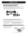
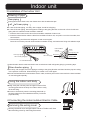
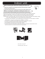
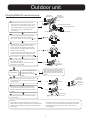
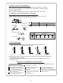
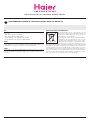
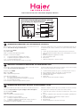
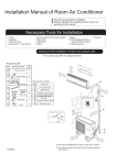
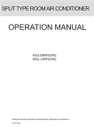
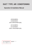
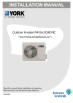
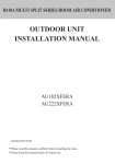
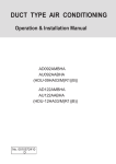
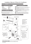
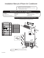
Installation Manual of Room Air Conditioner
Read this manual before installation
Explain sufficiently the operating means to the user
according to this manual.
Necessary Tools for Installation
1.Driver
2.Hacksaw
3.Hole core drill
4.Spanner(17,19 and 26mm)
5.Torque wrench(17mm,22mm,26mm)
6.Pipe cutter
7.Flaring tool
8.Knife
9.Nipper
10.Gas leakage detector or
soap-and-water solution
11.Measuring tape
12.Reamer
Drawing for the installation of indoor and outdoor units
The models adopt HFC free refrigerant R410A
No.
1
Accessory parts
Remote controller
2
R-03 dry battery
Number
of
articles
1
2
1
3
Mounting plate
4
4X25
Screw
5
6
Plastic cap
Drain-elbow
Pipe supporting plate
4
more than 5cm
Accessory parts
Optional parts for piping
Mark
Parts name
A
Non-adhesive tape
B
Adhesive tape
mo
re th
C
Saddle(L.S) with screws
D
E
Connecting electric cable
for indoor and outdoor
Drain hose
F
Heating insulating material
G
an
10c
m
mo
re th
Piping hole cover
an
10c
m
Attention must be paid to
the rising up of drain hose
1
A
1
Arrangement of piping directions
Rear left
Rear
right
Left
Below
C
Right
more
mo
re
tha
n1
than
10cm
0c
m
D
more
an
re th
mo
60cm
The marks from A to G in the figure are the parts numbers.
The distance between the indoor unit and the floor should be
more than 2m.
No.001051
than
15c
m
280
140
415
140
Floor fixing dimensions
of the outdoor unit
(Unit:mm)
Fixing of outdoor unit
Fix the unit to concrete or block with bolts( 10mm) and nuts firmly and horizontally.
When fitting the unit to wall surface, roof or rooftop, fix a supporter surely with nails
or wires in consideration of earthquake and strong wind.
If vibration may affect the house, fix the unit by attaching a vibration-proof mat.
Indoor Unit
Selection of Installation Place
Place, robust not causing vibration, where the body can be supported
sufficiently.
Place, not affected by heat or steam generated in the vicinity, where
inlet and outlet of the unit are not disturbed.
Place, possible to drain easily, where piping can be connected with the
outdoor unit.
Place, where cold air can be spread in a room entirely.
Place, nearby a power receptacle, with enough space around. (Refer
to drawings).
Place where the distance of more than lm from televisions, radios,
wireless apparatuses and fluorescent lamps can be left.
In the case of fixing the remote controller on a wall, place where the
indoor unit can receive signals when the fluorescent lamps in the room
are lightened.
Outdoor Unit
Place, which is less affected by rain or direct sunlight and is
sufficiently ventilated.
Place, possible to bear the unit, where vibration and noise are
not increased.
Place, where discharged wind and noise do not cause a
nuisance to the neighbors.
Place, where a distance marked
is available as illustrated
in the above figure.
Power Source
Before inserting power plug into receptacle, check the voltage without fail. The power source is the same as the corresponding name plate.
Install an exclusive branch circuit of the power.
A receptacle shall be set up in a distance where the power cable can be reached. Do not extend the cable by cutting it.
Selection of pipe
To this unit, both liquid and gas pipes shall be insulated
as they become low temperature in operation.
Use optional parts for piping set or pipes covered with
equivalent insulation material.
The thickness of the pipe must be 0.8mm at least.
2
Liquid pipe
6.35mm(1/4")
Gas pipe
9.52mm(3/8")
Indoor unit
1.Fitting of the Mounting Plate and Positioning of the wall Hole
When the mounting plate is first fixed
1.Carry out, based on the neighboring pillars or lintels, a proper leveling for the plate to be
fixed against the wall, then temporarily fasten the plate with one steel nail.
2. Make sure once more the proper level of the plate, by hanging a thread with a weight from
the central top of the plate, then fasten securely the plate with the attachment steel nail.
3. Find the wall hole location A using a measuring tape
A=145mm
30mm
B= 60mm
When the mounting plate is fixed side bar and lintel
Fix to side bar and lintel a mounting bar, Which is separately sold, and then fasten
the plate to the fixed mounting bar.
Refer to the previous article, "
position of wall hole.
When the mounting plate is first fixed ", for the
2.Making a Hole on the Wall and Fitting the Piping Hole Cover
Make a hole of 60 mm in diameter,
slightly descending to outside the wall.
Install piping hole cover and seal it
off with putty after installation
Indoor side
Wall hole
60mm
(Section of wall hole)
3
Outdoor side
Thickness
of wall
Piping hole pipe
Indoor unit
3.Installation of the Indoor Unit
Drawing of pipe
Rear piping
Draw pipes and the drain hose, then fasten them with the adhesive tape
Left Left-rear piping
In case of left side piping, cut away, with a nipper, the lid for left piping.
In case of left-rear piping, bend the pipes according to the piping direction to the mark of hole for left-rear
piping which is marked on heat insulation materials.
1. Insert the drain hose into the dent of heat insulation materials of indoor unit.
2. Insert the indoor/outdoor electric cable from backside of indoor unit, and pull it out on the front side, then
connect them.
3. Coat the flaring seal face with refrigerant oil and connect pipes.
Cover the connection part with heat insulation materials closely, and make sure fixing with adhesive tape
Heat insulation
material
Piping
Pipe supporting plate
Lid for right piping
Lid for left piping Drain hose
Lid for under piping pipe
Indoor/outdoor
electric cable
Fix with adhesive tape
Indoor/outdoor electric cable and drain hose must be bound with refrigerant piping by protecting tape.
Other direction piping
Cut away, with a nipper, the lid for piping according to the piping direction and then bend the pipe according
to the position of wall hole. When bending, be careful not to crash pipes.
Connect beforehand the indoor/outdoor electric cable, and then pull out the connected to the heat insulation
of connecting part specially.
Fixing the indoor unit body
Hang surely the unit body onto the upper notches of the
mounting plate. Move the body from side to side to verify
its secure fixing.
In order to fix the body onto the mounting plate,hold up
the body aslant from the underside and then put it down
perpendicularly.
4.Connecting the indoor/outdoor Electric Cable
Removing the wiring cover
Remove terminal cover at right bottom corner of indoor unit, then
take off wiring cover by removing its screws.
4
Indoor unit
When connecting the cable after installing the indoor unit
1. Insert from outside the room cable into left side of the wall hole, in which
the pipe has already existed.
2. Pull out the cable on the front side, and connect the cable making a loop.
When connecting the cable before installing the indoor unit
Insert the cable from the back side of the unit, then pull it out on the front side.
Loosen the screws and insert the cable ends fully into terminal block, then tighten the screws.
Pull the cable slightly to make sure the cables have been properly inserted and tightened.
After the cable connection, never fail to fasten the connected cable with the wiring cover.
Note: When connecting the cable, confirm the terminal number of indoor and outdoor units carefully. If wiring
is not correct, proper operation can not be carried out and will cause defect.
1. If the supply cord is damaged, it must be replaced by the manufacturer or its service agent or a similar
qualified person. The type of connecting wire is H05RN-F or H07RN-F.
2. If the fuse on PC board is broken please change it with the type of T. 3.15A/250V.
3. The wiring method should be in line with the local wiring standard.
4. After installation, the power plug should be easily reached.
5. A breaker should be incorporated into fixed wiring. The breaker should be all-pole switch and the
distance between its two contacts should be not less than 3mm.
4
Indoor unit
Outdoor unit
Power cable: ≥3G1.5mm 2
Connecting wiring: ≥5G1.5mm 2
5
Outdoor unit
1.Installation of Outdoor Unit
Install according to Drawing for the installation of indoor and outdoor units
2.Connection of pipes
To bend a pipe, give the roundness as large as possible not to crush the pipe ,and the bending radius
should be 30 to 40 mm or longer.
Connecting the pipe of gas side first makes working easier.
The connection pipe is specialized for R410A.
Half union
Flare nut
Forced fastening without careful
centering may damage the
threads and cause a leakage of
gas.
Fastening torque
Pipe Diameter
Spanner
Liquid side 6.35mm(1/4")
18N.m
Gas side 9.52mm(3/8")
42N.m
Gas side 12.7mm(1/2")
55N.m
Torque wrench
Be careful that matters, such as wastes of sands, etc. shall not enter the pipe.
The standard pipe length is 5m. If it is over 5m, the function of the unit will be affected. If the pipe has
to be lengthened, the refrigerant should be charged, according to 20 g/m. But the charge of refrigerant
must be conducted by professional air conditioner engineer. Before adding additional refrigerant,
perform air purging from the refrigerant pipes and indoor unit using a vacuum pump,then charge
additional refrigerant.
Outdoor unit
Outdoor unit
Oil trap
A
Indoor unit
Max. Length:A=20m
Indoor unit
Max.Elevation:10m
CAUTION
In case more than 5m
Oil trap shoud be installed every 5~7m
no more gas if the length of connecting pipe is less than35m
3.Connection
Use the same method on indoor unit. Loosen
the screws on terminal block and insert the
plugs fully into terminal block, then tighten the
screws.
Insert the cable according to terminal number
in the same manner as the indoor unit.
If wiring is not correct, proper operation can
not be carried out and controller may be
damaged.
Fix the cable with a clamp.
4.Attaching Drain-Elbow
If the drain-elbow is used, please attach it as
figure.
Drain hose
Note: Only for heat pump unit.
Drain elbow
6
Outdoor unit
5.Purging Method:To use vacuum pump
Liquid Side
6.35mm(1/4")
3-way valve
2-way valve
Detach the service port's cap of 3-way valve, the
Gas Side
9.52mm(3/8")
12.7mm(1/2")
valve rod's cap for 2-way valve and 3-way's, connect
Gaugemanifold(for R410A)
the service port into the projection of charge hose
Anti countercurrent joint
(low) for gaugemanifold. Then connect the projection
of charge hose (center) for gaugemanifold into
vacuum pump.
Vacuum pump(for R410A)
Tube(for R410A)
Open the handle at low in gaugemanifold, operate
vacuum pump. If the scale-moves of gause (low)
reach vacuum condition in a moment, check
again.
Open
Vacuumize for over 15min. And check the level gauge
which should read -0.1 MPa (-76 cm Hg) at low
pressure side. After the completion of vacuumizing,
close the handle 'Lo' in gaugemanifold and stop the
Close
operation of the vacuum pump.
Check the condition of the scale and hold it for 1-2min.
If the scale-moves back in spite of tightening, make
flaring work again, the return to the beginning of
.
Open the valve rod for the 2-way valve to an angle of
anticlockwise 90 degrees.
After 6 seconds, close the 2-way valve and make
3-way valve
2-way valve
the inspection of gas leakage.
In case of gas leakage, tighten
No gas leakage?
parts of pipe connection. If
leakage stops, then proceed
steps.
Open
90o
Service port
90ofor 6 sec.
If it does not stop gas leakage, discharge
whole refrigerants from the service port.
After flaring work again and vacuumize,
fill up prescribed refrigerant from the gas
cylinder
Liquid Side
Detach the charge hose from the service port, open
2-way valve and 3-way. Turn the valve rod anticlockwise
until hitting lightly.
2-way valve
3-way valve
6.35mm(1/4")
2-way valve
Gas Side
9.52mm(3/8")
3-way valve
To prevent the gas leakage, turn the service port's
cap, the valve rod's cap for 2-way valve and 3-way's
a little more than the point where the torque increases
suddenly.
2-way valve
3-way valve
Valve rod cap
Service port cap
After attaching the each caps, check the gas leakage
Valve rod cap
around the caps.
CAUTION:
1.If the refrigerant of the air conditioner leaks, it is necessary to
2.Please do not let other cooling medium, except specified one (R410A),
discharge all the refrigerant. Vacuumize first, then charge the liquid
or air enter into the cooling circulation system. Otherwise, there will be
refrigerant into air conditioner according to the amount marked on
abnormal high pressure in the system to make it crack and lead to
the name plate.
personal injuries.
7
1.Power Source Installation
The power source must be exclusively used for air conditioner. (Over I0A)
In the case of installing an air conditioner in a moist place, please install an
earth leakage breaker.
For installation in other places, use a circuit breaker as far as possible.
2.Cutting and Flaring Work of Piping
Pipe cutting is carried out with a pipe cutter and burs must be removed.
After inserting the flare nut, flaring work is carried out.
A
Flare tool for R410A
Flare tooling die
1.Cut pipe
Clutch-type
2.Remove burs
3.Insert the flare nut
Conventional flare tool
clutch-type(Rigid-type) Wing-nut type (Imperial-type)
0~0.5mm
1.0~1.5mm
1.5~2.0mm
Incorrect
Correct
4.Flare pipe
Lean Damage of flare Crack
Partial
Too outside
3.On Drainage
Please install the drain hose so as to be downward slope without fail.
Please don't do the drainage as shown below.
Less than 5cm
It becomes high
midway.
The end is immersed
in water.
It waves.
The gap with the ground
is too small
There is the bad smell
from a ditch
Please pour water in the drain pan of the indoor unit, and confirm that drainage is
carried out surely to outdoor.
In case that the attached drain hose is in a room, please apply heat insulation
to it without fail.
Check for Installation and Test Run
Please kindly explain to our customers how to operate through the instruction manual.
Check Items for Test Run
Gas leak from pipe connecting?
Heat insulation of pipe connecting?
Are the connecting wirings of
indoor and outdoor firmly inserted
to the terminal block?
Is the connecting wiring of indoor
and outdoor firmly fixed?
Put check mark
in boxes
Is drainage securely carried out?
Is the earth line securely
connected?
Is the indoor unit securely fixed?
Is power source voltage abided
by the code?
Is there any noise?
8
Is the lamp normally lighting?
Are cooling and heating (when
in heat pump) performed normally?
Is the operation of room temperature
regulator normal?
Haier Industrial Park, No.1 Haier Road, Qingdao, P.R.China
IT
CONFORMITÀ ALLE DIRETTIVE EUROPEE PER I MODELLI:
CE
Tutti i prodotti sono conformi alle seguenti normative europee:
- Direttiva 73/23/EEC Basso Voltaggio
- Direttiva 2006/95/EC Basso Voltaggio
- Direttiva 89/336/EEC Compatibilità elettromagnetica
- Direttiva 2004/108/EC Compatibilità elettromagnetica
ROHS
Il prodotto è conforme alla normativa 2002/95/EEC sulla restrizione d’uso di
sostanze inquinanti negli apparecchi elettrici ed elettronici.
WEEE
Informativa al consumatore come previsto dalla normativa europea
2002/96/CE riguardante i rifiuti di apparecchiature elettriche ed elettroniche.
EN
EUROPEAN REGULATIONS CONFORMITY FOR THE MODELS:
CE
All the products are in conformity with the following European provision:
- Low Voltage Directive 73/23/EEC
- Low Voltage Directive 2006/95/EC
- Electromagnetic CompatibilitY 89/336/EEC
- Electromagnetic CompatibilitY 2004/108/EC
ROHS
The products are fulfilled with the requirements in the directive 2002/95/EEC of the
European parliament and of the council on the Restriction of the use of Certain Hazardous Substances in Electrical and Electronic Equipment (EU RoHS Directive).
WEEE
In accordance with the directive 2002/96/CE of the European parliament,
herewith we inform the consumer about the disposal requirements of the
electrical and electronic products.
FR
SPECIFICHE DI SMALTIMENTO:
Il climatizzatore è contrassegnato con questo simbolo,
ciò significa che i prodotti elettrici ed elettronici non
possono essere smaltiti insieme ai rifiuti domestici non
differenziati. Non cercare di demolire il sistema da soli:
la demolizioni dei sistemi di condizionamento, nonché il
recupero del refrigerante, dell’olio e di qualsiasi altra
parte devono essere eseguiti da un installatore qualificato in conformità alla legislazione locale e nazionale
vigente in materia.I climatizzatori devo essere trattati presso una struttura specializzata nel riutilizzo, riciclaggio e recupero dei materiali. Il corretto smaltimento del prodotto eviterà le possibili conseguenze negative all’ambiente e alla
salute dell’uomo. Per maggiori informazioni contattare l’installatore o le autorità locali. Le batterie devono essere tolte dal telecomando e smaltite separatamente conformemente alla legislazione locale e nazionale vigente in materia.
DISPOSAL REQUIREMENTS:
Your air conditioning product is marked with this symbol. This means that electrical and electronic products
shall not be mixed with unsorted household waste.
Do not try to dismantle the system yourself: the dismantling of the air conditioning system, treatment of
the refrigerant, of oil and of other part must be done
by a qualified installer in accordance with relevant
local and national legislation. Air conditioners must be
treated at a specialized treatment facility for re-use, recycling and recovery.
By ensuring this product is disposed of correctly, you will help to prevent
potential negative consequences for the environment and human health.
Please contact the installer or local authority for more information. Battery
must be removed from the remote controller and disposed of separately in
accordance with relevant local and national legislation.
CONFORMITÉ AUX DIRECTIVES EUROPÉENNES POUR LES MODÈLES:
CE
Tous les produits sont conformes aux directives européennes suivantes:
- Directive 73/23/CEE Basse tension
- Directive 2006/95/CE Basse tension
- Directive 89/336/CEE Compatibilité électromagnétique
- Directive 2004/108/CE Compatibilité électromagnétique
ROHS
L'appareil est conforme à la directive 2002/95/CEE relative à la limitation de
l'utilisation de certains substances dangereuses dans les équipements électriques et électroniques.
DEEE (WEEE)
Information au consommateur comme le prévoit la directive européenne
2002/96/CE relative aux déchets d'équipements électriques et électroniques.
SPECIFICATIONS POUR L'ELIMINATION:
Ce pictogramme, apposé sur le climatiseur, signifie
que les équipements électriques et électroniques ne
peuvent pas être éliminés avec les déchets ménagers
non triés. Ne pas essayer de démanteler l'équipement
soi-même: le démantèlement des systèmes de climatisation, ainsi que la récupération du frigorigène, de
l'huile et de toute autre partie doivent être effectués
par un installateur qualifié conformément à la législation locale et nationale en vigueur en la matière. Les climatiseurs doivent être
traités dans un centre spécialisé dans la réutilisation, le recyclage et la valorisation des matériaux. L'élimination correcte de ces appareils permet d'éviter les effets nocifs sur l'environnement et la santé humaine. Pour plus de
renseignements contacter l'installateur ou les autorités locales. Les piles doivent être retirées de la télécommande et éliminées séparément, conformément à la législation locale et nationale en vigueur en la matière.
Haier Industrial Park, No.1 Haier Road, Qingdao, P.R.China
ES
CONFORMIDAD EUROPEA DE LAS REGULACIONES PARA LOS MODELOS:
CE
Todos los productos están en conformidad con las siguientes Normativas
Europeas:
- Bajo Voltaje directiva 73/23/EEC
- Bajo Voltaje directiva 2006/95/EC
- Compatibilidad electromagnética 89/336/EEC
- Compatibilidad electromagnética 2004/108/EC
ROHS
Los productos cumplen los requisitos de la directiva 2002/95/EEC del parlamento Europeo y el consejo regulador Del uso de materiales peligrosos en
equipamientos eléctricos Y electrónicos. (EU RoHS Directiva).
WEEE
De acuerdo con la directiva 2002/96/CE del parlamento Europeo, Informamos al consumidor acerca del reciclage de los productos Electrónicos y
eléctricos.
REQUISITOS PARA LA ELIMINACIÓN:
Su acondicionador de aire está marcado con este
símbolo. Esto significa que los productos eléctricos y
electrónicos no deben mezclarse con el resto de residuos domésticos no clasificados.
No intente desmontar el sistema usted mismo: El desmantelamiento del acondicionador de aire, así como
el tratamiento del refrigerante, aceite y otros componentes, debe ser efectuado por un instalador competente de acuerdo con las normas locales y nacionales aplicables. Los acondicionadores de aire deben ser tratados en instalaciones especializadas para
su reutilización, reciclaje y recuperación. Al asegurarse de desechar este producto de la forma correcta, està contribuyendo a evitar posibles consecuencias negativas para el entorno y para la salud de las personas. Contacte, por
favor, con el instalador o con las autoridades locales para obtener más información. Las pilas del control remoto deben extraerse y eliminarse por separado y de acuerdo con la normativa local y nacional aplicable.
Haier Industrial Park, No.1 Haier Road, Qingdao, P.R.China
Contains fluorinated greenhouse gases
covered by the Kyoto Protocol
R410A
1=
kg
2=
kg
1+2=
kg
2
1
F
IT
B
C
D
E
INFORMAZIONI IMPORTANTI SUL REFRIGERANTE UTILIZZATO
Questo prodotto contiene gas fluorurati ad effetto serra inclusi nel Protocollo
di Kyoto. Non liberare tali gas nell’atmosfera.
Tipo di refrigerante: R410A
Valore GWP*: 1975
*GWP = potenziale di riscaldamento globale
Compilare con inchiostro indelebile,
•1
la carica di refrigerante di fabbrica del prodotto
•2
la quantità di refrigerante aggiuntiva nel campo e
• 1+2 la carica di refrigerante totale
sull’etichetta di carica del refrigerante fornita con il prodotto
EN
A
L’etichetta compilata deve essere collocata in prossimità della portata di carica del prodotto (ad esempio, nell’interno del coperchio della valvola d’intercettazione).
A
B
C
D
E
F
contiene gas fluorurati ad effetto serra inclusi nel protocollo di Kyoto
carica di refrigerante di fabbrica del prodotto: vedi targhetta con il nome
dell’unità
quantità di refrigerante aggiuntiva nel campo
carica di refrigerante totale
unità esterna
cilindro del refrigerante e collettore di carica
IMPORTANT INFORMATION REGARDING THE REFRIGERANT USED
This product contains fluorinated greenhouse gases covered by the Kyoto
Protocol. Do not vent into the atmosphere.
The filled out label must be adhered in the proximity of the product charging
port (e.g. onto the inside of the stop valve cover).
Refrigerant type: R410A
GWP* value: 1975
*GWP = global warming potential
A
B
C
D
E
F
Please fill in with indelible ink,
•1
the factory refrigerant charge of the product
•2
the additional refrigerant amount charged in the field and
• 1+2 the total refrigerant charge
on the refrigerant charge label supplied with the product.
FR
contains fluorinated greenhouse gases covered by the Kyoto Protocol
factory refrigerant charge of the product: see unit name plate
additional refrigerant amount charged in the field
total refrigerant charge
outdoor unit
refrigerant cylinder and manifold for charging
INFORMATION IMPORTANTE RELATIVE AU RÉFRIGÉRANT UTILISÉ
Ce produit contient des gaz à effet de serre fluorés encadrés par le protocole de Kyoto. Ne pas laisser les gaz s’échapper dans l’atmosphère.
L’étiquette complétée doit être apposée à proximité de l’orifice de recharge
du produit (par ex. à l’intérieur du couvercle de la vanne d’arrêt).
Type de réfrigérant: R410A
Valeur GWP*: 1975
*GWP = potentiel de réchauffement global
A
Prière de compléter à l’encre indélébile,
•1
la charge de réfrigérant d’usine du produit
•2
la quantité de réfrigérant supplémentaire chargée sur place et
• 1+2 la charge de réfrigérant totale
sur l’étiquette de charge de réfrigérant fournie avec le produit.
C
D
E
F
B
contient des gaz à effet de serre fluorés encadrés par le protocole de
Kyoto
charge de réfrigérant d’usine du produit: voir plaquette signalétique de
l’unité
quantité de réfrigérant supplémentaire chargée sur place
charge de réfrigérant totale
unité extérieure
cylindre de réfrigérant et collecteur de recharge
Haier Industrial Park, No.1 Haier Road, Qingdao, P.R.China
Contains fluorinated greenhouse gases
covered by the Kyoto Protocol
R410A
1=
kg
2=
kg
1+2=
kg
2
1
F
ES
A
B
C
D
E
INFORMACIÓN IMPORTANTE EN RELACIÓN AL REFRIGERANTE UTILIZADO
Este producto contiene los gases fluorados de efecto invernadora regulados
por el Protocolo de Kioto. No vierta gases a la atmósfera.
La etiqueta rellenada debe pegarse cerca de la conexión de carga del producto (p.ej. en el interior de la cubierta de la válvula de tope).
Tipo de refrigerante: R410A
Valor GWP*: 1975
*GWP = Potencial de calentamiento global
A
Rellene con tinta indeleble,
•1
la carga de refrigerante de fábrica del producto
•2
la cantidad adicional de refrigerante cargado en campo y
• 1+2 la carga total de refrigerante
En la etiqueta de carga de refrigerante suministrada con el producto.
C
D
E
F
B
Contiene los gases fluorados de efecto invernadora regulados por el
Protocolo de Kioto
Carga de refrigerante de fábrica del producto: véase placa de especificaciones técnicas de la unidad
Cantidad adicional de refrigerante cargado en campo
Carga total de refrigerante
Unidad exterior
Cilindro del refrigerante y dosificador de carga