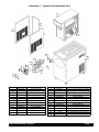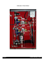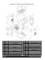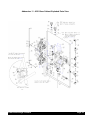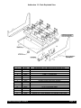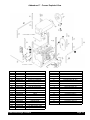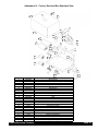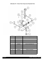
1
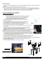
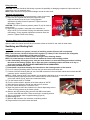
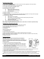
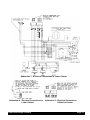
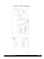
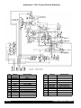
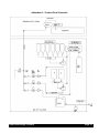
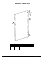
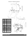
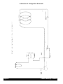
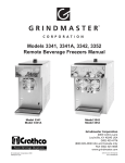
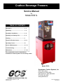
Crathco Beverage Freezers
Service Manual
for
Model 6321L
TABLE OF CONTENTS
Description........................................... 2 - 3
Unpacking............................................ 3 - 4
Assembly & Installation....................... 4 - 6
Sanitizing and Starting Unit ................ 6 - 8
Cleaning................................................. 9
Controls & Product Issues...................10 - 11
Operating Freezer..................................12
Service & Maintenance......................... 13 - 15
Troubleshooting.................................... 16
Addendums........................................... 17 - 38
Prior authorization must be obtained from
Grindmaster Crathco Systems for all warranty claims.
Model 6321L
Grindmaster Crathco Systems, Inc.
4003 Collins Lane
Louisville, KY 40245 USA
(502) 425-4776 (800) 695-4500
FAX (502) 425-4664
www.gcsworld.com
Grindmaster Crathco Systems, Inc., 2002
PRINTED IN USA
1102 Form # WH-324-03
Part # 90818
General Description
The Model 6321L is a freezer that dispenses frozen carbonated alcoholic beverages (see photo on front cover).
The freezer has two major components, the freezer sections (dispense head) and the product feed system (lower
cabinet area). The freezer consists of a freezing cylinder with a rotating internal auger (dasher) that is belt driven by
an electric motor. The auger scrapes frozen product off of the inside of the refrigerated cylinder. A torque sensing
mechanism controls compressor operation to maintain desired product consistency. The freezer has an air-cooled
refrigeration system and is mounted on a product feed base cabinet. The cabinet contains a carbonator, pumps,
interrelated tubing, and components to store, mix, and transfer carbonated liquid mix to the dispensing head.
Both the freezer and base cabinet are enclosed in independent steel cabinets. The freezer cabinet panels are easily
removed to simplify installation, service and maintenance. The base cabinet has service doors located at the front
and back for service and maintenance. Mix out indicator lights notify the operator when one or all of the product
mixes are out.
The 6311 Frozen Dispenser is the upper portion of the 6321L only.
SPECIFICATIONS
Unit Part Numbers:
Overall Dimensions
Height
Width
Depth
Operating weight: (approx.)
Shipping Weight: (approx.)
Compressor Horse Power:
Refrigeration System:
Refrigeration Type
Refrigeration Charge (See data plate)
…..Expansion valve setting
Ambient Operating Temp:
Minimum Temperature
Maximum Temperature
Electrical Requirements:
Operating Voltage
Current Draw
6321L
6311
61 1/8 in
19 ¾ in
33 5/8 in
300 lbs.
325 lbs.
¾
26 ¼ in.
13 in
28 ¾ in
150 lbs.
175 lbs.
¾
404a
.
35 PSI
404a
35 PSI
40° F
100° F
40° F
100° F
115 V
15 A
115 V
15 A
Theory of Operation
A CO2 cylinder supplies carbon dioxide gas to an adjustable carbonator regulator and an adjustable CO2 pump regulator. The pump CO 2 regulator delivers CO2 to both the gas driven alcohol pump and syrup pump. The process
starts when plain (tap) water enters a booster pump. The water is then pumped into the carbonator and carbonated.
Carbonated water flows through a manual shut-off valve to an electric solenoid that has a flow control. At the same
time, alcohol from the alcohol rack, located in the front cabinet compartment, flows to the gas driven alcohol pump.
The alcohol is then pumped through a manual shut-off valve to the alcohol electric solenoid with flow control. A gas
driven syrup pump draws concentrated syrup from the Bag-In-Box containers located at the bottom, front of the
lower cabinet. The syrup concentrate is then pumped through a manual shut-off valve to the syrup's electric solenoid
with flow control. If the freezing cylinder pressure drops below 25 PSI, the solenoids open and feed product through
a check valve into an accumulator. The carbonated water, alcohol and syrup concentrate are mixed together in the
feed line. The mixed product flows from the accumulator to the freezing cylinder.
A clear, self-closing, dispensing valve is attached to the front of the freeze cylinder barrel. A pressure release valve
is incorporated into the dispensing valve that allows excess CO2 to be vented when filling the freeze cylinder with
product. This pressure release valve will also allow excess pressure to escape the freezing cylinder.
Page 2
Crathco Beverage Freezers
The freezer is equipped with an automatic defrost system to allow the frozen product to melt back to a liquid. This
eliminates any large ice crystal formation or poor product consistency that may develop. This automatic timer can be
pre-programmed to occur at desired times of the day. The defrost cycle takes four hours to complete and should be
programmed in.
Unpacking and Inspection
Shipment and Transit
The freezer has been operated and tested at the factory. Upon arrival the complete freezer
must be thoroughly checked for any damage which may have occurred in transit. NOTE: A
Tip (N) Tell warning device is placed on each shipping carton at the factory. If the arrow tip is
blue, the carton has been tipped in transit. (See Figure 1)
IMPORTANT: The carrier is responsible for all damage in transit whether visible or concealed. DO NOT PAY THE FREIGHT BILL until the freezer has been checked for damage.
Have the carrier note any visible damage on the freight bill. If concealed damage and/or
shortage is found later, advise the carrier within 10 days and request inspection. The customer must place any claim for damage and/or shortage with the carrier. The manufacturer
cannot make any claims against the carrier.
Loose Parts Shipped with Unit
Part #
90881
90882
W0660060
W0600121
W0631903
W0600159
W0890237
W0340022
W0660300
W0480437
W0480445
W0611728
W0631230
W0660016
W0610718
W0611255
W0611086
60382
90748
90749
90750
90770
90878
W0611254
W0631549
Name
Installation Guide
Operators Manual
Plastic parts bag
Header installation instruction sheet
Sanitizer packets
Warranty card
Drip pan kit
“O” ring #213
Dow Corning Silicone lubricant
Plunger, Slush pressure
Handle, valve
Fas-Pin
Compression Spring
Silicone adhesive
Screw 5/16-18 Hex Hd
Washer, 5/16” lock
Nut, 5/16” Hex, Zinc
Heyco 1” snap bushing
Silicone Nozzle
Bottle Holddown Clamp
Adjustment Knob
90° Support
Lock Washer #10
Washer
Coke® Cleaning Fitting
Quantity
1
1
1
1
6
1
1
6
1
1
1
1
1
1
2
2
2
1
6
6
6
1
6
2
1
Figure 1
Safety and Inspection
Safety Precautions
1) Read and understand the operating instructions in this manual thoroughly.
2) Note all warning labels on the freezer.
3) Do not wear loose fitting garments or jewelry that could cause a serious accident.
4) Stay alert at all times during operation.
5) Keep operating area clean.
Do not operate freezer if any excessive noise or vibration occurs. Contact an authorized service agent.
Crathco Beverage Freezers
Page 3
Periodic Inspection
1) Check the CO2 tank pressure gauge on the cylinder regulator assembly. Replace if tank pressure drops below
red line.
2) Make sure the unit contains a sufficient supply of syrup and alcohol.
3) Check to see that there is sufficient air space on both sides of the unit. Proper air circulation is required for
efficient operation. Make sure that the louvers are not obstructed at any time. CAUTION: Failure to provide
minimum air flow clearance will void the freezer warranty. (See Locating Freezer)
Freezer Assembly and Installation
Attaching Freezer to Base Cart
1) Unbox freezer (top half)
a) Remove both side panels and then use a 7/16” socket to remove the 2
bolts at the bottom of the freezer that hold it to the shipping pallet.
b) Cut the wire tie (note red tag) on freezer drive motor. (Figure 2)
c) Leave right side panel (when facing front of freezer) off.
2) Place a bead of silicone sealant all the way around the edge of the base
cart top. (See Figure 3)
3) Place beverage freezer onto the base cabinet on top of the bead of silicone.
Position freezer over mounting holes before sealant sets. (Figure 4)
Figure 2
4) Secure top half of unit to base cart by installing 7/16" bolts and nuts using
the same holes used to secure the freezer to shipping pallet.
5) Open rear door of base cabinet and place black plastic bushing in wire hole in the top
of the cabinet.
6) Feed the 2-multi-pin connectors found in the freezer down into the base cabinet
through the hole in the top of the lower cabinet. Connect each connector from the
cabinet to matching connector in the freezer. (See Addendum 5)
CAUTION: Do not leave too much slack in the wires as they could get caught in the fan
blades. Use wire tie and holder to secure wires in place. See electrical diagram.
7) Remove the base cart electrical box cover (located in the upper right corner of the base
cart). Feed the power cord (found inside lower rear right side of freezer, near the terminals)
through hole into the base cart and then feed it into the hole in the rear of the electrical
Figure 3
box. Connect power cord wires. (See Addendum 3 and 4)
8) Route the product feed tubing (located in the freezer) down through hole into base cabinet.
Route the tubing to the top part of the freezer following the same path as the wiring.
9) Attach the tubing to the John Guest 90° elbow fitting which is located in the base cabinet behind the electrical
box. Make certain that the tubing is pushed all the way into the fitting. (Figure 5)
10) Replace freezer side panels.
11) Turn "on/off/clean" switch on front of unit to the OFF position.
90° Support
Product Feed Tubing
Figure 5
Figure 4
Page 4
Crathco Beverage Freezers
Attaching Drip Tray
1) The drip tray is mounted on two screws that are located on the lower front of the freezer cabinet.
2) Place the key hole slot of the drip tray support bracket W0471022 on to these screws and tighten the screws.
3) Angle the back of the drip tray surround bracket into the drip tray support bracket W0471022 and lower bracket
to lock it into place.
4) Place drip tray onto drip tray surround bracket.
5) Place the louvered drip tray insert into drip tray.
Locating Freezer
1. Locate freezer close to a source of potable water. Water pressure must be 15-psig or higher.
2. Connect freezer to a properly grounded 115-120 VAC, 60Hz single-phase electrical circuit with a 20-amp
(NEMA 5-20R) minimum-rated disconnect switch (not provided) that is fused at 20 amps (slow-blow).
CAUTION: Safe operation of this unit can only be achieved if the freezer is properly connected to an appropriate grounded, electrical receptacle that complies with current national safety standards. The manufacturer cannot be held responsible for damage and/or injury caused by failure to connect the unit to an appropriate source of power.
3. A minimum air clearance of 6" is required on both sides of the freezer during operation.
CAUTION: Restricting air flow through the freezer will greatly reduce the output capacity as this is an "Air
cooled" unit. Air is drawn in to cool the unit through the right side (facing front of freezer) and exhausted
through the left side. Failure to provide minimum air flow clearance will void the freezer warranty.
Connecting City Water Source Line to Unit
The National Sanitation Foundation requires the following for an NSF approved water hook-up:
• A quick disconnect water connection or enough coiled tubing so that the machine can be moved for cleaning
underneath.
• An approved backflow prevention device, such as a double check valve to be installed between the machine and
water supply. On units plumbed to permanent water line, installation of a water filter/softener system is
recommended to prevent lime and scale build-up in the machine.
• Water pipe connections and fixtures directly connected to potable water supply shall be sized, installed and
maintained in accordance with Federal, State, and Local codes.
1) Gather 3/8" OD low-density polypropylene tubing or 3/8" OD copper tubing with a
1/4” SAE Flare Connection (not provided).
2) Connect the tubing to the 1/4” SAE Flare fitting found under the left side of the
base unit. (Figure 6)
3) Connect the other end of the tubing to a water source.
NOTE: Where water quality is low an activated charcoal water filter may be needed
to achieve adequate frozen product overrun and proper flavor profile.
If water pressure exceeds 50 psig install a water regulator such as Shurflo
# 183-059-06, or equivalent, to inlet water line.
Figure 6
Installing CO2 Regulator Assembly on CO2 Cylinder
1) Unscrew protector cap (with chain attached) from CO 2 cylinder valve. Open CO 2 cylinder valve slightly counterclockwise to blow any dirt or dust from outlet fitting before installing CO2 regulator assembly, then close valve.
CAUTION: CO2 cylinders contain gas under high pressure. Handle cylinders with care.
2) Remove shipping plug from CO2 regulator assembly coupling nut, then make sure gasket is in place inside the
nut. Install hose regulator assembly on the CO 2 cylinder, then tighten coupling nut. DO NOT OPEN CO2
CYLINDER VALVE AT THIS TIME.
NOTE: Before attempting to activate the systems, insure that all manual shut-off valves, located in the lower back
compartment of the base cabinet, are closed (vertical position). Do not open them until instructed to do so.
Installing CO2 Regulator Assembly on Existing CO2 Line
NOTE: Bulk system must have 100 psi to operate.
1) Purchase a low pressure regulator set. (Norgren Model C81-570-2 recommended)
2) Disconnect carbonator and BIB pump lines. Remove existing regulator set and install low pressure set.
3) Reconnect lines to outlet side of set. Bring in bulk system line to inlet of regulator.
NOTE: Install a cutoff valve between regulator and bulk system.
Crathco Beverage Freezers
Page 5
Filling CO2 Lines
CAUTION: CO 2 lines should be filled slowly to prevent the possibility of damaging components. Open tank shut off
valve slowly until it is completely open.
NOTE: Open valve all the way to prevent leakage around the valve shaft.
Adjusting CO2 Regulators
NOTE: CO 2 regulators are pre-set at the factory. Check for accuracy.
1) Adjust the CO2 regulator that drives the bag-in-box syrup
pump and alcohol pump to 60 psi. Turning regulator
adjustment clockwise raises the pressure. Tighten locknut at
this setting. (Figure 7)
CAUTION: The use of excessive pressure (above 75 psi) will result in
pump seizure.
2) Adjust the CO2 regulator, connected to the carbonator, to
90 psi. NOTE: Do not exceed 120 psig, the carbonator pressure
relief setting. Turning regulator adjustment clockwise raises the
pressure. Tighten locknut at this setting.
Figure 7
Activating Water Source Line Connection
Open the water line manual shut-off valve in the base cabinet of the 6321L and check for water leaks.
Sanitizing and Starting Unit
Sanitizing
1) Prepare a minimum of 2 gallons (7.6 liters) of sanitizing solution (Divorsol CX or equivalent).
NOTE: Add 5 ounces (150 ml) of Divorsol CX to 2 gallons (7.6 liters) of 120° Fahrenheit (50° Centigrade)
water to achieve a concentration of 500 parts per million.
2) Disassemble the freezer following steps 1 through 8 in the Cleaning Section.
NOTE: For initial start-up, be sure to clean and sanitize the freezer before adding product.
3) After disassembly, thoroughly scour each part of the freezer in a warm mild detergent solution including
the inside of the freezing cylinder. Dip or wipe each part in sanitizing solution and allow to air dry on
clean paper toweling. DO NOT WASH COMPONENTS IN A DISHWASHER.
4) Rinse each part with clean water.
5) Reassemble components following the instructions in the Cleaning section of this manual.
6) Pour 1.5 quarts of sanitizing solution into both the front and back alcohol bottle rack.
7) Connect a red QCD cleaning fitting to one of the BIB connectors in the lower back cabinet and immerse the BIB
connector into the remaining solution.
NOTE: If a QCD cleaning fitting is not available, cut the plastic outlet fitting out of an empty BIB container.
8) Sanitize system by opening all three of the manual shut-off valves in the back
of the lower cabinet (syrup, alcohol and carbonated water).
9) Turn the freezer switch to "CLEAN".
10) Turn the control switch in the back of the base cabinet to "AUTO".
11) Allow the freeze cylinder to fill half way and run for 5 minutes.
12) Turn the freezer switch from "CLEAN" to "OFF".
13) Open the pressure relief valve located on the freezer dispensing valve to
relieve all of the pressure in the freeze cylinder.
14) Remove the QCD cleaning fitting from the first BIB line and place
it on the other BIB connection. Place second line in remaining solution.
Figure 8
15) Pull or push transfer valve to opposite setting.(Figure 8)
16) Repeat steps 9-12.
17) Remove BIB connector from container of sanitizing solution.
18) Purge sanitizer from product lines and barrel.
Page 6
Crathco Beverage Freezers
Adding Product
Connecting Syrup Supply
1) Open new bag-in-box as instructed on box.
2) Connect red QCD syrup connector to new bag-in-box.
3) Repeat for second bag-in-box.
NOTE: Make sure that the BIB lines run behind the bottle rack line so the bottle rack can be slid open easily.
Connecting Alcohol Supply
1) Remove bottle cap.
2) Slide a white tubular plastic adapter over the neck of each liquor bottle until the bottle
seats itself against the shoulder of the adapter.
3) Remove the blue plastic protective cap from reservoir port and save it.
4) Bend the nozzle of the white plastic adapter over with your forefinger to stop liquor flow.
(Figure 9)
5) Insert the nozzle of the white plastic tubular adapter into the reservoir port and allow
adapter to drop into the reservoir opening.
6) Stand inverted bottle upright.
7) Loosen the thumbscrew on the hold-down bracket and slide the hold-down bracket until it
is centered on the bottom of the bottle.
8) Push down on bracket until it firmly holds the bottle in place and tighten the knob.
Figure 9
Note: If you are using partially empty bottles place the emptiest bottle at the end of the
reservoir farthest from the reservoir outlet tubing. This will allow the partially filled bottle to be emptied first.
Activating Alcohol and Syrup System
NOTE: See Addendum 2 photo for location of components
1) Open manual valve located between gas powered alcohol pump and the alcohol electric solenoid with flow
control. This activates the alcohol supply system.
2) Open the manual valve between the gas powered syrup pump and the syrup electric solenoid with flow control.
This activates the syrup supply system.
3) Liquid should fill the lines and the pumps should cycle.
Checking BRIX (Water-to-Syrup Ratio) of Dispensed Product
NOTE: The water, syrup, and alcohol ratio are all pre-set at the factory to meet drink quality standards.
Adjustment of these ratios can only be done by authorized service technicians.
A graduated cylinder that holds at least 17 ounces (500ml) is needed to test the BRIX. A measuring cup can be
used if a graduated cylinder is not available.
1) Switch back cabinet control box switch (Figure 10) to "TEST" mode.
2) Switch Freezer control to "CLEAN".
3) Open test output port valve.
Water Ratio Check:
NOTE: See Addendum 2 for location of components.
1) Close all manual valves except the water valve.
2) Put test output port tube into the graduated cylinder.
3) Toggle "Sample Timer" switch to "ON".
4) Water will flow into the graduated cylinder for 10 seconds.
5) When water flow stops, measure the water volume in cylinder. The proper
setting is 13.5 oz. (400ml).
6) If the volume is not 13.5 oz (400ml), consult the Troubleshooting Guide in this
manual.
Figure 10
Syrup Ratio Check:
1) Close all manual valves except syrup.
2) Put test outlet port tube into the graduated cylinder.
3) Toggle "Sample Timer" switch to "ON".
4) Syrup will flow for 10 seconds.
5) When flow stops, measure syrup volume in cylinder. The proper setting is 3.7 oz. (110ml).
Crathco Beverage Freezers
Page 7
Checking BRIX (Water-to-Syrup Ratio) of Dispensed Product (cont’d)
6) If the volume is not 3.7 oz. (110 ml), consult the Troubleshooting Guide in this manual.
Note: Due to the thick viscosity of the syrup, it may be necessary to purge the syrup line to obtain an accurate flow
rate reading. Purge the syrup line by first closing the syrup valve, opening the water valve and then momentarily
turning on the test switch. This will purge all syrup from the lines and allow them to drain properly for a correct
reading of the syrup flow rate.
7) After the correct water and syrup flow rates are set, open both the water and syrup valves.
8) Turn the "TEST" switch to "ON".
9) Dispense mixed water and syrup though the test line.
10) Check the BRIX of the mix using a refractometer. Verify that the solution has a BRIX reading of 15.
Alcohol Ratio Check:
1) Close all manual valves except for "ALCOHOL".
2) Put test outlet port tube into the graduated cylinder.
3) Toggle "Sample Timer" test switch to "ON". Product will flow for 10 seconds.
4) When flow stops, measure volume in the graduated cylinder. The proper setting is 3.4 oz. (100ml).
5) If the volume is not 3.4 oz. (100ml), consult the Troubleshooting Guide in this manual.
Checking Unit for Syrup, CO 2, and Water Leaks
After checking all the ratios, open all manual valves. Open the cabinet's front and rear doors and check for any
leaks. If any leaks are located, contact an authorized service technician to fix the leak. Close and lock the front and
rear doors.
Defrost Timer
Setting Clock (Time of Day)
1) The timer is located inside the freezer back lit merchandiser box on the top front of the freezer. (Figure 11)
2) Rotate the timer dial, in the direction of the arrows, until the mark lines up with the current time of day.
3) The timer has a 2 week battery backup that requires 24 hours to charge fully.
Programming Defrost (Automatic)
1) Push all switch pin actuators toward the outer edge of the programming disk.
2) Set freeze time by pushing the switch pin actuators toward the center of the
programming disk. (Figure 11) An adequate defrost cycle should last
3-1/2 hours.
Note: Each pin actuator is equivalent to 15 minutes. Do not run a defrost for more
than 4 hours. May result in damage to seals.
Figure 11
Filling Freezer
1) Open all product manual control valves.
2) Set lower control box Power switch to "ON" and Sample Timer switch to "OFF" and Control Select switch
to “Run". (Figure 10)
3) Fill freezer with product
a. Turn freezer to "CLEAN", barrel will fill
b. When BIB pump stops switch freezer "OFF"
c. Open dispensing relief valve vent and relieve pressure. Close vent.
d. Repeat steps a-c until product reaches vent opening.
4) Switch freezer to "FREEZE" and allow approximately 15 minutes for product to reach proper frozen consistency.
NOTICE: For applications with extended periods between use (i.e. stadiums, arenas, special events) the freezer
must remain in “FREEZE” mode at all times, with a programmed defrost cycle. Turning the freezer “OFF” or unplugging it with product in the cylinder can damage the seal, resulting in product leakage. If the freezer must be
unplugged or turned “OFF”, for a period of time exceeding 12 hours, it must be drained, cleaned and sanitized.
Contact a qualified service technician, such as ICEE Company, phone (800) 423-3872, to perform this service.
Freezer damage resulting from failure to follow this procedure is not covered under warranty.
Page 8
Crathco Beverage Freezers
Cleaning
NOTE: Before cleaning, all product should be drained from the freezing cylinder, pressure vented, and either the valves set closed or product removed from the machine.
1) Disassemble the dispensing valve by first removing the dispensing valve pin
(Figure 12)
2) Push up on the dispensing valve plunger and pull out the dispensing handle.
The plunger assembly complete with spring and "O" Rings can then be removed
as a unit.
3) Remove knobs and carefully remove the freezer dispensing valve assembly.
Figure 12
4) Remove the O-Rings from the plunger assembly and back of the dispensing
valve body.
NOTE: The best way to remove an O-Ring is to first wipe off all of the lubricant using a clean
paper towel. Pinch the O-Ring upward with a dry towel between your index finger and thumb.
When a loop is formed in the O-Ring, roll it out of the groove with your other thumb. Always
remove the O-Ring farthest from the end of the plunger first. (Figure 13)
5) Carefully inspect the O-Rings for wear, nicks or cracking and replace if necessary.
6) Carefully pull out the auger assembly taking care to avoid damaging the rear seal
assembly at the back of the freezing cylinder.
7) Remove stationary portion of the shaft seal assembly (silicon carbide ring and rubber
Figure 13
boot) from the back end of the freezer cylinder. This is accomplished by reaching into
the cylinder and pulling the seal out with your index finger. (Figure 14)
8) Slide the rotary seal off of the auger shaft. (Figure 15) Inspect both seal components carefully for nicks or cracks. Replace seal if defective. NOTE: To prevent
leakage both surfaces of the seal must be smooth with no chips or cracks.
9) Wash all components in a detergent solution, sanitize and allow to air dry.
DO NOT WASH COMPONENTS IN A DISHWASHER.
10) Wet the inner rubber lip of the rotary portion of the seal and the back end of the
auger shaft with water. Slide rotary portion of assembly onto the auger shaft, RUBBER
Figure 14
FIRST, with the smooth sealing surface facing toward the back of the auger.
11) Insert the stationary portion of the seal into the grooved rubber boot with the
polished surface facing out (forward), away from the rubber boot. Lubricate the
grooved rubber exterior portion of the boot with silicone lube and insert it straight
back into recess at the back of the freezing cylinder, RUBBER FIRST.
NOTE: On the circular portion of the seal, make sure that the groove is toward the
Figure 15
rubber (back of freezer).
12) Reassemble the dasher assembly, as shown in Fig.16. Insert the larger front and
smaller rear white plastic bearings into dasher, then slip in the stator rod. Carefully
and slowly guide the auger into the freezing cylinder taking care not to
damage the seal assembly. Turn auger shaft until it engages the square drive coupling.
13) Reassemble the dispensing valve assembly. (Fig. 12) Be sure to lubricate o-rings and relief vent
before assembling.
14) Thoroughly wash and sanitize all components. Inspect and lubricate
all surfaces of the large O-Ring and refit it into the rear of the valve
assembly. Install the valve assembly on the front studs and tighten knobs
until they are finger tight. Do not use tools to tighten knobs.
IMPORTANT: Failure to lubricate the large "O" Ring can result in product
leakage.
15) Reinstall the O-Rings on the plunger assembly and lubricate the O-Rings
and plunger. Reassemble the valve and replace the retainer pin.
Daily Cleaning of Unit
Figure 16
The exterior of the unit should be cleaned as needed, at the end of the operating day or during defrost cycle.
Remember to empty and clean the drip tray and drip tray bracket.
CAUTION: Course rags, abrasive cleaners, and excessive force can damage and/or destroy the surfaces of
this unit.
Crathco Beverage Freezers
Page 9
Controls and Product Issues
Consistency Adjustment
NOTE: The following product consistency (thickness) control adjustment procedure
requires removal of the right side panel. It is suggested that a qualified service
technician make this adjustment because side panel removal exposes hazardous
moving parts.
Warning: Do not attempt freezer adjustments until electrical power has been
disconnected.
It may become necessary to readjust the consistency setting (thickness) to
compensate for variations.
1) Disconnect electrical power.
Figure 17
2) Remove right side panel (facing freezer).
3) Use the adjustment screw located on the top, front of the drive motor mounting bracket to change product
thickness. (See Figure 17).
• Clockwise for thicker product consistency.
• Counterclockwise for thinner product consistency.
NOTE: It may require up to three 180° turns of this adjusting screw to see a noticeable change in product thickness.
4) Turn freezer to "ON" and allow it to freeze to desired consistency.
5) Wait 15 to 20 minutes, check product consistency (thickness) and repeat as needed.
6) Reinstall the side panel and reconnect power.
Mix Out Lights
Red indicator lights, located on the front of the freezer, illuminate if the unit runs out of CO2, syrup, water or alcohol.
When a light is on, the unit will not fill or freeze product.
Freezer Controls
NOTE: This dispenser has several power switches, that must be set in their operating position for the unit to operate
properly.
"ON/OFF/CLEAN" SWITCH
The "ON/OFF/CLEAN" switch is a three-position toggle switch located on the front of the freezer. The left (facing the
machine) position is the "ON" or freeze position. The middle position is the "OFF" position. The Right position is the
"CLEAN" position (the auger is turning but the compressor is off).
Lower Base Control Panel Switches
All of the following switches are located on the lower control box, inside the rear cabinet door. (See Addendum 2 at
the back of the manual)
Power Switch
This is the unit’s main power switch.
• On - power is supplied to the base unit.
• Off - No power is supplied to the base unit.
Control Switch
This switch determines whether the unit is in the test mode or operating mode.
• Test - The Test switch is used to check the BRIX of the product allowing the Timer Switch to control
the solenoids.
• Off - Turns off the product feed system.
• Run - Allows product to be automatically fed to the freezer.
Timer Switch
• On - Activates the 10 second timer use to test BRIX and mix ratios
• Off - Timer is de-activated (normal operating setting).
Faceplate Relief Valves
A spring-loaded pressure relief valve maintains a safe pressure in the freezing cylinder. When filling the cylinder the
relief valve acts as a vent to allow the CO2 and air trapped in the freezing cylinder to escape. Venting the freezing
cylinder is essential to obtain proper overrun. The vent is also used to break a vacuum when draining a unit.
Dispensing Valve
CAUTION: The product in the freezing cylinder is under pressure, open the dispensing valve slowly when
dispensing product.
Page 10
Crathco Beverage Freezers
Product Quality
BRIX
Correct BRIX effects product flavor and freezing characteristics. Frozen product with low BRIX may have a weak flavor, larger ice crystals, and a tendency to dispense slowly. Product with high BRIX has an overly strong flavor,
increased portion cost and results in lower freezer output capacity.
Alcohol Content
High alcohol content may prevent the freezer from serving product at proper thickness. High alcohol also suppresses the syrups ability to absorb CO2 and depresses the temperature of the frozen product. Too much alcohol will also
lower product overrun.
What Is Overrun?
Overrun is the increase in product volume, expressed as a percentage, resulting from the carbonation of the water.
The freezer chamber is pressurized, which holds the carbonation in the frozen product. The carbonation causes the
volume of the frozen product to increase when dispensed. For example, if one gallon (4.4 liters) of liquid mix is fed
into a freezing cylinder and one and a half gallons (6.6 liters) of frozen product is drawn out, the result is a fifty percent volumetric increase, or a fifty percent (50%) "overrun".
Why is overrun important? The introduction of CO2 into the finished frozen product is essential from two standpoints...taste and profitability. Frozen product that has a low percentage of overrun costs more to serve, appears
wet, and is heavy. The introduction of CO2 makes the finished frozen product taste richer. Too much overrun causes
the finished frozen product to be too light and fluffy, making it less satisfying and adversely effecting sales.
Factors Effecting Overrun
Syrups
The foaming agent in the syrup increases the ability of the frozen product to expand as it is dispensed.
Frozen Product Draw Rate Effects Overrun
Infrequent frozen product usage can result in a drink that may appear wetter and have less overrun.
Carbonation In The Water Effects Overrun.
There is a direct correlation between the level of carbonation of the water and the overrun of the frozen drink. Water
quality has a direct effect on carbonation. If it is difficult to achieve adequate overrun an activated carbon filter will
have to be added to the system. Also try readjusting the carbonator CO2 pressure.
Computing Overrun
1)
2)
3)
4)
5)
Weigh an empty cup.
Weigh this cup filled to the rim with liquid mix, and subtract the weight of the cup.
Draw a heaping cup of frozen product that contains no air pockets. Avoid tapping the cup as this artificially
reduces overrun.
Use a straight edge to scrape off excess product flush with the rim of the cup and weigh the cup.
Subtract the cup weight and use the overrun formula to determine overrun.
Weight of
Liquid Mix
Weight of
Frozen Product
X
100 =
OVERRUN
Weight of Frozen Mix Product
For Example:
If a full cup of liquid mix weighs 23 ounces (.652kg) and a full cup of frozen product weighs 15 ½ ounces (.439kg),
then:
23 - 15½ X 100 = 48.4% Overrun
15½
Crathco Beverage Freezers
Page 11
Operating Freezer
Unit Operation
1) Check that a "Mix Out" light is not illuminated. This indicates the freezer has an adequate amount of syrup,
CO2, alcohol and water (only one light will be ON at a time). Check machine after each product is filled.
2) Insure that the "ON/OFF" switch in the lower back compartment of the cabinet is in the "ON" position.
3) Insure that the "TEST/OFF/RUN" switch in the lower back compartment of the cabinet is in the "RUN" position.
4) Insure that the "ON/OFF/CLEAN" switch on the front of the freezer is in the "ON" position.
5) Allow the freezer sufficient time to reach desired product consistency (compressor will shut off).
6) Slowly open the dispensing valve to dispense frozen product.
7) If frozen product consistency is not correct, readjust following the instructions found in the PRODUCT
CONSISTENCY section of this manual.
Replenishing Syrup Supply
A vacuum transfer valve will automatically switch from an empty BIB container to a full one. Check BIB containers on
a regular basis and replace empty BIB following the procedure in the CONNECTING SYRUP SUPPLY section of this
manual.
Replenishing CO2 Supply
1) Open rear cabinet door.
2) Turn CO2 cylinder valve clockwise until it is fully sealed.
3) Detach Regulator assembly.
CAUTION: Remove connector slowly to relieve pressure build-up in the lines.
4) Unhook S-hook from safety chain.
5) Remove empty CO2 cylinder.
6) Slowly crack the valve on the new CO2 cylinder to blow any debris out of the valve.
7) Close the valve.
8) Place new CO2 cylinder in the place of the used CO 2 cylinder.
9) Make sure that the CO 2 regulator assembly coupling nut gasket is undamaged.
10) Attach the regulator hose on the new CO2 cylinder.
CAUTION: The CO2 lines need to be pressurized slowly to insure they are not damaged. Open the tank shut off
valve slowly until it is fully open. NOTE: Opening the valve all the way prevents leakage around the valve shaft.
Replenishing Alcohol Supply
1) Remove empty alcohol bottles.
2) Remove white tubular adapters from bottles.
3) Remove caps from new bottles and slide white plastic adapter over the neck until the bottle seats itself against
the shoulder of the adapter.
4) Bend the nozzle of the white plastic adapter over with your forefinger to stop liquor flow.
5) Insert the nozzle of the white plastic adapter into the reservoir port and allow adapter to drop into the reservoir
opening.
6) Stand inverted bottle upright.
7) Loosen the thumbscrew on the hold-down bracket and slide the hold-down bracket until it is centered on the
bottom of the bottle.
8) Push down on bracket until it firmly holds the bottle in place…tighten the knob.
9) Repeat for each bottle
Note: If you are using partially empty bottles place the emptiest bottle at the end of the reservoir farthest from the
reservoir outlet tubing. This will allow the partially filled bottle to be emptied first.
Page 12
Crathco Beverage Freezers
Service and Maintenance
Quarterly Preventative Maintenance
Quarterly Preventative Maintenance is recommended to extend the life of the machine. Preventative Maintenance
visits include sanitizing the entire system, checking for and replacing any worn parts, optimizing operating
conditions. See the parts replacement schedule at the end of this section.
Sanitizing Entire Liquid Systems
It is essential that the entire liquid system be sanitized every 3 months by a qualified technician. Follow the above
instructions.
NOTE: Clean and sanitize the entire liquid system before and after storage.
Routine Product System Sanitizing
Note: During sanitizing, all "O" Rings and seals should be inspected for damage
1)
Drain product from freezing cylinder barrel
a)
Turn freezer switch to "CLEAN".
b)
Close manual syrup feed valve in back lower compartment of the cabinet.
c)
Close manual alcohol feed valve in back lower compartment of the cabinet.
d)
Place container under product dispensing valve, open dispensing valve handle.
e)
Continue to remove product until it starts to become semi-clear and has a liquid consistency.
f)
Close manual carbonated water feed valve in back lower compartment of the cabinet.
g)
Drain remaining product. If liquid flow stops before the freezing cylinder is empty pull vent (round
ring) in valve block and break vacuum.
2)
Remove product from BIB supply lines
a)
With freezer in "CLEAN" mode, disconnect BIB connectors.
b)
Open manual syrup valve in back lower compartment of the cabinet.
c)
Place a container under test line and open test port manual valve.
d)
Turn the control switch in lower cabinet to "TEST".
e)
Turn test switch to "ON".
f)
Allow pump to operate until it stops.
g)
Move BIB connector to other BIB container and repeat steps (e) and (f) above.
h)
Install a cleaning connector to BIB connector that is indicated as active by the switch on the BIB
vacuum transfer valve.
i)
Put line with connector into a container of clean water.
j)
Repeatedly cycle the "TEST" switch to "OFF" then to "ON" until the line is clear of syrup.
k)
Repeat process for alternate BIB hose starting at (g) above.
l)
When the syrup lines are clean close the manual syrup line valve.
3)
Remove product from Alcohol supply lines
a)
With freezer in "CLEAN" remove the alcohol bottles from storage rack.
b)
Open the manual alcohol valve in the back lower compartment of the cabinet.
c)
Place a container under test line and open manual test port valve.
d)
Move control switch in lower cabinet to "TEST". Turn test switch to "ON".
e)
Allow pump to operate until it stops or all alcohol is removed.
f)
Pour clean water into the alcohol rack reservoir .
g)
Cycle the test switch from "OFF" to "ON" until the line is clear of alcohol.
h)
When lines are clean close the manual valve on alcohol line.
Complete the sanitizing procedure by following the steps in the Sanitizing & Starting Unit Section.
Servicing Dispensing Valves, O-Rings, and Freeze Cylinder Drive Shaft/Seal Assemblies
NOTE: Dispensing valve "O" Rings should be replaced every 120 days to correspond with quarterly preventative
maintenance visits.
The best technique for removing an "O" Ring is to first wipe off all of the lubricant using a clean paper towel. Pinch
the "O" Ring upward with a dry towel between your finger and thumb. When a loop is formed in the "O" Ring, roll it
out of the groove with your thumb. Always remove the "O" Ring farthest from the end of the plunger first. (See
Figure 13)
Crathco Beverage Freezers
Page 13
Lubricating Plunger O-Rings
1)
2)
3)
4)
5)
6)
Close syrup and alcohol manual control valves located in the back compartment of the lower cabinet.
Place freezer in "CLEAN" position.
Drain freeze cylinder while purging with carbonated water.
Turn freezer control switch to the "OFF" position.
Vent pressure and drain completely.
Remove dispensing valve plunger.
a)
Remove valve handle retaining pin.
b)
Push plunger up and remove handle.
c)
Pull plunger down.
7) Remove "O" Rings and clean "O" Ring grooves.
8) Replace "O" Rings.
9) Lubricate the "O" Rings on the plunger and the area inside of the clear plastic valve body where the plunger
"O" Rings make contact with the valve body using silicone lubricant.
10) Replace Plunger assembly.
a)
Place spring on top of plunger.
b)
Place plunger in valve body making sure that the handle opening faces forward.
c)
Push up on plunger and replace handle.
d)
Insert handle retaining pin.
e)
Sanitize unit following instructions in manual.
11)
Refill unit following instructions in manual.
Note: Plunger o-rings, face plate quad ring, shaft seal set, motor belt, etc. should be replaced annually.
Changing Back Lit Sign Merchandiser Bulb
1)
2)
3)
4)
5)
Remove the two screws, located on the top on either side of the sign.
Lower the metal enclosure that frames the merchandiser insert.
Pull merchandiser enclosure down and out.
Replace bulb inside.
Reassemble.
Cleaning Condenser Coil
1) Turn machine "OFF".
2) Remove both freezer side panels.
3) Place a wet towel on the inlet side of the condenser (right side facing front of freezer).
4) Use compressed air to blow out condenser coils from the exhaust side of condenser coil (fan motor side).
NOTE: Follow all health and safety standards.
5) Replace side panels.
Drive Belt Adjustment
CAUTION: Unplug the machine before performing any adjustments.
Check the belt tension quarterly. Proper belt tension is ½" deflection
measured mid way between the drive and driven pulleys. If the deflection is
more than ½" adjust the motor height to achieve proper tension using the
following procedure:
1) Unplug the unit and remove the side and rear panels.
2) Locate the motor flange bearings (W0380009) located at each end of
the drive motor. Two bearings support the motor, one on the shaft at
each end of the motor. The bearings are secured to the motor cradle
using two Allen bolts on each bearing.
3) Loosen all four bearing Allen bolts. NOTE: Do not loosen the setscrews
Figure 18
that hold the bearing collars to the motor shaft.
4) Lower or raise the motor as needed to achieve proper belt tension. The motor must be kept level from front
to back. NOTE: Excessive belt wear and belt noise can occur if the motor is not kept level.
5) Tighten all four Allen bolts down.
6) Align the driven motor pulley with the top driven pulley if needed. Use a straight edge along the top pulley. If the
pulleys are not in alignment, remove the setscrew from the pulley and move either in or out as needed.
NOTE: Use non-permanent Loc-Tite on the driven pulley setscrew and tighten down on the flat of the motor shaft.
Page 14
Crathco Beverage Freezers
Parts Replacement Schedule
Part Description
Monthly
Drive shaft seal
W0340210
Drive shaft
W0451067
Drive belts
W0450209
Scraper blades
on dasher
W1431084
Square cut o-ring on
valve body/face plate
W0340055
Every
3 Months
Inspect & replace
if necessary
Crathco Beverage Freezers
Annually
Quantities to
be Replaced
Replace
1
Inspect & replace
if necessary
Inspect & replace
if necessary
1
Replace
Front stator flange
bearing
W0430032
Rear stator flange
bearing
W0430024
Dispense valve o-rings
W0340022
Dispense valve
relief valve
W0650429
Inlet tube o-rings
W0340011
Condenser
W0200256
Alcohol Holder
components
90750 - knob
90749 - clamp
90748 - nozzle
Alcohol, syrup, &
water solenoid 90863
Alcohol, syrup pump
90729 and
Water pump 61290
Alcohol rack
Every
6 Months
2
Inspect & replace
if necessary
1
Inspect & replace
if necessary
1
Inspect & replace
if necessary
1
Replace
3
Inspect & replace
if necessary
1
Inspect & replace
if necessary
Inspect & clean if
necessary
Inspect & replace
if necessary.
1
2
1
Nozzle
replacement
mandatory.
6
Inspect & replace
3
if necessary
Inspect & replace 2 - CO2 Driven,
if necessary
1 - Electric
Disassemble and
sanitize
Page 15
Troubleshooting Guide
If machine is not operating properly, check the following list for possible solutions. Only a qualified service technician
should perform electrical and mechanical adjustments or repairs. Always disconnect power before attempting any
maintenance procedures.
Problem
Machine won’t run (no lights,
not motor)
Probable Cause
•
•
Machine will not freeze
•
•
•
•
•
•
•
•
•
•
• Plug machine directly into outlet. Do not
use extension cord.
• Place circuit breaker in the ON
Building circuit breaker tripped or fuse
position or replace fuse
blown
• Turn lower panel Power Switch to ON,
Switches in wrong position
Control Switch to OFF and freezer switch
to ON.
Dasher assembly not installed
• Install dasher assembly
Drive belt broken or off pulley
• Repair or replace
Inadequate airflow
• Allow 6” (15cm) on both sides
Freezer in CLEAN position
• Switch to ON
Mix low light on indicating an out of condition • Correct out of condition (syrup, water,
alcohol, or CO2 )
• Clean condenser
Condenser clogged
• Check for cause and correct
Compressor not operating
• Check for leaks, repair and recharge
Low refrigerant charge
• Adjust within specifications
Improper expansion valve setting
• Wait for defrost cycle to end
Defrost timer set
Product too soft (thin)
• Consistency adjuster too thin
• Too much alcohol
• Product BRIX level too high
Product too thick (firm)
• Consistency adjuster set too firm
• Too little alcohol
Product will not dispense
Leakage from drip tube
•
•
•
•
•
Product BRIX level too low
Power switch OFF
MIX LOW light on
Drive belt broken or off pulley
Worn out or defective drive shaft seal
Excessive Dispensing Valve
Leaks
Clicking sound from inside the
machine
• Worn or defective o-ring(s)
Thumping sound from inside the
machine
Product does not feed
•
•
•
•
•
•
Premature seal wear
Remedy
• Machine not plugged into wall receptacle
• Low voltage
• Extension cord is used
Worn belt
Low alcohol content
Low CO2 pressure
Product pumps defective
Carbonator pump defective
Transformer defective or transformer
overload tripped
• Solenoids defective
• Incorrect installation of dasher
• Improper drive shaft clearance
• Readjust consistency firmer
• Readjust alcohol flow control
• Check water and syrup flow controls for
proper test volume
• Readjust consistency setting thinner
• Increase product BRIX level and check
product feed
• Increase product BRIX level
• Turn power switch ON
• Refill empty product
• Repair or replace
• Replace seal and then lubricate at each
cleaning
• Replace and lubricate at each cleaning
• Use dedicated circuit with proper rating
• Connect directly to power source or use
power cord of proper size
• Replace belt
• Check mix
• Check bottle and regulator
• Replace pumps
• Replace pumps
• Replace transformer or reset transformer
circuit breaker
• Replace solenoids
• Advise careful installation
• Adjust to proper clearance
If you still need help, call an authorized dealer in your area or GCS’ Technical Service Department. You can reach
Technical Service at (800) 425-4776 Monday-Friday, 8:00 AM-6:00 PM Eastern Standard Time. Please have the model and
serial number ready so that accurate information can be given.
Prior authorization must be obtained from Grindmaster Crathco Systems’ Technical Service Department for all
warranty claims.
Page 16
Crathco Beverage Freezers
Addendum 1 - Complete Unit Exploded View
1
11
11
11
28
25
28
10
8
9
12
14
16
23
10
24
15
ITEM
1
2
4
5
6
7
8
9
10
11
12
13
14
PART #
W0150590
00800
W0800120
W0800121
W0800122
W0800124
W0340210
W0430089
W1431084
W0890235
W0340055
W0610133
W0480460
DESCRIPTION
Stock Assembly
Serial Label
Base Board Assembly
Shipping Box
L-Block
Foam Top Carton Pad
Coconut Oil Seal
Scraper Dasher
Scraper Blade
Kit, Panel Black
O-ring, Valve Body
Panel Screws
Body, Valve Pressure
Crathco Beverage Freezers
ITEM
15
16
17
18
19
21
22
23
24
25
26
27
28
29
PART #
W0630711
W0650429
W0631238
W0610574
W0611074
W0611242
86823
W0430024
W0430028
W0430032
60832
90822
90719
W0660058
DESCRIPTION
D-Knob, w/ 5/15-18 Female Threads
Pressure Relief Valve, Modified
Spring, Extension Yellow
1/4-20 Hex Head Cap Screw
1/4-20 Hex Nut
Flat Washer
1/4 Lock Washer
Stator Flange Bearing (Rear)
Stator Weldment
Stator Flange Bearing (Front)
Bushing, Heyco 1” Snap
Patent Pending Label
Cart, Carbonated Alcohol Injected
Plastic Shipping Bag
Page 17
Addendum 2 - Base Cabinet
Regulators
POWER
OFF
ON
SAMPLE TIMER
OFF
ON
CONTROL SELECT
RUN
TEST
OFF
Alcohol Valve/Control
Syrup Valve/Control
Test Port
Water Valve/Control
Carbonator
Water Pump
Page 18
Crathco Beverage Freezers
29
28
64
59
63
WHT / BLK
YELLOW / BLK
BLACK / WHT
58
62
60
VIOLET / WHT
VIOLET / WHT
31
35
57
27
64
62
59
63
31
57
35
60
58
62
Addendum 4 - Electrical Connections in
Lower Cabinet
Crathco Beverage Freezers
60
58
62
59
63
64
35
57
31
Addendum 3 - Electrical Connections in Lower Cabinet
Addendum 5 - Electrical Connections
Cabinet to Freezer
Page 19
Addendum 6 - 6321 Base Cabinet Electrical Schematic
28
29
27
60
64
57
63
35
31
59
62
58
30
19
15
21
20
30
33
64
18
34
30
32 62
27
23
32
24
14
21
62
59
45
32
17 16
29
33
23
24
22
25
28
25
63
24
61
13
37
18
38
33
34
17
39
16
15
26
14
36
12
40
13
11
57
35
31
60
10
58
44
7
9
6
7
8
62
8
42
Page 20
42
43
41
ITEM
PART NUMBER
DESCRIPTION
30
W0570045
BALLAST
61
W0570235
90811
TERMINAL BLOCK
32
33
61847
POWER SWITCH
34
61847
TIMER SWITCH
45
36
SWITCH
FLOAT SWITCH
37
W0570924
COMES WITH
CARBONATOR
90834
38
W0570044
LIGHT SOCKET
39
W0570043
LIGHT BULB
40
90857
SYRUP AND ALCOHOL SOLENOIDS
41
W0650415
SOLD OUT SWITCH
42
W0650400
BARKSDALE PRESS. SWITCH # MSPS-JJ100SS-F
43
90858
WATER SOLENOID
44
90879
ALCOHOL FLOAT SWITCH
TIMER
PUMP
Crathco Beverage Freezers
Addendum 7 - 6321L-A Ladder Diagram
Crathco Beverage Freezers
Page 21
Addendum 8 - 6321 Freezer Electrical Schematic
14
75
63
74
69
19
76
69
18
1
40
25
37
58
38
1
6
64
13
24
2
3
10
9
36
12
41
10
2
39
22
19
50
23
27
21
33
12
11
5
13
4
5
26
18
11
49
3
27
26
32 68
15
9
25
69
28
55 74
31
48
8
8
29
16
30
73
33
55
35
45
34
34
57
55
77
55
28 30
17
66
32
47
46
65
20
76
75
16
20
53
77
24
22
49
50
23
15
54
59
21
17
61
6
16
60
70
14
62
31
28
35
59
57
58
64
29
60
62
63
27
ITEM
LENGTH
DESCRIPTION
ITEM
LENGTH
DESCRIPTION
72
71
70
69
67
56
55
54
53
52
51
48
47
W0570662
W0570661
W0570682
W0570242
60110
60034
60033
85303
W0650407
W0650121
W0650011
W0570924
W0570043
RELAY SOCKET
RELAY
TIMER
SPLICE CAPS
PIGGYBACK TERMINAL
LIGHT, AMBER
LIGHT, RED
RELAY
PRESSURE SWITCH
LOW PRESSURE SWITCH
SOLENOID VALVE
SWITCH
FLUORESCENT LIGHT BULB
46
45
44
43
42
41
40
39
38
37
36
W0570044
W0570045
W0630801
W0572050
W0572192
W0570604
W0570603
W0570235
W0570651
W0570656
W0570638
LIGHT SOCKET
CORE & COIL BALLAST
TIE WRAPS
POWER CORD
LOW MIX SUB-ASSY
RUN CAPACITOR
START CAPACITOR
TERMINAL BLOCK
TIME DELAY RELAY
TRANSFORMER
COMPRESSOR RELAY
Page 22
Crathco Beverage Freezers
Addendum 9 - Product Flow Schematic
Crathco Beverage Freezers
Page 23
Addendum 10 - 6321 Base Cabinet Panels Exploded View
ITEM
1
2
3
4
5
6
7
8
9
10
11
12
13
14
15
PART NO.
90780
90727
90746
90827
90724
90829
90830
90831
90728
86600
07348-1
62486
W0570205
W0570207
W0570242
Page 24
DESCRIPTION
PANEL, BOTTOM ASSY, BASE CART
PANEL ASSY, INTERIOR, BASE CART
ALCOHOL HOLDER
TOP PANEL ASSY
RIGHT SIDE PANEL ASSY
LEFT PANEL ASSY
DOOR ASSY
REAR DOOR ASSY
PLASTIC COSMETIC COVER
TIE, WIRE, NYLON, T18R (NOT SHOWN)
POP RIVET
DECAL, GCS LOGO - 4 X 1.25
TERM, 2-520103-2.250 FASTON- (NOT SHOWN)
TERM, FASTON 16-14 GA FULLY (NOT SHOWN)
SPLICE CAP, INSULATED (NOT SHOWN)
ITEM
16
17
18
19
20
21
PART NO.
DESCRIPTION
W0570272
TERM, RING EYE (NOT SHOWN)
W0660060
BAG, PLASTIC, 12 X 10
W0631809
VELCRO, HOOK
W0631810
VELCRO, LOOP
W0600031
LABEL, SERVICE, ICEE
90847
LOOSE SHIPPED PARTS KIT (NOT SHOWN)
22
23
24
25
26
00800
90818
82085
W0610923
61339
LABEL, SERIAL NUMBER, NAME PLATE
MANUAL, SERVICE, 6321L
8-32 UNF S.S. ACORN NUT
PEM STUD, 8-32 X 3/8”
8-32 UNF S.S. ACORN NUT
27
28
60593
60550
CLAMP, 1/2 STEPLESS
CLAMP, 11/16 STEPLESS
29
30
W1631510
WIRE TIE HOLDER
W1631508 SADDLE WIRE, ALL STATES (NOT SHOWN)
Crathco Beverage Freezers
Addendum 11 - 6321 Base Cabinet Exploded Parts View
Crathco Beverage Freezers
Page 25
6321 Cabinet Exploded Parts View
ITEM
1
2
3
4
5
6
7
8
9
10
11
12
13
14
15
16
17
18
19
20
21
22
23
24
25
26
27
28
29
30
31
32
33
34
35
36
37
38
39
40
41
42
43
44
45
46
47
48
49
50
51
Page 26
PART NO.
DESCRIPTION
90726
PANEL, INTERIOR-BASE CART
90729
SYRUP PUMP
90730
FITTING, SHURFLO TO 3/8” JOHN GUEST
90875
SWITCH, PRESSURE, BARKSDALE-40 PSI
W0620283
ADAPTER, 1/8” FPT X 3/8” STEM
90857
VALVE, FLOMATIC 424 DUAL SYRUP PISTONS (P/N 407-CSY-D22)
90858
VALVE, FLOMATIC 424 SINGLE SODA PISTON AND PLUG (P/N 407-CF-D22-R)
90855
FLOMATIC VALVE MNT BLOCK 380 Q
90854
FITTING, 3/8 PLUG-IN ELBOW
90859
FLOMATIC VALVE MNT BRACKET
90860
FITTING, MALE CONNECT-1/4” X 1/4” MFL (JG# PIO108F4S)
90758
CHECK VALVE
90767
FTG, 1/4 SAE X 3/8 JG# PI4512F4S
W0340120
RUBBER GROMMET
90763
FITTING, 3/8” ELL JG# 1032-S
90764
FITTING, 3/8 PLUG-IN ELBOW
W0620282
TEE, 3/8 X 3/8 X 3/8 TUBE
W0650123
CHECK VALVE, JG
90733-3.000
TUBING, LOW DENSITY POLYETHYLENE 3”
90733-8.0
TUBING, LOW DENSITY POLYETHYLENE 8”
90733-3.375
TUBING, LOW DENSITY POLYETHYLENE 4”
90733-2.0
TUBING, LOW DENSITY POLYETHYLENE 2”
60591-10.00
TUBING, 1/4” BRAIDED 10.00”
60591-2.25
TUBING, 1/4” BRAIDED 2.250”
90869
FITTING, 1/4” X 1/4” X 1/4” BARB TEE
90868
FITTING, 1/4” X 1/4” ELL BARB, CHUDNOW (P/NS29-M44U)
60593
CLAMP, 1/2 STEPLESS
90743
VALVE, AUTOMATIC, BIB, SELECTOR
90813
BRKT, BIB SELECTOR SWITCH
90781
SCREW, #4 X 1/4 SM,P (MNTG ITEM #33 - NOT SHOWN)
90745
VALVE, 3/8 JG# PSV0412CS
90733-10
TUBING, LOW DENSITY POLYETHYLENE - 10.0”
90770
SUPPORT, 90 TURN JOHN GUEST # PM2610S
61153-10
BRAIDED TUBING, 10.0”
61153-42
BRAIDED TUBING, 42.0”
60550
CLAMP, 11/16 STEPLESS
82085
8-32 UNF S.S. ACORN NUT
90824
DECAL, ALCOHOL
90825
DECAL, SYRUP
90826
DECAL, CARBONATED WATER
90863
SOLENOID, DUAL CONTROL (FLOMATIC P/N 770-D22) (NOT SHOWN) SPARE PARTS
61288
8-32 X 7/8” PH PN BLK SCREW
90885
HEYCO BUSHING, BACK (P/N 2853)
90886
INSERT, TAMPER PROOF (FLOMATIC P/N 1025) - NOT SHOWN
90733-2.500
TUBING, LOW DENSITY POLYETHYLENE 2.50”
90733-4.000
TUBING, LOW DENSITY POLYETHYLENE 4.00”
61153-26
BRAIDED TUBING, 26.0”
61153-28
BRAIDED TUBING, 28.0”
90774
FITTINGS, BIB COKE
W0600013
DECAL, INDEMNITY CLAUSE
W0600035
LABEL, WARNING, TAMPERING
Crathco Beverage Freezers
Addendum 12 - Rack Exploded View
ITEM NO.
1
2
3
4
5
6
7
8
9
10
11
12
13
14
15
16
17
PART NO.
90751
90752
90794
61153
60550
90802
90850
90799
90800
07023-04
90747
90877
60012
90748
90749
90750
90878
Crathco Beverage Freezers
DESCRIPTION
MNT BRACKET, LEFT, BERG ALCOHOL HOLDER ASSY
MNT BRACKET, RIGHT, BERG ALCOHOL HOLDER ASSY
3/8” X 3/8” X 3/8” BARB TEE
TUBING, BRAIDED .375” ID X .625” OD X 2.5” L
CLAMP, 11/16 STEPLESS
DRAWER SLIDE MNT. BRACKET, RIGHT
6-32 UNF S.S. ACORN NUT
DRAWER SLIDE, LEFT (NOT SHOWN)
DRAWER SLIDE, RIGHT (NOT SHOWN)
SCREW, 6-32 X 1/4” PH BD M/S - S.S. (NOT SHOWN)
BERG ALCOHOL HOLDER ASSY
ASSY, 3 BOTTLE RESERVE WITH FLOAT SWITCH-MODEL #8000200
1/4-20 X 1/2” ROUND HEAD
RESERVE NOZZLE
ADJUSTABLE BOTTLE CLAMP
THUMBSCREW, ADJUSTABLE BOTTLE CLAMP
WASHER, #10, LOCK, INTERNAL, NOT SHOWN - SHIP LOOSE
Page 27
Addendum 13 - 6321 Cabinet Base Exploded View
Page 28
Crathco Beverage Freezers
6321 Cabinet Base Exploded View Key
ITEM
1
2
3
4
5
6
7
8
9
10
11
12
13
14
15
16
17
18
19
20
21
22
23
24
25
26
27
28
29
30
31
32
PART NO.
90723
W0630900
W0630898
W0611086
W0611255
W0650415
90873
90874
W0620278
W0620282
90733-23.250
90776
61290
90786
W0611042
W0611235
90770
W0570105
61479
82085
90761
90777
71237
61153-6
60550
60591
60593
90782
60797
90783
83759
W0631008
Crathco Beverage Freezers
DESCRIPTION
PANEL, BOTTOM-BASE CART
CASTER, RIGID-TWIN BASE CART
CASTER, SWIVEL-TWIN BASE CART
NUT, 5/16-18 HEX ZINC
WASHER, 5/16 LOCK
SWITCH, SOLD OUT, 8-30 PSI
ANCHOR COUPLING PARKER P/N 207ACBH-4
MALE ELBOW PARKER P/N 149F-4-4
ADAPTER, 1/4 NPT X 3/8 STEM
TEE, 3/8 X 3/8 X 3/8 TUBE
POLYETHYLENE TUBING, 23.250”
FITTING, 3/8 MPT X 3/8 MPT JG#P14812235
CARBONATOR, PUMP SHURFLO
3/8 MPT X 3/8 SAE, BRASS
NUT, 8-32 NYLON INSERT ZINC
WASHER, 3/16 SAE FLAT, 7/32 ID
SUPPORT, 90 TURN JOHN GUEST # PM2610S
POWER CORD, 14/3, #02-520,11’
STRAIN RELIEF, HEYCO
8-32 UNF S.S. ACORN NUT
TANK RETAINER ASSY
CARBONATOR, McCANN STANDARD NEW PROBE
FITTING, 1/4” BARB X 1/4” FF SWVL
BRAIDED TUBING 6.0”
CLAMP, 11/16 STEPLESS
TUBING, 1/4” BRAIDED, 14 3/4”
CLAMP, 1/2 STEPLESS
FTG, 3/8 SAE X 3/8 JG # PI4512F5S
GASKET, 1/4 COPR FLARE 45 DEG
FITTING, 3/8 TUBE X 3/8 SAE ELL
10-32 RIVNUT
WASHER, BONDED NEOPRENE
Page 29
Addendum 14 - 6321 Base Cart Top Panel Exploded View
ITEM
1
2
3
4
5
6
7
8
PART NO.
90722
90840
W0570043
W0570044
90835
90807
90810
90836
DESCRIPTION
PANEL, TOP-BASE CART
REGULATOR ASSEMBLY
BULB, FLUORESCENT
SOCKET, LIGHT-LEVITON
ELECTRICAL ASSY
WIRING HARNESS - BROWN FOREMAN
ELECTRICAL BOX, BASE CART
ELECTRICAL BOX COVER, BASE CART
9
82086
8-32 UNF S.S. ACORN NUT
10
W1631508 SADDLE WIRE, ALL STATES - (NOT SHOWN)
90850
90812
6-32 UNF S.S. ACORN NUT
PROTECTIVE LIGHT COVER
9
10
9
2
9
9
8
8
4
9
9
3
1
12
11
12
Page 30
Crathco Beverage Freezers
Addendum 15 - 6321 Front Cabinet Door
ITEM
PART NO.
DESCRIPTION
1
90721
DOOR, FRONT-BASE CART
2
90851
DOOR HINGE, STANDARD DUTY
3
W0610923
PEM STUD, 8-32 X 3/8”
4
61339
8-32 UNF S.S. ACORN NUT
5
90760
INSERT, OVAL
6
7
90870
90871
TAPE, 3/64 X 1/2, DBL CTD NEOPRENE
PAWL/CAM LATCH-SOUTHCO P/N 24-20-812-35
Crathco Beverage Freezers
Page 31
Addendum 16 - Rear Door and Key
3
2
4
1
5
ITEM NO.
1
2
3
4
5
Page 32
PART NO.
90720
W0610921
61339
90851
90771
DESCRIPTION
DOOR, REAR-BASE CART
PEM STUD, 8-32 X 1/4”
8-32 UNF S.S. ACORN NUT
DOOR HINGE, STANDARD DUTY
LOCK, DOOR-REAR
Crathco Beverage Freezers
Addendum 17 - Freezer Exploded View
110
160
10
30
40
A
130
150
150
60
150
170
170
170
170
160
80
ITEM
10
20
30
40
50
60
70
80
90
100
110
120
130
140
150
160
170
180
190
200
210
PART #
W0610682
W0611254
W0611255
W0611086
W0201191
W0620103
W0650119
W0110013
W0611085
W0201192
W0450053
W0610646
W0450209
W0600029
71373
W0670008
W0570018
W0600230
W0620106
W0201008
W0201006
150
DESCRIPTION
5/16-18 x 3/4 Hex Hd Cap Screw
5/16 Flat Washer
5/16 Split Lock Washer
5/16-18 Hex Nut Z/P
Suction Line Pressure
3/8 Copper Couple
Thermostatic Expansion Valve
Valve Studs
5/16-18 SS Hex Nuts
Air Baffle Side Piece
10” Pulley
5/16-18 x 3/8 Socket Hd Set SC
V-Belt
Motor Serial Plate
Nylon Screw Anchor
Trim-Lok Rubber Strip
Indicator Light
On-Off-Clean Label
Tee, 1/2 x 3/8 x 3/8 Copper
Low Side Process Tube
High Side Process Tube
Crathco Beverage Freezers
140
ITEM
A
B
C
D
E
G
H
I
J
K
L
M
N
O
P
Q
R
S
160
SOLDER CONNECTIONS
To suction line, Item G
From Item “B” to Item “E”
To TXV Item “K”
Connects Items “F”, “M” & “S”
Connects Items “B” & “L”
Connects to Item “J”
Connects to Item “R”
Connects to Item “N”
Connects to Item “G”
Connects to Item “C”
Connects to Item “E”
Connects to Item “D”
Connects to Item “I”
Connects to Item “A”
Connects to Item “Q”
Connects to Item “P”
Connects to Item “H”
Connects to Item “D”
Page 33
Addendum 18 - Freezer Base Exploded View
Page 34
ITEM
Part #
Description
1
W0201001
Compressor Assembly
2
W0201000
Condenser Assembly
3
W0320129
Fan Sub-Assembly
4
W0321026
Drive Motor Assy.
5
W0210106
Base Pan Assy.
6
W0611410
Rivet, Magna-Lok
7
W0611247
1/4 Int. Tooth Lk. Wshr.
8
W0611074
1/4-20 Hex Nuts
9
W0611082
5/16-18 Flange Nut
10
W0200412
Compressor Spacer
11
W0200413
Compressor Grommet
12
W0210104
Frame Assembly
Crathco Beverage Freezers
Addendum 19 - Freezer Electrical Box Exploded View
20
23
20
13
14
16
20
20
11
3
1
7
22
2
19
3
19
3
4
4
10
3
21
10
21
21
5
8
9
ITEM
1
2
3
4
5
6
7
8
9
10
11
12
13
14
15
16
17
18
19
20
21
22
23
24
PART #
W0570603
W0570617
W0630006
W0630811
W0570638
W0572409
W0570656
W0570235
W0570660
W0570600
W0570682
W0572407
W0572408
86805
W0610131
61532
86600
W0572530
83248
W0610127
71373
W0570242
W0600218
W0572390SH2
Crathco Beverage Freezers
6
DESCRIPTION
Start Capacitor
Run Capacitor
Heyco Bushing
Clip, Capacitor (small)
Compressor Relay
Relay Bracket
Transformer 4000-01515K999
Terminal Block
Heat Sequencer, Products Unlimited
Relay
Timer
Electrical Box
Electrical Box Cover
6-32 x 1 Screw
8-32 x 1-4 Screw
6-32 Nylon Lock Nuts
Cable Tie
Wire Harness
6-32 x 1/4 Screw
#8 Type AB Point S.S. Truss HDNylon Screw Anchor
#8 Nylon Screw Anchor
Closed End Splice Cap, AMP #55929-1
Risk of Electrical Shock Label
Elec. Wiring Ref. Drawing 6321 L
Page 35
Addendum 20 - Product Feed Components Exploded View
Page 36
ITEM
PART #
DESCRIPTION
1
W0340011
#115 O-ring (Carburetor)
2
W0471115
Pressure Inlet Fill
3
W0471118
Pressure Inlet Fill Retainer
4
W0650400
Press Switch MSPS - JJ100SS-F
5
60552
Accumulator
6
W0620282
Tee, 3/8 Tube John Guest
7
W0620285
3/8 NPT x 3/8 NPT Stem J/G
8
W0620280
Adapter, 1/2 NPT x 3/8 Tube
9
90763
Elbow, 3/8 Tube x 3/8 Tube
10
90764
Elbow, 3/8 Stem x 3/8 Stem
11
90733
Tubing, LDPET, .250ID x .375OD
12
W0620283
1/8 NPT x 3/8 J/G Stem
13
90733
Tubing, LDPET, .250ID x .375OD
14
90733
Tubing, LDPET, .250ID x 375OD
15
W0610131
8-32 x 1/4 Self Tap Screw
Crathco Beverage Freezers
Addendum 21 - Refrigeration Components
ITEM
Part #
Description
1
W0650501
Access Valve
2
W0650112
Filter Drier
3
W0201191
Suction Line
4
W0200123
Compressor
5
W0200256
Condenser
6
W0201009
Hot Gas Line
7
W0650119
8
Thermostatic
Expansion Valve
Evaporator Line
9
Suction Line
10
W0620105
1/4” Street Elbow
11
W0620102
1/4” Tee
12
W0201011
Coolant Line
13
W0201012
Coolant Line
14
W0201013
Coolant Line
15
W0620112
3/8” Copper Elbow
16
W0201153 90 Deg. Bell Reducer
17
W0201151
18
W0620103
3/8” Condenser
Connection
3/8” Coupling
Crathco Beverage Freezers
Page 37
Addendum 22 - Refrigeration Schematic
Page 38
Crathco Beverage Freezers
NOTES
Crathco Beverage Freezers
Page 39
Cocktail Machine Indemnity
The Purchaser and/or Lessee hereby releases the manufacturer of this machine, Grindmaster Crathco Systems, Inc.
(the Company), any and all alcohol and non-alcohol product companies, the Company’s officers, agents, employees,
directors, shareholders, affiliates, successors, and assigns, and shall indemnify and hold them wholly harmless from,
any and all claims, actions, suits, proceedings, demands, damages, costs, expenses, and liabilities of whatever
nature, including without limitation Company’s reasonable attorneys’ fees and expenses, relating to or in any way
arising out of operation or dispensing of beverages from this machine.