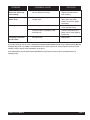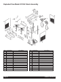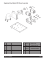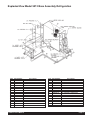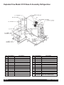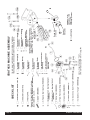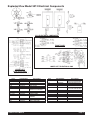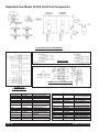
1
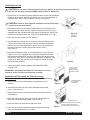
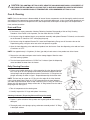
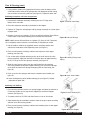
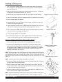
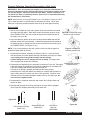
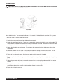
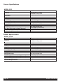
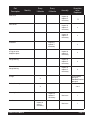
Crathco® Beverage Freezers
Operation and Instruction Manual
for
Models 5512 & 5512E
TABLE OF CONTENTS
Operator’s Safety Precautions . . . . . . . . . . . . .3
Installation . . . . . . . . . . . . . . . . . . . . . . . . . . .3-5
Operation . . . . . . . . . . . . . . . . . . . . . . . . . . .6-8
Product Tips . . . . . . . . . . . . . . . . . . . . . . . . .8-9
Consistency Control . . . . . . . . . . . . . . . . . .9-10
Care & Cleaning . . . . . . . . . . . . . . . . . . . .11-15
Maintenance . . . . . . . . . . . . . . . . . . . . . . .15-16
Adjustments . . . . . . . . . . . . . . . . . . . . . . . . . .17
Freezer Specifications . . . . . . . . . . . . . . . .18-19
Troubleshooting Guide . . . . . . . . . . . . . . .20-21
Exploded Views . . . . . . . . . . . . . . . . . . . . .22-30
Wiring Diagrams . . . . . . . . . . . . . . . . . . . .31-41
Refrigeration Schematic . . . . . . . . . . . . . . . . .42
Model 5512
Prior authorization must be obtained from
Grindmaster Corporation for all warranty
claims.
Grindmaster Corporation
4003 Collins Lane
Louisville, KY 40245-1643
Phone (502) 425-4776
800-695-4500 (USA & Canada only)
(800) 568-5715 (technical service only)
Fax (502) 425-4664
www.grindmaster.com
© Grindmaster Corporation, 2000
PRINTED IN USA
0106 Form #WH-332-04
Part #W0600138
Operator's Safety Precautions
1.
2.
3.
4.
5.
6.
Read and understand the operating instructions in this manual thoroughly.
Note all warning labels on the freezer. If any warning labels are missing or damaged replace them immediately.
Do not wear loose fitting garments or jewelry which could cause a serious accident.
Stay alert at all times during operation.
Keep operating area clean.
Do not operate freezer if any excessive noise or vibration occurs. Contact your authorized service agent.
Installation
Shipment & Transit
The freezer has been operated and tested at the factory. Upon arrival the complete freezer must be thoroughly
checked for any damage which may have occurred in transit.
Note: A Tip (N) Tell warning device is placed on each shipping carton at the factory. If the arrow tip is blue, the carton
has been tipped in transit.
Removal from Carton and Pallet
1. Remove staples or cut cardboard box around the stapled area.
2. Pull the cardboard box up off machine.
3. Remove the Styrofoam packing and the plastic bag.
4. Remove both side panels with screwdriver.
Figure A
5. Use a wratchet with a 3 inch extension and a 7/16 socket to remove the shipping bolts (connecting the machine
to the pallet) located on both sides of the frame bottom plate.
6. Supporting all four sides, lift machine up and place in appropriate area.
THE CARRIER IS RESPONSIBLE FOR ALL DAMAGE IN TRANSIT WHETHER VISIBLE OR CONCEALED. DO
NOT PAY THE FREIGHT BILL until the freezer has been checked for damage. Have the carrier note any visible damage on the freight bill. If concealed damage and/or shortage is found later, advise the carrier within 10 days and
request inspection. The customer must place any claim for damage and/or shortage with the carrier. Grindmaster
Corporation cannot make any claims against the carrier.
!
CAUTION: IF EQUIPPED WITH SPINNER DO NOT LIFT UNIT BY SPINNER SHAFT TO AVOID SERIOUS
DAMAGE TO SPINNER.
Crathco® 5512 Manual
Page 3
Installing Your Unit
!
CAUTION: Do not alter or deform the plug in any way. Altering or deforming plug may damage unit
and will void warranty! Receptacle NEMA 6-20R required for Model 5512.
1. Place freezer in a location that allows adequate space at each side and above
for proper air circulation. Minimum clearance is: 6” (15 cm) on both sides, 4”
(10 cm) at back, and 8" (20 cm) above the freezer. See figure B.
!
CAUTION: Failure to allow adequate ventilation will void the warranty
and reduce freezer performance.
2. Place the freezer on the self-sealing rubber pad on a level counter that is
stable and strong enough to safely support its weight (276 lbs/124.2 kg). If
equipped with legs instead of pad, install legs by screwing them into the four
leg holes on the bottom of the unit. (Leg Kit Part #W089.0220 (4) 4” Legs.)
3. Place On-Off-Clean switches in OFF position.
Figure B
Proper air
clearance
4. Install header by removing all four screws from the electrical box cover.
Carefully remove electrical box cover. Place the header (transparency)
between the clear and opaque plates (plastic lens). Slip the electrical
box cover back on to machine and reinsert the four screws.
(See Figure C)
5. Install the standard one piece carb tube by placing it in the hole in the
hopper. If your unit is equipped with a two piece smoothie/shake carb
tube place the solid piece in the hole in the hopper with the hole facing
front to back. Then place the carb tube sleeve over the solid piece, lining
up one of the holes with the hole in the solid piece. (Select the larger
hole for thickest products).
6. Connect the power cord to a properly grounded DEDICATED
20 Amp circuit.
Figure C
INSTALL THE FILTER
PANEL OVER THE
EXISTING SIDE PANEL
& RE-INSTALL SCREWS.
IMPORTANT: See Autofill Installation for information on set up of
remote fill control and proportioning pump assembly.
Installation of Concealed Air Filter Accessory
Kit (optional) (Part #’s W0890200 Stainless Steel, W0890208 Black)
1. Remove the four screws that hold the right side panel on the
machine.
Figure D
P/N: W0520101, COMES
IN KIT # W0890220
FILTER PANEL
2. Install the filter panel over the existing side panel and reinstall
screws. (See Figure D)
3. Open top cover of filter cover by raising and rotating away from the
existing panel.
4. Slide filter into top of filter cover with removal clip up and the air
flow arrows facing the existing panel. (See Figure E)
P/N: W0631805 FILTER
5. Push filter down until flush with the top of the cover.
6. Close the top cover by rotating the top back toward the existing
cover and pushing down once it is in place.
Page 4
Figure E
SLIDE THE FILTER IN BEHIND THE FILTER PANEL, &
IN FRONT OF THE EXISTING SIDE PANEL.
TO CHANGE REMOVE, CLEAN, & OR REPLACE.
Crathco® 5512 Manual
Installation of Exposed Filter Accessory Kit (optional) (Part #W089.0206)
1. Remove the four panel screws.
2. Pull the bottom of the panel out.
3. Run a bead of the silicone adhesive at the inside back of the bottom
filter channel. (2)
4. Install the channel over the end of the side panel so the adhesive in
the channel contacts the bottom edge of the side panel.
Figure F
5. Put the panel with the channel added, back in place on the machine and reinstall the two lower panel screws.
6. Apply silicone adhesive to the length of the top edge of the upper filter channel (1) before installing, then wipe off
any excess.
7. Install the upper channel using the upper panel screws.
8. Slide filter (3) in from the front with the arrows pointing toward the existing panel. The thick wire side of the filter
should face outward.
Installation of Spinner/Mixer Accessory Kit (optional)
(W047119 5512 Spinner Mount Bracket)
1. Turn to "OFF" and unplug the freezer from the electrical power
source.
Electrical box
2. Remove the existing panel screws (F).
3. Install (B) to the front panel of (A) using the cap screws (E).
4. Re-install existing panel screws (F) through the
obround holes in the spinner mount bracket (B).
Mounting Screws
5. Install the spinner (C) using mounting screws (D).
6. Connect white and brown wire from the spinner (C) to the
red wire from the electrical box using the blue wire nut
provided.
Mounting Screws
7. Connect white and blue wire from the spinner (C) to the blue wire
from the electrical box using the blue wire nut provided.
Panel Screws
Figure G
Spinner Mounting Bracket
Spinner
8. Connect green and yellow wire from the spinner (C) to the green wire from the electrical box using the blue wire
nut provided.(See Figure G)
9. See the spinner-wiring diagrams on page 37 to locate spinner wire connections.
Crathco® 5512 Manual
Page 5
Operation & Adjustments
How to Operate:
1)
Sanitize unit following the cleaning instructions on page 12.
2)
Fill hopper with product. Allow barrel to fill with product to the proper level, then install carb tube.
3)
Turn power switch (toggle switch located underneath the electrical box) to "on" position.
4)
Turn mode switch (rocker switch located next to power switch) to “freeze” position.
5)
Allow product to freeze in barrel.
6)
To dispense product pull down valve handle and release when done.
7)
If product consistency is not as desired, adjust per the instructions on page 10.
Mix Considerations - General
Freezing characteristics are affected by the amount of sweeteners and solids in the mix. The amount of sweeteners
and solids is called BRIX. BRIX can be measured with an instrument called a refractometer. A BRIX reading of
between 11 and 14 will provide optimum freezer operation. Mixes with this brix level will freeze down to a smooth,
uniform consistency. Mixes with too high a brix level will take longer to freeze down and will yield a soft wet frozen
product. Mixes with too low a brix level will have larger ice crystals and will have a tendency to dispense slowly.
NOTE: Always take BRIX measurements using mix that has been thoroughly blended, before it is frozen. Always
allow frozen mix to thaw thoroughly before taking a reading
Alcohol content also affects product freezing characteristics and may prevent the freezer from serving a product at
proper thickness.
For maximum output capacity always pre-chill mix before adding it to the freezer. Pre-chilled mix gives the freezer a
head start on the freezing process and will speed both initial freeze down and recovery time. It is normal for output
capacity to decrease when warm mix is added, or when the freezer is operated in a warm area
Carburetor Assembly
Your new freezer uses a metering device, known as a carburetor, to feed the proper ratio of mix and air into the
freezing cylinder. For products such as diary based shake mixes, the proper mix to air ratio is generally accepted to
be two parts mix to one part air. This proportion yields a finished product that is both tasty and profitable. At this ratio,
one gallon of liquid mix will yield a volume of one and one-half gallons of frozen product. This 50% increase in volume from liquid to frozen product is referred to as OVERRUN.
The carburetor is a tube with a hole, or series of holes, bored through the side. It is located in the hopper and fits in a
hole that leads to the freezing cylinder. Air flows into the freezing cylinder through the top of the tube and mix flows in
through a smaller hole in the side of the carb tube. The size of the mix inlet is balanced with the viscosity (thickness)
of the liquid mix and product draw rate, in such a way that the proper amount of mix is fed into the freezer cylinder to
blend with air at just the right ratio. Mix viscosity varies by mix type, mix temperature and mix age. Different serving
rates also demand different feed rates. Grindmaster Corporation’s carburetor has an outer sleeve that can be rotated
to line up with different hole sizes to provide ideal overrun under all operating conditions.
You will need to experiment to determine how much mix to add to the freezing cylinder at start-up. This can be done
by watching the level of mix though the clear plastic dispensing valve when filling the hopper. When the correct
amount of mix feeds into the freezing cylinder install the carburetor tube in the "Off" position (outer sleeve set
between any two holes) and turn the freezer "ON" to freeze down to proper consistency.
Page 6
Crathco® 5512 Manual
Overrun
Overrun is the increase in product volume, expressed as a percentage, resulting from the entrapment of air in liquid
mix as it is frozen.
The rotating dasher blends air into the mix as it is frozen resulting in increased frozen product volume. For example,
if one gallon (1) (4.4 liters) of liquid mix is poured into a freezer and one and a half gallons (1/2) (6.6 liters) of frozen
product is drawn out, the result is a fifty percent volumetric increase, or a fifty (50%) percent “overrun”.
Why is overrun important? The introduction of air into the finished frozen product is essential from two stand
points...taste and profitability. Frozen product with a low percentage of overrun costs more to serve, appears wet and
is heavy. The introduction of air makes the finished frozen product taste richer. Too much air causes the finished
product to be too light and fluffy, making it less satisfying and adversely affecting sales.
The optimum percentage of overrun varies from one type of mix to another, but 50% overrun seems to be a good
average. The ingredients in some mixes take on and hold air easier.
Overrun also effects profitability. For example, an increase from 25% to 50% overrun represents a mix savings of
17%.
Uniform overrun insures consistent portion costs. If overrun is allowed to drop, it will cost more to serve a portion of
finished product.
Computing Overrun
1. Weigh an empty cup.
2. Weigh this cup filled with liquid mix, subtract the weight of the cup.
NOTE: Repeat this step only when changing mix sources, as mix weight will vary slightly from one supplier to
another.
3. Draw a heaping cup of frozen product that contains no air pockets. NOTE: Use a spatula or other device to help
fill the cup completely. Avoid tamping the cup as this artificially reduces overrun.
4. Use a straight edge to scrape off excess product flush with the rim of the cup and weigh the cup.
5. Subtract the cup weight and use the overrun formula to determine overrun.
Weight of Liquid Mix (Minus) Weight of Frozen Product
x 100 = OVERRUN
Weight of Frozen Product
For Example:
If a full cup of liquid mix weighs 23 ounces and a full cup of frozen product weighs 15-1/2 ounces, then:
23 - 15-1/2
x 100 = 48.4% Overrun
15-1/2
NOTE: Several companies manufacture scales that automatically read out the overrun for one pint samples. A scale
of this type is a valuable tool and should be part of any well run operation. A trick is to place the empty cup on the
scale and zero it out first, this will then automatically eliminate the weight of the cup from the calculation.
Overrun has a major impact on the size of the finished frozen portion. As the percentage of overrun (air in the frozen
product) increases, the size of the finished portion also increases, yet the portion weight remains the same. For
example, an increase from 25% to 50% overrun will yield a 20% larger portion. Customers equate size with
perceived value so proper overrun will result in increased customer satisfaction. Experiment with carburetor settings
to achieve optimum overrun and product quality with each mix. Some products such as Cappuccino taste better with
low overrun. Experiment with different carburetor settings to find the ideal combination for each product.
Crathco® 5512 Manual
Page 7
Standby Switch
The "STANDBY" switch allows the operator to retain optimum product quality and conserve energy during extended
non-draw periods. The Stand-by mode keeps the mix in the hopper at a safe storage temperature and allows the
product in the freezing cylinder to return to a refrigerated liquid state. Switching back to "ON" quickly returns the
product in the freezing cylinders to proper serving consistency.
At the start of the “STANDBY” period:
1. Fill the hoppers with fresh mix.
2. Select the “STANDBY” mode...the front panel “STANDBY” lights will illuminate.
3. Turn the carburetor outer tubes to the OFF position (between any two holes). This will prevent any mix from
flowing into the freezing cylinder and reducing overrun. NOTE: Loss of overrun is one of the main reasons for
soft, wet looking frozen product.
At the end of the “STANDBY” period:
1. Turn the carburetor tubes back to their original setting.
2. Turn the switches to the “FREEZE” position. The FREEZE lights will illuminate.
3. When the freezer cycles off by reaching the desired temperature you are ready to start serving.
IMPORTANT: The STANDBY SWITCHES should not be used in lieu of cleaning and sanitizing procedures
specified by local regulatory agencies.
Mix Low Function
This model will sense when the mix is low in the hopper. The mix low light will illuminate continuously for 2 minutes.
After 2 minutes the light will begin to blink off and on for the next 8 minutes. The buzzer in the mix out circuit is 2 minutes off and 5 seconds (or 5 beeps) on for a total of 10 minutes. At the end of the 10-minute time the buzzer is out of
the circuit and the light will illuminate fully again. After the 10-minute cycle the mix out safety function is activated
making the unit inoperable. The machine is placed into the standby mode to prevent any damage to the machine
from running dry of product. The unit can be reset back to the freeze mode by simply adding mix into the hopper.
1. If the unit is low in mix or the unit shuts down due to extended mix low condition (“Mix Low” safety function has
activated), refill hopper with fresh product. The unit will automatically revert back to its original operation mode.
2. If the mix low safety function has activated disabling the unit, and the product has not been added for an
extended period of time - verify the product is okay for re-use. If it is not, use fresh product to restart the
unit. Empty the unit of old product and follow sanitizing (page 12) and start up procedures (page 6).
Product Tips
The Model 5512 was designed to dispense a wide variety of frozen beverages including smoothies, frozen
cappuccino, shakes, and frozen cocktails. These products can be served in consistencies ranging from thin to fairly
thick. For optimum long term freezer reIiability, it is recommended that product thickness not be set too thick.
Two types of white plastic dispensing valve plungers are available. One style, P/N W0480462, is used to serve thin to
medium products such as cappuccino and cocktails. This plunger has one horizontal outlet slot. The other plunger,
P/N W0480463, is used to serve thicker product such as shakes and smoothies and has two horizontal outlet slots.
These plungers are interchangeable.
Over an extended period of time some products, such as frozen cocktails that contain alcohol and lemonade, have a
tendency to separate, or stratify. Separation of product in the mix storage hopper can result in frozen product quality
inconsistencies.
Page 8
Crathco® 5512 Manual
Product Tips (cont.)
Some cappuccino or latte’ mixes contain dairy products which can spoil if not refrigerated. If the freezer is to be
turned off at night these products must be removed from the freezer. Contact your local health department regarding
their regulations regarding proper mix handling and storage.
Consistency Control - Overview
!
CAUTION: SHOCK HAZARD! THIS ADJUSTMENT REQUIRES REMOVAL OF THE ELECTRICAL BOX
COVER AND SHOULD BE MADE BY A QUALIFIED SERVICE TECHNICIAN.
An electronic circuit board, mounted inside the front electrical box, controls the consistency (thickness) of the frozen
product in the “Freeze” setting, and controls the freezing cylinder and storage hopper temperature in the “StandBy”
mode.
The “freeze” mode consistency setting adjusts the frozen product thickness. In the “freeze” mode, as the liquid mix in
the cylinder freezes, it becomes harder for the motor to turn the dasher assembly. The control board senses the
amount of energy that the drive motor consumes as it rotates the dasher assembly through the product in the cylinder. The control board will turn the compressor and barrel solenoid valve off at the proper consistency. The drive
motor will continue to run for 45 seconds after the compressor is cycled off. This is called the blending cycle. After the
blending cycle is complete the drive motor also is shut off. The drive motor and compressor will run together at any
time refrigeration is required in the barrel. The compressor will run independently for the hopper if required. The hopper is controlled by temperature. The thermistor will signal the board and the board will start the compressor and
open the hopper solenoid valve.
The unit will remain off until either the timer in the control board (either 10 or 15 minutes dependent upon which
value is selected) restarts the drive motor. In this case the drive motor will run for 45 seconds and if no refrigeration
is required the drive motor will then shut off. If refrigeration in the barrel is required the freeze cycle is repeated as
well as the blending cycle. The unit will also restart the drive motor if the plunger is raised. The plunger switch will
start the drive motor and remain on as long as it is held open. After the plunger is closed the drive motor will continue to run for 45 seconds.The compressor will start, and barrel solenoid valve will open. If refrigeration is required during this time the freeze cycle and blend cycle will follow.
In the “standby” mode, the control board senses the temperature of the product in the barrel. The drive motor is
cycled on time only. It will operate for 2 minutes ON then 18 minutes OFF as long as it is in “standby”. The compressor and drive motor are cycled independently for the barrel in the “standby” mode. Once the barrel thermistor signals
to the board, the board will start the compressor and the barrel solenoid valve will open as refrigeration is required. It
will continue to run until satisfied. The plunger switch is disabled and the drive motor will not start when the plunger is
opened. The hopper is still controlled by temperature. If the thermistor signals a raise in temperature the compressor
will start and the hopper solenoid valve will be opened. It will continue to run until satisfied.
In the “clean” mode the drive motor will run continuously. (The compressor will not run in the “clean” mode.) This is
for emptying out product for cleaning purposes.
!
CAUTION: SHOCK HAZARD! THIS ADJUSTMENT REQUIRES REMOVAL OF THE ELECTRICAL BOX
COVER AND SHOULD BE MADE BY A QUALIFIED SERVICE TECHNICIAN.
The electronic control has three adjusters; one to set the “Freeze” mode product consistency (thickness), one to set
the “StandBy” mode cylinder temperature and one to set the “StandBy” mode hopper temperature. The “Freeze”
mode consistency setting adjusts frozen product thickness. Always adjust this control to deliver a frozen product that
is as thin (soft) as possible yet is still acceptable to the customer.
There are eleven (11) lights on the circuit board that indicate the following: (See Figure H )
BARREL (D1) - Illuminated when the freezing cylinder (barrel) has achieved the pre-set temperature in the
"Stand- by" mode.
HOPPER (D2) - Illuminated when the hopper has achieved the pre-set temperature in the "StandBy" mode.
Crathco® 5512 Manual
Page 9
Consistency Control -Overview (cont.)
WASH (D3) - Illuminated when the mode switch is in the wash or "Clean" position.
FREEZE (D4) - Illuminated when the mode switch is in the "Freeze" mode.
DISPENSE (D5) - Illuminated when the dispensing valve is open calling for both the compressor and drive
motor to operate.
GREEN CONSISTENCY (D6) - Off when the motor and compressor are off. Illuminated when the
compressor and dasher are bringing product to preset consistency. Blinks as preset consistency is
achieved and then goes out.
RED CONSISTENCY (D7) - Blinks as preset product consistency is approached. Glows steadily when
preset consistency is achieved and then goes out.
COIL (D8) - Compressor contactor energized
COIL (D9) - Drive motor coil energized
COIL (D10) - Hopper refrigeration solenoid coil energized
COIL (D11) - Freezing cylinder refrigeration solenoid
coil energized
Product Consistency Adjustment
1. Remove the Front electrical box cover.
2. If the product in the cylinder has been frozen for more
than 30 minutes, draw out 16 ounces (1/2 liter) before
checking consistency.
Figure H
3. Turn the consistency control knob, (see figure H) located at the right center of the circuit board, clockwise
to achieve a colder setting (thicker product) or counterclockwise to achieve a less cold setting (less thick product).
!
CAUTION: THIS CONTROL SETTING IS VERY SENSITIVE SO ALWAYS MAKE SMALL ADJUSTMENTS. IF
YOU VISUALIZE THIS CONTROL AS A CLOCK FACE WITH THE ADJUSTER SET ALL THE WAY COUNTER-CLOCKWISE IT WOULD BE 5:00. A RECOMMENDED SETTING IS 7:00. THIS WOULD BE THE WARMEST SETTING THE
MACHINE HAS. A ONE HOUR CHANGE WILL MAKE A NOTICEABLE DIFFERENCE IN PRODUCT CONSISTENCY.
4. When making adjustments to a thicker (colder) setting, dispense approximately 16 ounces (1/2 liter) of product and
recheck consistency after the compressor has cycled off.
5. If the consistency is still not correct, repeat steps 2 and 3.
Freezing Cylinder Temperature Adjustment
1. Remove the front electrical box cover.
2. For a colder setting, turn the “Barrel” control adjuster, located at the right top left of the circuit board, counter clockwise. (see figure H)
!
CAUTION: THIS CONTROL SETTING IS VERY SENSITIVE SO ALWAYS MAKE SMALL ADJUSTMENTS. IF
YOU VISUALIZE THIS CONTROL AS A CLOCK FACE, A ONE HOUR CHANGE WILL MAKE A NOTICEABLE DIFFERENCE IN FREEZING CYLINDER PRODUCT TEMPERATURE. A RECOMMENDED SETTING IS 11:00.
Hopper Temperature Adjustment
1. Remove the front electrical box cover.
For a colder setting, turn the “Hopper” control adjuster, located at the right top left of the circuit board, counter
clockwise. (see figure H)
Page 10
Crathco® 5512 Manual
!
CAUTION: THIS CONTROL SETTING IS VERY SENSITIVE SO ALWAYS MAKE SMALL ADJUSTMENTS. IF
YOU VISUALIZE THIS CONTROL AS A CLOCK FACE, A ONE HOUR CHANGE WILL MAKE A NOTICEABLE
DIFFERENCE IN HOPPER PRODUCT TEMPERATURE. A RECOMMENDED SETTING IS 11:00.
Care & Cleaning
NOTE: Each time the freezer is disassembled, all internal freezer components must be thoroughly washed, scoured
and sanitized using procedures recommended by your local health department. In lieu of local health department recommendations, use a three compartment sink; one compartment to wash parts in detergent, one compartment to
rinse, and one to sanitize.
Drain and Rinse
1. If the freezer is empty, proceed to Cleaning Following Complete Disassembly of Unit or Daily Cleaning
Procedure. If the freezer is full of product, turn the mode switch to “CLEAN”.
2. On freezers using the optional electric pump and tank assembly and optional Remote Fill Control, turn the switch
on the Remote Fill Control to “OFF” and unplug the pump.
3. On freezers using the optional Remote Fill Control and Proportioning Pump, turn off the water valve on the
Proportioning pump, using the valve next to the inlet pressure regulator.
4. Open the front dispensing valve and drain all product from the freezer. Close the dispensing valve and turn freezer switches to “OFF”.
NOTE: Use approximately 2-1/2 gallons (10 liters) (per side) of cool water to rinse product out of the freezer.
5. Remove the carb tubes and pour water into the storage hopper. Allow the water
to fill the freezing cylinders.
6. Turn the freezer panel switches to “CLEAN” for 5 minutes. Open the dispensing
valves and drain the water from the freezer.
Daily Cleaning Procedure
1. Pull out valve handle retaining pin, while supporting the valve plunger from bottom. Push up on the valve plunger and remove the stainless handle. Slide the
valve plunger and spring downward to remove. Remove the “O” Rings from the
plunger assembly as shown in figure I. Repeat disassembly for the other side.
NOTE: The best way to remove an “O” Ring is to first wipe off all of the lubricant
using a clean paper towel. Pinch the “O” Ring upward with a dry towel between
your index finger and thumb. When a loop is formed in the “O” Ring, roll it out of the
groove with your other thumb. Always remove the “O” Ring farthest from the end of
the plunger first. See figure J.
2. Take all components to the cleaning area.
Figure I
Figure J Ring Removal
3. Carefully inspect the “O” rings and replace if necessary.
Cleaning Carburetor, Dispensing Valve and Plunger Assembly
1. Prepare 1 gallon solution of hot tap water and a good grade of dish washing
detergent.
2. Thoroughly wash valve plunger, spring, carburetor assembly and all “O” Rings
in detergent solution.
Figure K Clean Valve Body
Crathco® 5512 Manual
Page 11
Care & Cleaning (cont.)
3. Using medium sized brush (supplied with freezer) clean the bottom of the
valve body and the inside of the plunger bore with detergent solution taking
care to remove all remaining lubricant (see figure K). Repeat for other side.
Sanitizing Carburetor and Valve Components
1. Re-assemble carburetor assembly installing the two “O” Rings at the
bottom of the carb tube.
Figure L Sanitize Valve Body
2. Place the carburetor assembly in the bottom of the hopper.
3. Replace “O” Rings on valve plunger and lay plunger assembly on a clean piece
of paper towel.
4. Prepare a minimum of 4 gallons (15 liters) of sanitizing solution (Stera Sheen
Green Label or equivalent) following the manufacturer’s instructions.
Figure M Lubricate Plunger
NOTE: Add 4 ounces of Stera Sheen to 4 gallons (15 liters) of 120° Fahrenheit
(50° Centigrade) water to achieve a concentration of 100 parts per million.
5. Dip the medium sized brush (supplied) into the sanitizing solution and
sanitize the inside bore of the dispensing valve (see figure L).
6. Place a small amount of sanitary lubricant onto a piece of clean paper
toweling (see figure M).
7. Use a clean piece of paper toweling to pick up the small end of the valve
plunger assembly. Apply the lubricant on the other piece of paper toweling
to the “O” Rings on the valve plunger assembly (see figure N).
Figure N Installing Plunger and
Spring
8. Slide the valve plunger spring over the small end of the valve plunger
and, using another clean piece of paper toweling, pick up the valve plunger
at the outlet end and insert plunger and spring into the valve body (see
figure N).
9. Push up on the valve plunger and insert the stainless steel handle (see
figure O).
Figure O Insert Valve Handle
10. Insert the dispensing valve handle retaining pin (see figure P). Repeat
procedure for other side.
Sanitizing and Refilling
1. Pour sanitizing solution into the mix storage hopper and allow the solution to
fill freezing cylinder. Use a large brush (supplied) to sanitize all hopper
surfaces (see figure Q).
Figure P Insert Retaining Pin
2. Turn panel switch to “CLEAN” and allow freezer to run for 20 minutes.
3. Open dispensing valve and drain solution. Allow the auger to push remaining
sanitizer out of the freezing cylinder.
4. Place a small amount of sanitary lubricant onto another piece of clean paper
toweling (see figure R).
Figure Q Sanitize Hopper
Page 12
Crathco® 5512 Manual
Sanitizing & Refilling (cont.)
5. Use a clean piece of paper toweling to pick up the large end of the carburetor
from the bottom of the hopper taking care not to touch the sanitized carburetor
with your bare hands.
6. Apply the lubricant on the other piece of paper toweling to the two “O” Rings on
the bottom of the carburetor assembly (see figure S).
7. Place the lubricated carburetor assembly on a clean piece of paper toweling.
Figure R Lubricate Carb Tube
8. Use either fresh product or mix new product according to manufacturer’s instructions.
9. Fill mix storage hopper with product.
10. Open dispensing valve. Pour product into the hopper and allow this product to
chase out any remaining sanitizer.
11. Watch the product flowing out of the dispensing valve and close the Valve when
the sanitizer remaining in the cylinder has been purged by the new mix.
12. Use a clean piece of paper toweling to insert the sanitized carburetor assembly
into the inlet hole in the hopper (see figure T).
Figure S Carb Tube
13. Fill mix storage hopper with fresh product.
14. Turn front panel switch to “ON”. Allow approximately 20 to 30 minutes for the
freezer to reach proper consistency. Repeat procedure for other side.
Cleaning Following Complete Disassembly of Unit
1. Remove knobs and carefully remove the front dispensing valve assembly.
2. Disassemble the dispensing valve assembly by removing the retaining pin,
pushing up on the plunger assembly and pulling out the handle. This will allow
the plunger assembly, complete with O-Rings, to be removed as a unit. Remove
the spring. Remove the O-Rings from the plunger assembly and back of the
dispensing valve body. (See Figure T.)
NOTE: The best way to remove an O-Ring is to first wipe off all of the lubricant using
a clean paper towel. Pinch the O-Ring upward with a dry towel between your index finger and thumb. When a loop is formed in the O-Ring, roll it out of the groove with your
other thumb. Always remove the O-Ring farthest from the end of the plunger first. (See
Figure U).
Figure T Exploded View of
Dispensing Valve
Figure U O-Ring Removal
NOTE: Carefully inspect the O-Rings and replace if necessary.
3. Remove the dasher assembly taking care to avoid damaging the rear seal assembly at the back of the freezing cylinder.
4. Remove stationary portion of the shaft seal assembly from the back end of the
freezer cylinder. This is accomplished by reaching into the cylinder and pulling seal
out with your index finger. (See Figure V).
5. Slide the rotary seal off the the auger shaft. Inspect both seal components carefully for nicks or cracks. Replace seal if defective.
NOTE: To prevent leakage both surfaces of the seal must be smooth with no chips or
cracks. Wash all components in a detergent solution, sanitize and allow to air dry.
Crathco® 5512 Manual
Figure V Remove stationary
part of seal
Page 13
Cleaning Following Complete Disassembly of Unit (cont.)
IMPORTANT: After disassembly, thoroughly scour each part of the freezer in a
warm mild detergent solution including the inside of the freezing cylinder and the
mix storage hopper. Rinse each part with clean water. Prepare a minimum of 3
1/2 gallons (13 liters) of sanitizing solution (Divorsol CX or equivalent) following
the manufacturer's instructions.
NOTE: Add 3 ounces (85.4 mg) of Divorsol CX to 3 1/2 gallons (13 liters) of 120°F
(50°C) water to achieve a concentrations of 200 parts per million. Dip or wipe
each part in sanitizing solution and allow them to dry on clean paper toweling.
Reassembly
1. Wet the inner rubber lip of the rotary portion of the seal and the back end of
the auger shaft with water. Slide rotary portion of assembly onto the auger
shaft, RUBBER FIRST, with the smooth sealing surface toward the back of
the auger. (see figure W)
Figure W Re-assemble rotary
portion of seal as shown
2. Insert the stationary portion of the seal into the grooved rubber boot with the
polished surface facing out (forward). Lubricate the grooved exterior portion of
the boot and insert it straight back into recess at the back of the freezing cylinder, RUBBER FIRST. (see Figures X & Y)
NOTE: If the circular portion of the seal is white, make sure that the groove is
toward the rubber (back of freezer).
Figure X Installing the
stationary portion seal
3. Reassemble the dasher assembly, as shown in Figure Z. Insert the larger
front and smaller rear white plastic bearings into dasher, then slip in the stator
rod. Carefully and slowly guide the auger into the freezing
cylinder taking care not to damage the seal assembly. Turn auger shaft
until it engages the square drive coupling.
4. Reassemble the dispensing valve assembly as shown on Figure AA. Thoroughly
wash and sanitize all components, lubricate the inside bore of valve body with
a thin film of food grade sanitary lubricant. Reinstall the
O-Rings on the plunger assembly and lubricate the entire plunger.
Reassemble the valve and replace the retainer pin. Inspect and lubricate the
large O-Ring and refit it into the rear of the valve assembly. Install the valve
assembly on the front studs and tighten knobs until they are finger tight. Do
not use tools to tighten knobs.
Figure Y Seal Assembly
installed correctly
5. Disassemble the carburetor assembly and remove the O-Rings. Wash and
sanitize all parts.
6. Reinstall and lubricate the O-Rings and slip on the outer tube if equipped.
(See Figure BB.) Repeat reassembly on the other side.
Figure Z
Figure BB
Thick product carb tube
(W0471136)
Page 14
Standard carb tube
(W0471076)
Low overrun
carb tube
(W0472060)
Figure AA
Crathco® 5512 Manual
Sanitizing and Refilling
1. Prepare a minimum of 3-1/2 gallons (13 liters) of sanitizing solution (Divorsol CX or equivalent) following the
manufacturer's instructions.
NOTE: Add sanitizer to 3-1/2 gallons of water (warm) to achieve a concentration of 200 parts per million.
2. Pour sanitizing solution into the mix storage hopper and allow the solution to fill freezing cylinder. Use a brush to
clean the hopper sides and bottom. (Repeat steps 1 & 2 for opposite side.)
3. Turn panel switch to "CLEAN" and allow freezer to run for 5 minutes.
4. Open dispensing valve and drain solution. Turn freezer to "CLEAN" for a few seconds to allow the auger to
push remaining sanitizer out of the freezing cylinder.
5. If you are using a concentrated product, mix the product according to the manufacturer's instructions.
6. Open dispensing valve. Pour product into the hopper and allow this product to chase out any remaining sanitizer.
Watch the product flowing out of the dispensing valve and close the valve when the new mix has purged the sanitizer remaining in the cylinder.
7. Sanitize and install the carburetor. (Figure R). Refill mix hopper.
8. Turn front panel switch to "ON". Allow approximately 20 to 30 minutes for the freezer to reach proper
consistency. Repeat on other side.
Maintenance
!
WARNING! Disconnect power for maintenance. Do not attempt to perform maintenance on the freezer
until electrical power has been disconnected.
Suggested Weekly Maintenance
1. Clean, lubricate and sanitize the freezer following guidelines in Care and Cleaning on page 11.
2. Clean the exterior of the freezer using a soft wet cloth.
Suggested Monthly Maintenance
How to Clean Exposed Filter:
1. Slide exposed filter out of the rails by pulling forward on the filter. It is recommended to remove the filter by using
the palm of your hand and applying even pressure to the face of the filter.
2. Clean filter with liquid soap and water.
3. Soak filter for 15 minutes.
4. Rinse filter with heavy stream of water, opposite the direction of air flow. Allow filter to dry.
5. Slide the filter into the rails until the filter contacts the stop on the top rail.
Crathco® 5512 Manual
Page 15
How to Clean Concealed Filter:
1. For concealed filters lift lid and pull up on filter tab to remove filter.
2. Clean filter with liquid soap and water.
3. Soak filter for 15 minutes.
4. Rinse filter with heavy stream of water, opposite the direction of air flow. Allow filter to dry.
5. Slide filter into top of filter cover with removal clip up and the air flow arrows facing the existing panel.
!
CAUTION: Disconnect power for maintenance. Do not attempt to perform maintenance on the freezer
until electrical power has been disconnected.
How to Clean Condenser
NOTE: Loss of refrigeration efficiency will result if condenser is allowed to become dirty. Excessive compressor run
time or loss of capacity is a good indication that the condenser needs to be cleaned.
1. Disconnect electrical power.
2. Remove side panels.
3. Place a damp towel over the side of condenser opposite the fan motor.
4. Use compressed air or CO2 to blow out dirt from the fan side of the condenser.
5. An alternate cleaning method is to use a condenser brush and a vacuum cleaner.
!
CAUTION: Procedure can create a loud noise.
Annual Maintenance
1. Disconnect electrical power.
2. Clean condenser.
3. Remove dispensing valve assembly and replace all “O” Rings. (See Care and Cleaning)
4. Remove dasher assembly, inspect stator bearings and replace shaft seal set. (See Care and Cleaning)
5. Remove rear panel and inspect “V” belt.
6. Inspect the drive shaft square hole for wear (rounding out).
7. Check drive shaft and motor shaft bearings for excessive wear.
8. Replace side and back panels. Re-connect power supply.
Page 16
Crathco® 5512 Manual
Belt Adjustment
!
CAUTION: UNPLUG THE MACHINE BEFORE PERFORMING ANY ADJUSTMENTS. THIS PROCEDURE
MUST BE DONE BY A QUALIFIED TECHNICIAN.
Figure CC
Check the belt tension. The proper belt deflection is 1/2" over all. If the deflection is more than 1/2" the motor
will need to be lowered. If the deflection is less than 1/2" the motor will need to be raised. Follow this procedure
to adjust the motor to achieve proper belt tension.
1. Unplug the machine and remove both side and the rear panels.
2. Locate the motor flange bearings. These are the pillow block bearings that hold the motor to the cradle. The
motor is double shafted and the shaft extends through a bearing on each end. The bearing is held to the motorcradle by two allen bolts on each bearing.
3. Loosen the allen bolts on each bearing. Do not loosen the setscrews that hold the bearing collar to the
motor shaft.
4. Lower the motor or raise the motor as needed. The motor must be kept level from front to back. Do not
lower or raise only one end of the motor. This will result in excessive belt wear and belt noise.
5. Tighten all four allen bolts down. Align the motor pulley with the top pulley if needed.
6. The motor pulley should be in alignment with the large (driven) top pulley. Use a straight edge along the top
pulley.
7. If the pulleys are not in alignment, remove the setscrew from the motor pulley and move either in or out as
needed.
8. Reinstall the setscrew. Use non-permanent loc-tite on the setscrew and tighten it back down on the motor
shaft. Please be sure the setscrew is tightened down flat on the motor shaft.
9. Return the unit back to service.
Crathco® 5512 Manual
Page 17
Freezer Specifications
MODEL 5512
Circuit NEMA #
6-2OR
Electrical
208 volt, 60 Hz, 1 Phase
Dedicated 20 Amp circuit
1/2 hp, Capacitor Start / Run
Drive Motor
Compressor
Cooling
Actual Weight
Mix Hopper Capacity
Freezing Cylinder Cap.
Refrigerant
Refrigerant Charge
High Side (approximate operating pressure)
Low Side (approximate operating pressure)
High Side Design Pressure)
Low Side Design Pressure)
1 hp
Air Cooled
260 lbs. (118 kg)
3 gallons (11.35 liters) per side
1 1/2 gallons (5.7 liters) per side
See Serial Number Plate
See Serial Number Plate
275 to 350psi (19 to 25 k/cm)
35psi (2.5 k/cm)
520psi
174psi
Freezer Specifications
MODEL 5512E
Circuit NEMA #
Electrical
Drive Motor
Compressor
Cooling
Weight
Mix Hopper Capacity
Freezing Cylinder Cap.
Refrigerant
Refrigerant Charge
High Side (approximate operating pressure)
Low Side (approximate operating pressure)
High Side Design Pressure
Low Side Design Pressure
Page 18
NA
220/240 volt, 50Hz, 1 Phase
Dedicated 16 Amp circuit
1/2 hp
1 hp
Air Cooled
260 lbs. (118 kg)
3 gallons (11.35 liters) per side
1.5 gallons (5.7 liters) per side
See Serial Number Plate
See Serial Number Plate
275 to 350psi (19 to 25 k/cm)
35psi (2.5 k/cm)
520psi
174psi
Crathco® 5512 Manual
Part
Description
Monthly
Every
3 Months
Every
6 Months
Shaft seal
Annually
Quantities
to be
Replaced
Inspect &
replace if
necessary
2
Inspect &
replace if
necessary
2
Inspect &
replace if
necessary
2
Drive shaft
Drive belts
Scraper blades
on dasher
Inspect &
replace if
necessary
Square cut
o-ring on valve
body/face plate
Front stator
flange bearing
Rear stator
flange bearing
4
Inspect &
replace if
necessary
2
Inspect &
replace if
necessary
2
Inspect &
replace if
necessary
2
Dispense valve
o-rings
X
Thick Product
plunger:4
Standard Product
plunger:6
X
4 or 6
Carb tube o-rings
Cleaning brush
Inspect &
replace if
necessary
Maximum
1
Maximum
1
Condenser
Inspect &
clean if
necessary
Refer to the Crathco Frozen Beverage Parts Price List when ordering the above parts
Crathco® 5512 Manual
Page 19
Troubleshooting Guide
!
Only a qualified service technician should perform electrical and mechanical adjustments
or repairs. Always disconnect power before attempting any maintenance procedures.
PROBLEM
Freezer will not run or
freeze down
PROBABLE CAUSE
SOLUTION
Freezer not plugged in
Plug in machine
Circuit breaker tripped or fuse
blown
Freezer in "CLEAN" position
Reset breaker or
replace fuse
Switch to "FREEZE"
Dasher or blades not installed
Install dasher and blades
Obstructed cooling air flow
Allow 6"(15cm) on sides
Freezer in Standby mode
Switch to "FREEZE"
Improper consistency control setting
Readjust consistency control
Mix soft, no overrun
Product broken down
Drain and refill with
fresh mix
Carburetor set incorrectly
Readjust carburetor
Extended non-draw period
Use "STANDBY" during slow
business periods
Improper product taste
Check date code. Use
only fresh mix
Used rerun/leftover mix
Use only fresh mix
Frozen product too fluffy and icy
(Product frozen too long, low draw)
Draw out 1 quart (1 liter),
dispose of product.
Allow product to refreeze.
Frozen product too
stiff, or freezer runs
continuously
Consistency control set too firm
Dispensing valve not fully closed
Readjust consistency control
Close valve, lubricate
properly
Frozen product not
dispensing
Power switch OFF
Insufficient mix in storage hopper,
light on, beeper
Carburetor in off position,
between holes
Carburetor inlet hole clogged
Foam buildup, liquid mix cannot
feed properly
Drive belt broken or off of pulley
Machine in STANDBY mode
Worn, defective or improperly
installed seal
Turn Power Switch to ON
Refill storage hopper
Product too soft
Liquid coming out of
drain tube, front of
freezer
Page 20
Set carburetor to proper hole
size
Unclog carburetor
Remove foam from hopper
using sanitized utensil
Replace or repair
Set switch to FREEZE
Replace and lubricate per
manual
Crathco® 5512 Manual
PROBLEM
PROBABLE CAUSE
SOLUTION
Excessive dispensing
valve leakage
Worn or defective O-Rings
Replace and lubricate at
each cleaning
Scraping sound during
freeze down
Frozen product scraping off of
cylinder walls
Clicking sound
Low voltage
Normal sound during freeze
down, goes away when
product is frozen to proper
consistency
Connect freezer to dedicated
circuit of proper rating
Thumping sound from
inside freezer
Extension cord or improperly sized
electrical wire
Connect freezer directly to
power source using properly
sized wiring.
Worn drive belt
Replace belt
If you still need help, call our service department at (800) 695-4500 (USA & Canada only) or (502) 425-4776 (Monday
through Friday, 8 am - 8 pm EST) or an authorized service center in your area. Please have the model and serial
numbers ready so that accurate information can be given.
Prior authorization must be obtained from Grindmaster Corporation’s Technical Services Department for all
warranty claims.
Crathco® 5512 Manual
Page 21
Exploded View Model 5512 Final Assembly
Exploded View Model 5512-E Final Assembly
Page 22
Crathco® 5512 Manual
Exploded View Model 5512 Stock Assembly
Item
173
172
171
147
118
117
110
85
84
83
73
54
52
48
45
37
36
Part Number
W0520081
W0520080
W0520082
W0572411
W0572371
W0572372
W0572358
W0631621
W0631620
W0631230
W0611728
W0211213
W0211212
W0572298
W0471134
W0480450
W0480445
Crathco® 5512 Manual
Description
PANEL, LH
PANEL, REAR
PANEL, RH
LEFT ELEC. BOX HARNESS
RELAY BOX
RELAY BOX COVER
LIGHT REFLECTOR
FRONT DISPLAY LENS CLEAR
FRONT DISPLAY LENS
VALVE SPRINGS
FAS PIN
LH CENTER SHELF ANGLE
RH CENTER SHELF ANGLE
ELECTRICAL BOX COVER
SLEEVE STANDPIPE
VALVE BODY
VALVE HANDLE
Item
35
34
33
32
29
28
27
25
23
22
20
19
16
15
14
6
1
Part Number
W0211206
W0211205
W0471128
W0211225
W0451067
W0450209
W0450053
W0430028
W0430024
W0380025
W0340058
W0340055
W0211224
W0650913
W0211112
W0201427
W0110013
Description
RH FRAME LEG
LH FRAME LEG
CARBORATOR ASSY
FRONT PANEL 5512
SLUSH DRIVE SHAFT
BELTS
SHEAVE
STATOR WELDMENT
BLIND FLANGE BEARING
FLANGE BEARING
BARREL GASKET
O-RING FOR VALVE BODY
BASE ASSEMBLY
CIRCUIT BOARD
DRAIN TUBE FITTING
EVAPORATOR FOAM ASSY.
VALVE STUDS
Page 23
Exploded View Model 5512-E Stock Assembly
Item
173
172
171
147
118
117
110
85
84
83
73
54
52
48
45
37
36
Part Number
W0520083
W0520084
W0520082
W0572411
W0572371
W0572372
W0572358
W0631621
W0631620
W0631230
W0611728
W0211213
W0211212
W0572298
W0471134
W0480450
W0480445
Page 24
Description
PANEL, LH
PANEL, REAR
PANEL, RH
LEFT ELEC. BOX HARNESS
RELAY BOX
RELAY BOX COVER
LIGHT REFLECTOR
FRONT DISPLAY LENS CLEAR
FRONT DISPLAY LENS
VALVE SPRINGS
FAS PIN
LH CENTER SHELF ANGLE
RH CENTER SHELF ANGLE
ELECTRICAL BOX COVER
SLEEVE STANDPIPE
VALVE BODY
VALVE HANDLE
Item
35
34
33
32
29
28
27
25
23
22
20
19
16
15
14
6
1
Part Number
W0211206
W0211205
W0471128
W0211225
W0451067
W0450209
W0450053
W0430028
W0430024
W0380025
W0340058
W0340055
W0211229
W0650913
W0211112
W0201427
W0110013
Description
RH FRAME LEG
LH FRAME LEG
CARBORATOR ASSY
FRONT PANEL 5512
SLUSH DRIVE SHAFT
BELTS
SHEAVE
STATOR WELDMENT
BLIND FLANGE BEARING
FLANGE BEARING
BARREL GASKET
O-RING FOR VALVE BODY
BASE ASSEMBLY
CIRCUIT BOARD
DRAIN TUBE FITTING
EVAPORATOR FOAM ASSY.
VALVE STUDS
Crathco® 5512 Manual
Exploded View Model 5512 Base Assembly
Item
24
23
22
21
20
19
18
17
16
15
14
13
Part Number
W0340111
W0611246
W0611235
W0611082
W0611074
W0611055
W0610559
W0610264
W0610110
W0451000
W0380009
W0321022
Description
RUBBER BUMPER
1/4 LOCKWASHER
3/16 FLAT WASHER
5/16-18 FLANGE NUT
1/4-20 HEX NUT
10-24 HEX NUT
1/4-20 X 1 CAP SCREW
10-24 X 1/4 TRUSS HD.
#8 X 3/8 PAN HD.
PULLEY
FLANGE BEARING
MOTOR ASSEMBLY
Crathco® 5512 Manual
Item
12
11
10
9
8
7
6
5
4
3
2
1
Part Number
W0321013
W0320221
W0320220
W0211204
W0210169
W0201080
W0200413
W0200412
W0200411
W0200256
W0200133
W0321025
Description
MOTOR ADJ. NUT
FAN BLADE
FAN MOTOR
FRAME BOTTOM PLATE
MOTOR CRADLE
FAN SHROUD
COMPRESSOR GROMMET
COMPRESSOR SPACER
FAN MOUNT BRACKET
CONDENSER
COMPRESSOR
MOTOR STOP BRACKET
Page 25
Exploded View Model 5512-E Base Assembly
Item
24
23
22
21
20
19
18
17
16
15
14
13
Page 26
Part Number
W0340111
W0611246
W0611235
W0611082
W0611074
W0611055
W0610559
W0610264
W0610110
W0451000
W0380009
W0321023
Description
RUBBER BUMPER
1/4 LOCKWASHER
3/16 FLAT WASHER
5/16-18 FLANGE NUT
1/4-20 HEX NUT
10-24 HEX NUT
1/4-20 X 1 CAP SCREW
10-24 X 1/4 TRUSS HD.
#8 X 3/8 PAN HD.
PULLEY
FLANGE BEARING
MOTOR ASSEMBLY
Item
12
11
10
9
8
7
6
5
4
3
2
1
Part Number
W0321013
W0320221
W0320216
W0211204
W0210169
W0201080
W0200413
W0200412
W0200411
W0200256
W0200134
W0321025
Description
MOTOR ADJ. NUT
FAN BLADE
FAN MOTOR
FRAME BOTTOM PLATE
MOTOR CRADLE
FAN SHROUD
COMPRESSOR GROMMET
COMPRESSOR SPACER
FAN MOUNT BRACKET
CONDENSER
COMPRESSOR
MOTOR STOP BRACKET
Crathco® 5512 Manual
Exploded View Model 5512 Base Assembly Refrigeration
Item Part Number
34
W0650428
33
W0201417
32
W0201416
31
W0201415
30
W0201414
28
W0201412
27
W0201411
26
W0201410
25
W0201409
24
W0201408
23
W0201407
22
W0201406
21
W0650112
20
W0201405
19
W0201404
18
W0201403
Description
HIGH PRESSURE CUTOUT, 500#
HOT GAS LINE 1/4”
HOT GAS LINE 3/8”
ACCESS VALVE LINE
SUCTION LINE
R.H. EXPANSION VALVE LINE
EXPANSION VALVE LINE
CONDENSER/DRIER LINE
DRIER LINE
L.H. EXP. VALVE LINE
R.H. EXP. VALVE LINE
L.H. SOLENOID LINE
FILTER DRIER
R.H. SOLENOID LINE
BARREL SOLENOID LINE
HOPPER SOLENOID LINE
Crathco® 5512 Manual
Item Part Number
17
W0620101
16
W0620110
15
W0620103
14
W0201402
13
W0201401
12
W0200133
11
W0200256
9
W0620125
8
W0620127
7
W1650002
6
W0200314
5
W0620105
4
W0650501
3
W0620102
2
W0650104
1
W0201400
Description
1/4” COUPLING
1/4” ELBOW
3/8” STRAIGHT COUPLE
FILTER/HOPPER SOLE LINE
SOLENOID ELL’S.
COMPRESSOR
CONDENSER
1/2” STRAIGHT COUPLING
1/2” COPPER ELBOW
SOLENOID VALVES
CAPILLARY TUBE
1/4” STREET ELBOW
ACCESS VALVE
1/4 X 1/4 X 1/4 TEE
AUTOMATIC EXPANSION VALVES
CAPILLARY CONNECTORS
Page 27
Exploded View Model 5512 Base-E Assembly Refrigeration
Item Part Number
34
W0650428
33
W0201417
32
W0201416
31
W0201415
30
W0201414
28
W0201412
27
W0201411
26
W0201410
25
W0201409
24
W0201408
23
W0201407
22
W0201406
21
W0650112
20
W0201405
19
W0201404
18
W0201403
Page 28
Description
HIGH PRESSURE CUTOUT, 500#
HOT GAS LINE 1/4”
HOT GAS LINE 3/8”
ACCESS VALVE LINE
SUCTION LINE
R.H. EXPANSION VALVE LINE
EXPANSION VALVE LINE
CONDENSER/DRIER LINE
DRIER LINE
L.H. EXP. VALVE LINE
R.H. EXP. VALVE LINE
L.H. SOLENOID LINE
FILTER DRIER
R.H. SOLENOID LINE
BARREL SOLENOID LINE
HOPPER SOLENOID LINE
Item Part Number
17
W0620101
16
W0620110
15
W0620103
14
W0201402
13
W0201401
12
W0200134
11
W0200256
9
W0620125
8
W0620127
7
W1650002
6
W0200314
5
W0620105
4
W0650501
3
W0620102
2
W0650104
1
W0201400
Description
1/4” COUPLING
1/4” ELBOW
3/8” STRAIGHT COUPLE
FILTER/HOPPER SOLE LINE
SOLENOID ELL’S.
COMPRESSOR
CONDENSER
1/2” STRAIGHT COUPLING
1/2” COPPER ELBOW
SOLENOID VALVES
CAPILLARY TUBE
1/4” STREET ELBOW
ACCESS VALVE
1/4 X 1/4 X 1/4 TEE
AUTOMATIC EXPANSION VALVES
CAPILLARY CONNECTORS
Crathco® 5512 Manual
Exploded View Probe Assembly
S.S PROBE - W0572362
ACETAL DELRIN SLEEVE - W0572361
ADD SILICON SEALANT TO BACK OF SLEEVE ONLY
MACHINE SCREW - W0610299
INTERNAL TOOTH LOCKWASHER - W0611224
RING EYE TERMINAL
FLAT WASHER - W0611241
PLASTIC SPACER - W0572360
HOLE IN REAR OF HOPPER PAN
Crathco® 5512 Manual
Page 29
Page 30
Crathco® 5512 Manual
CHECK LIST
(W0631230)
Smooth
Shiny Side
2
Rough Side
of Ceramic
CRATHCO MACHINE ASSEMBLY
1
Exploded View Model 5512 Electrical Components
5512 ELECTRICAL COMPONENT
FRONT PANEL
LOWER LEFT ELECTRICAL BOX
UPPER LEFT
ELECTRICAL BOX
Item
Part Number
Description
LHS & RHS
LBS & RBS
PS
FU1-4
FM
DM1 & DM2
101
W1650002
W1650002
W0650428
W1570616
W0320216
W0321022
W0570712
HOPPER SOLENOIDS
BARREL SOLENOIDS
HIGH PRESSURE CUT-OUT
FUSE HOLDERS
FAN MOTOR
DRIVE MOTORS
100
R1 & R2
R3 & R4
TR1 & TR2
W0570916
W0570677
W0570655
W0570873
SW2 & SW3
SC
RC
W0570939
W0570672
W0570673
RELAY SWITCH
SWITCHING RELAYS
CONTACTORS
TRANSFORMERS REQUIRE 2
W0570205
MODE SWITCHES
START CAPACITOR
RUN CAPACITOR
Crathco® 5512 Manual
POWER CORD REQUIRE 2
WIRE NUTS & 1 W0570308
Item
Part Number
Description
SW1 & SW4
W0570940
ON/OFF SWITCH WITH 2
W1571507 FUSE HOLDERS
CC
FU2 & FU4
CB1 & CB2
FU1 & FU3
W0570880
W0570823
W0650910
W0570842
COMPRESSOR RELAY
3.2 AMP FUSE
CIRCUIT BOARDS
RB & LB
LT1 & LT2
LT1 & LT2
TB1 & TB2
84
83
82
R5
W0570053
W0570055
W0570054
W0570235
W1570010
W1570011
W1570012
83106
BALLASTS
FLUORESCENT BULBS
LIGHT SOCKETS
5.0 AMP FUSE WITH 2
W1571507 FUSE HOLDERS
4 CIRCUIT TERMINAL BLOCK
AMBER INDICATOR LIGHT
RED INDICATOR LIGHT
GREEN INDICATOR LIGHT
CONTACTOR RELAY
Page 31
Exploded View Model 5512-E Electrical Components
5512-E ELECTRICAL COMPONENT
FRONT PANEL
LOWER LEFT ELECTRICAL BOX
UPPER LEFT
ELECTRICAL BOX
Item
Part Number
Description
LHS & RHS
LBS & RBS
PS
FU1-4
FM
DM1 & DM2
101
W1650002
W1650002
W0650428
W1570616
W0320216
W0320031
W0570714
HOPPER SOLENOIDS
BARREL SOLENOIDS
HIGH PRESSURE CUT-OUT
FUSE HOLDERS
FAN MOTOR
DRIVE MOTORS
100
R1 & R2
R3 & R4
TR1 & TR2
W0570916
W0570677
W0570655
W0570873
SW2 & SW3
SC
RC
W0570939
W0570672
W0570673
SERVE SWITCH
SWITCHING RELAYS
CONTACTORS
TRANSFORMERS REQUIRE 2
W0570205
MODE SWITCHES
START CAPACITOR
RUN CAPACITOR
Page 32
POWER CORD REQUIRE 2
WIRE NUTS & 1 W0570308
Item
Part Number
SW1 & SW4
W0570940
ON/OFF SWITCH WITH 2
W1571507 FUSE HOLDERS
Description
CC
FU2 & FU4
CB1 & CB2
FU1 & FU3
W0570880
W0570823
W0650913
W0570842
COMPRESSOR RELAY
3.2 AMP FUSE
CIRCUIT BOARDS
RB & LB
LT1 & LT2
LT1 & LT2
TB1 & TB2
84
83
82
R5
W0570053
W0570055
W0570054
W0570235
W1570010
W1570011
W1570012
83106
BALLASTS
FLUORESCENT BULBS
LIGHT SOCKETS
5.0 AMP FUSE WITH 2
W1571507 FUSE HOLDERS
4 CIRCUIT TERMINAL BLOCK
AMBER INDICATOR LIGHT
RED INDICATOR LIGHT
GREEN INDICATOR LIGHT
RELAY CONTACTOR
Crathco® 5512 Manual
Model 5512 Electrical Components Front Electrical Box
Crathco® 5512 Manual
Page 33
Model 5512-E Electrical Components Front Electrical Box
Page 34
Crathco® 5512 Manual
Model 5512 Contactor Box
Item Part Number
1
2
3
4
5
6
7
8
W0572373
W0570655
W0570618
W0570617
W0570619
83106
W0630802
W0610264
9
10
11
W0340110
W0610014
W0610138
12
W0572417
13
W0572413
Description
CONTACTOR BOX
CONTACTORS
COMPRESSOR RELAY
RUN CAPACITOR
START CAPACITOR
RELAY
CABLE TIE, 7.375” NATURAL (NOT SHOWN)
SCRW, 10-24 X 1/4 TRUSS HD PH
(NOT SHOWN)
RUBBER GROMMET
6.32 X 1/ 4 BINDING HEAD PHILLIPS (NS)
SCRW, 8-32 X 1/4 RND HD SLT
(NOT SHOWN)
COMPRESSOR COMPONENT BUNDLE
(NOT SHOWN)
LEFT REAR HARNESS (NOT SHOWN)
Model 5512-E Contactor Box
Item Part Number
Crathco® 5512 Manual
1
2
3
4
5
6
7
8
W0572373
W0570655
W0570880
W0570673
W0570672
83106
W0630802
W0610264
9
10
11
W0340110
W0610014
W0610138
12
W0572417
13
W0572413
Description
CONTACTOR BOX
CONTACTORS
COMPRESSOR RELAY
RUN CAPACITOR
START CAPACITOR
RELAY
CABLE TIE, 7.375” NATURAL (NOT SHOWN)
SCRW, 10-24 X 1/4 TRUSS HD PH
(NOT SHOWN)
RUBBER GROMMET
6.32 X 1/ 4 BINDING HEAD PHILLIPS (NS)
SCRW, 8-32 X 1/4 RND HD SLT
(NOT SHOWN)
COMPRESSOR COMPONENT BUNDLE
(NOT SHOWN)
LEFT REAR HARNESS (NOT SHOWN)
Page 35
Models 5512 & 5512-E Electrical Box
Item Part Number
29
W0572415
28
W0572414
27
W0572412
26
W0572411
25
W0570206
24
W0572703
23
W0572700
22
W0570916
21
W0631630
20
W0572357
19
W1631508
18
W0630804
17
W0630801
16
W0630008
15
W0611037
Description
ELECTRIC BOX WIRE BUNDLE
RIGHT ELECTRICAL BOX HARNESS
RIGHT SIDE HARNESS
LEFT ELECTRICAL BOX HARNESS
TERM, 2-520184-2 RECEPTACLE
SERVE SWITCH BRACKET
SERVE SWITCH BRACKET
REED SWITCH (NORMALLY OPEN)
LIGHTED ELECTRICAL BOX LENS
ELECTRICAL BOX
WIRE SADDLE
WIRE TIE
CABLE TIE
HEYCO BUSHING
6-32 HEX NUT ZINC PLATED
Item
14
13
12
11
10
9
8
7
6
5
4
3
2
1
Part Number Description
W0611038 8-32 X 1/4 ROUND HD. SLOTTED
W0610131 8-32 X 1/4 SELF THREADING PHILLIPS
W0610019
6-32 X 1/4 PAN HD. SCREW
W0572702
LIGHT BRACKET R.H
W0572701
LIGHT BRACKET L.H.
W1570616 FUSE BLOCK
W0570044 LIGHT SOCKET, 5512
W0570054 LIGHT SOCKET, 5512-E
W0570842 FUSE, 5.0 AMP
W1570701 CABLE, 6 CONDUIT GREY
W1570214 TERMINAL STRIP, 8 POSITION
W0570823 FUSE 3.2 AMPS
W0570940 TOGGLE SWITCH
W0570939 ROCKER SWITCH
W0570659 TRANSFORMER
Models 5512 & 5512-E Relay Box
Item Part Number
1
2
3
4
5
6
Page 36
W0572371
W0570235
W0570677
W0610131
W0572410
W0572416
Description
RELAY BOX
TERMINAL BLOCK
SOLID STATE RELAY
SCREW, 8-32 X 1/4” SELF THRD PH
RELAY BOX HARNESS (NOT SHOWN)
RELAY BOX WIRE BUNDLE (NOT SHOWN)
Crathco® 5512 Manual
Models 5512 & 5512-E Spinner Wire Hookup
Models 5512 & 5512-E Compressor Contact Detail
Crathco® 5512 Manual
Page 37
Model 5512 Ladder Diagram
Page 38
Crathco® 5512 Manual
Model 5512-E Ladder Diagram
Crathco® 5512 Manual
Page 39
Model 5512 Wiring Diagram
Item Part Number
121
120
105
104
103
102
W0570655
83106
W0650428
W1570616
W0320220
W0321022
101
W0570712
100
W0570916
99
98
97
96
W0570677
W0570659
W0570939
W0570619
Page 40
Description
CONTACTORS
RELAY CONTACTOR
HIGH PRESSURE CUT-OUT
FUSE HOLDERS
FAN MOTOR REQUIRE 2 W0570308
DRIVE MOTORS REQUIRE
4 W0570205 2 W0570206 & 1 W0570308
POWER CORD REQUIRE
2 WIRE NUTS & 1 W0570308
SERVE SWITCH REQUIRE
1 EA. W0570308
SOLID STATE RELAYS
TRANSFORMERS REQUIRE 2 W0570205
MODE SWITCHES
START CAPACITOR
Item Part Number
95
94
93
92
91
90
89
88
87
86
85
84
83
82
W0570617
W0570618
W0570940
W0570823
W0570217
W0650910
W0570842
W0570047
W0570043
W0570044
W0570235
W1570010
W1570011
W1570012
Description
RUN CAPACITOR
COMPRESSOR RELAY
ON/OFF SWITCH
3.2 AMP FUSE
TERMINAL CONNECTORS (ORANGE)
CIRCUIT BOARD
5.0 AMP FUSE
BALLASTS
FLUORESCENT BULBS
LIGHT SOCKETS
4 CIRCUIT TERMINAL BLOCK
AMBER INDICATOR LIGHT
RED INDICATOR LIGHT
GREEN INDICATOR LIGHT
Crathco® 5512 Manual
Model 5512-E Wiring Diagram
Item Part Number
121
120
105
104
103
102
W0570655
83106
W0650428
W1570616
W0320216
W0320031
101
W0570714
100
W0570916
99
98
97
96
W0570677
W0570873
W0570939
W0570672
Description
CONTACTORS
RELAY CONTACTOR
HIGH PRESSURE CUT-OUT
FUSE HOLDERS
FAN MOTOR REQUIRE 2 W0570308
DRIVE MOTORS REQUIRE
4 W0570205 2 W0570206 & 1 W0570308
POWER CORD REQUIRE
2 WIRE NUTS & 1 W0570308
SERVE SWITCH REQUIRE
1 EA. W0570308
SOLID STATE RELAYS
TRANSFORMERS REQUIRE 2 W0570205
MODE SWITCHES
START CAPACITOR
Crathco® 5512 Manual
Item Part Number
95
94
93
92
91
90
89
88
87
86
85
84
83
82
W0570673
W0570880
W0570940
W0570823
W0570214
W0650913
W0570842
W0570053
W0570055
W0570054
W0570235
W1570010
W1570011
W1570012
Description
RUN CAPACITOR
COMPRESSOR RELAY
ON/OFF SWITCH
3.2 AMP FUSE
TERMINAL CONNECTORS (ORANGE)
CIRCUIT BOARDS
5.0 AMP FUSE
BALLASTS
FLUORESCENT BULBS
LIGHT SOCKETS
4 CIRCUIT TERMINAL BLOCK
AMBER INDICATOR LIGHT
RED INDICATOR LIGHT
GREEN INDICATOR LIGHT
Page 41
Models 5512 & 5512-E Refrigeration Schematic
Page 42
Crathco® 5512 Manual
Grindmaster® Coffee Grinders and Brewers • PrecisionBrew™ Brewing Systems • Espressimo® Espresso Machines
Crathco® Hot Beverage Dispensers • Crathco® Cold and Frozen Beverage Dispensers • AMW Coffee and Tea Systems
Tel (502) 425-4776 • Fax (502) 425-4664 • 1-800-695-4500
P.O. Box 35020 • Louisville, KY 40232 • USA
www.grindmaster.com • email: [email protected]