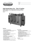
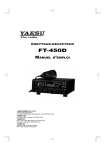
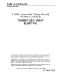
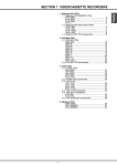
1
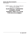
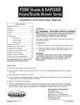
S6161-JB-FSE-010
0910-LP-641-2046
[ SGML Version See Change Record ]
TECHNICAL MANUAL
INSTALLATION, OPERATION &
SERVICE MANUAL
SINGLE OR TWIN
AUTOMATIC
COUNTER MOUNTED
MID LINE COFFEE URNS
DISTRIBUTION STATEMENT E: DISTRIBUTION AUTHORIZED TO DOD COMPONENTS
ONLY; CRITICAL TECHNOLOGY; DATE OF PUBLICATION. OTHER REQUESTS SHALL
BE REFERRED TO THE NAVAL SEA SYSTEMS COMMAND (SEA-09B2).
WARNING: THIS DOCUMENT CONTAINS TECHNICAL DATA WHOSE EXPORT IS
RESTRICTED BY THE ARMS EXPORT CONTROL ACT (TITLE 22. U.S.C. SEC. 2751 ET.
SEQ.) OR EXECUTIVE ORDER 12470. VIOLATIONS OF THESE EXPORT LAWS ARE
SUBJECT TO SEVERE CRIMINAL PENALTIES.
DESTRUCTION NOTICE: DESTROY BY ANY METHOD THAT WILL PREVENT DISCLOSURE OF CONTENTS OR RECONSTRUCTION OF THE DOCUMENT.
PUBLISHED BY DIRECTION OF COMMANDER, NAVAL SEA SYSTEMS COMMAND
JUN 30, 1990
TITLE-1 / (TITLE-2 Blank)@@FIpgtype@@TITLE@@!FIpgtype@@
@@FIpgtype@@TITLE@@!FIpgtype@@
TITLE-2
@@FIpgtype@@BLANK@@!FIpgtype@@
S6161-JB-FSE-010
RECORD OF CHANGES
CHANGE NO.
DATE
TITLE OR BRIEF DESCRIPTION
ENTERED BY
NOTE
THIS TECHNICAL MANUAL (TM) HAS BEEN DEVELOPED FROM AN INTELLIGENT ELECTRONIC
SOURCE KNOWN AS STANDARD GENERALIZED MARKUP LANGUAGE (SGML). THERE IS NO
LOEP. ALL CHANGES, IF APPLICABLE, ARE INCLUDED. THE PAGINATION IN THIS TM WILL NOT
MATCH THE PAGINATION OF THE ORIGINAL PAPER TM; HOWEVER, THE CONTENT IS
EXACTLY THE SAME. ANY CHANGES RECEIVED AFTER RECEIPT OF THIS TM WILL ONLY FIT
IN THIS PAGINATED VERSION.
RECORD OF CHANGES-1 / (RECORD OF CHANGES-2 Blank)
RECORD OF CHANGES-2
@@FIpgtype@@BLANK@@!FIpgtype@@
S6161-JB-FSE-010
TABLE OF CONTENTS
Chapter/Paragraph
Page
GENERAL DESCRIPTION . . . . . . . . . . . . . . . . . . . . . . . . . . . . . . . .
1-5
INSTALLATION . . . . . . . . . . . . . . . . . . . . . . . . . . . . . . . . . . . . . .
1-5
OPERATION START-UP . . . . . . . . . . . . . . . . . . . . . . . . . . . . . . . . .
1-6
HOW TO BREW IN AN AUTOMATIC URN
. . . . . . . . . . . . . . . . . . . . .
1-8
CARE AND CLEANING OF COFFEE URNS . . . . . . . . . . . . . . . . . . . . .
1-9
QUICK SERVICE CHECK OF LIQUID LEVEL CONTROL SYSTEM . . . . . . .
1-22
REPAIR/REPLACEMENT INSTRUCTIONS FOR ELECTRICAL AND
MECHANICAL COMPONENTS . . . . . . . . . . . . . . . . . . . . . . . . . . .
1-23
PART NUMBERS & QUANTITY REQUIRED FOR 1 YEAR
. . . . . . . . . . . .
1-29
. . . . . . . . . . . . . . . . . . . . . . . . . . . . . . . . .
1-39
DIRECTORY . . . . . . . . . . . . . . . . . . . . . . . . . . . . . . . . . . . . . . . .
1-39
VALVE DISASSEMBLY
i
S6161-JB-FSE-010
LIST OF TABLES
Table
ii
Title
Page
Roughing-In Data Parts List . . . . . . . . . . . . . . . . . . . . . . . . . . . . . . . .
1-2
Brew Baslet Selection Chart . . . . . . . . . . . . . . . . . . . . . . . . . . . . . . . .
1-3
PRODUCTION-ENGINEERING DATA . . . . . . . . . . . . . . . . . . . . . . . . .
1-3
Standard Voltage . . . . . . . . . . . . . . . . . . . . . . . . . . . . . . . . . . . . . .
1-4
Standard Voltage (cont’d) . . . . . . . . . . . . . . . . . . . . . . . . . . . . . . . . .
1-4
IV. Trouble Shooting Auto Refill, Low Water Cutoff, and Liquid Level Control
System. . . . . . . . . . . . . . . . . . . . . . . . . . . . . . . . . . . . . . . . . . .
1-17
Part Numbers and Quantities
. . . . . . . . . . . . . . . . . . . . . . . . . . . . . . .
1-30
Manufacturers/Suppliers for Component Parts . . . . . . . . . . . . . . . . . . . . . .
1-39
Recommended Coffee Urn Cleaners
1-40
. . . . . . . . . . . . . . . . . . . . . . . . . . .
S6161-JB-FSE-010
LIST OF ILLUSTRATIONS
Figure
Title
Roughing-In Data
Page
. . . . . . . . . . . . . . . . . . . . . . . . . . . . . . . . . . . . .
1-2
(3)
ROUGH-IN SPECS. FOR AUTO URNS
. . . . . . . . . . . . . . . . . . . . . . . .
1-11
(4)
7400E URN CONTROL CIRCUIT WIRING HARNESS DIAGRAM: NCC TIMER,
AUTO REFILL, LOW WATER CUTOFF, OPT. 43 (AIR AGITATION) . . . . . .
1-13
(5)
TAB TERMINAL HEATER WIRING - URNS WITHOUT PUMP . . . . . . . . . .
1-15
(6)
ILLUSTRATED PARTS BREAKDOWN 7400 SERIES . . . . . . . . . . . . . . . .
1-28
(11)
507028 NCC Timer
. . . . . . . . . . . . . . . . . . . . . . . . . . . . . . . . . . . .
1-33
(12)
505002 Liquid Level Control . . . . . . . . . . . . . . . . . . . . . . . . . . . . . . .
1-33
(13)
521021- Urn Elastomer Kit . . . . . . . . . . . . . . . . . . . . . . . . . . . . . . . .
1-34
(14)
Seal Kit P/N 521028 . . . . . . . . . . . . . . . . . . . . . . . . . . . . . . . . . . . .
1-34
(15)
Option 43 Outside Tube Kit P/N 512015 When Supplied. . . . . . . . . . . . . . . .
1-35
(19)
.5CC Disposable Tube of Loctite 271 Cover Handle Kit for Automatic Urns P/N
513001 . . . . . . . . . . . . . . . . . . . . . . . . . . . . . . . . . . . . . . . . . .
1-36
S301 Standard Open Frame Solenoid Valve . . . . . . . . . . . . . . . . . . . . . . .
1-38
iii / (iv Blank)
iv
@@FIpgtype@@BLANK@@!FIpgtype@@
S6161-JB-FSE-010
CHAPTER 1
SECTION
ELECTRIC, STEAM, GAS
TWIN MODELS:
7443
7446
74410
SINGLE MODELS:
7413
7416
74110
MID LINE AUTOMATIC COFFEE URNS FRESH WATER BREWING SYSTEM THE MID LINE
URN...American’s Budget Cutter, completely automatic coffee urn. When a basic, no trills, nothing added urn is
needed, this is it! Then build by adding what you want - such as air agitation for mixing of coffee, or any other
of the many extras found in the OPTIONS SECTION of this catalog.
AMERICAN STANDARD FEATURES
•FRESH WATER BREWING Special large area heat exchange coil resists scale problems. Heats water for
brewing/sprayover as it travels through coil, fresh for each batch brewed.
•FULLY AUTOMATIC ONE TOUCH BREWING TIMER Most foolproof for operator. No dial or knob to
turn. Concealed setting. Adjust with screwdriver through front panel. Stop sprayover with one touch. Use for
spray rinse of coffee liner.
•AUTOMATIC REFILL OF WATER COMPARTMENT Saves time and attention required to manually fill.
Unlimited supply of hot water for tea, etc. always available.
•ADJUSTABLE BYPASS ON SPRAY ARM
soft or treated water.
Enables proper brew extraction even with variations caused by
•DIAL THERMOMETER WITH MARKED BREW ZONE
•ALL A.I.S.I. TYPE 304
18-8 stainless steel construction.
•ONE ALL STAINLESS STEEL BREW BASKET
•CONTROL BOX ON RIGHT HAND END
of urn at no additional cost.
With 25 filter papers.
If requested, the control box can be located on left hand end
•LOW WATER CUTOFF SYSTEM Solid state probe sensor system provides positive protection against
heater burnout, at start-up or in operation.
•GREATEST SAFETY FOR OPERATOR (OSHA)
All controls operate on 120 Volt.
•SPECIAL PINPOINT CONTROL THERMOSTAT Super sensitive, highest accuracy and reliability, lowest
service cost. Includes marked ″Nite Standby″ position for energy savings.
1-1
S6161-JB-FSE-010
•CLOSED CHAMBER BREWING Brews with NSF approved cover on brew basket. Prevents costly steam/
moisture loss to room. Saves energy with savings of air conditioning load.
•EASY ADJUSTMENT OF SPRAYOVER RATE Simple screwdriver adjustment. No awkward changing of
parts. Improved two stage flow regulator system gives same volume time after time.
•VELVET SMOOTH SPRAY ARM Special teflon coating on spray arm piston prevents liming and insures
smooth operation. Positive ″stops″ on spray arm for operator safety.
•DRAIN IN BOTTOM
•OPTIONS AVAILABLE
Select from Options Section of this catalog.
•DOUBLE SERVICE (SELF SERVICE) FAUCETS
Options Section of this catalog.
Available on both twin and single urns. Choose from
•MILITARY SPECIFICATIONS-MARINE MODIFICATIONS
43263D or latest specification.
Twin and single automatic urns MIL-U-
Available modified for marine (shipboard) use; no spillage of liquid with 15° list in any plane, and other
requirements. Contact factory for detailed quotation and data.
Roughing-In Data
Roughing-In Data Parts List
Model No.
A
7443
7446
74410
7413
30-1/2
34
34
18
1-2
*
B
15-1/4
16-3/4
16-3/4
15-1/4
C
D
7-5/8
8-3/8
8-3/8
7-5/8
7-3/4
8-5/8
8-5/8
5-1/2
+
Work Height
21-5/8
27-5/8
27-5/8
21-5/8
+
Overall Height
27-1/8
33-1/8
34-5/8
27-1/8
S6161-JB-FSE-010
Roughing-In Data Parts List - Continued
*
*
Model No.
A
7416
74110
21
21
B
16-3/4
16-3/4
+
C
D
8-3/8
8-3/8
7-5/8
7-5/8
+
Work Height
Overall Height
27-5/8
27-5/8
33-1/8
34-5/8
Add 2-1/4″ for flue on gas-allow additional 6″ wall clearance.
+
Add 2-1/2″ on gas.
Brew Baslet Selection Chart
Brews
3 Gal.
6 Gal.
10 Gal.
1/2 Batch on 6 Gal.
1/2 Batch on 10
Gal.
Part No.
BB3
BB6
BB810
BB6-3
BB810-6
NOTE
All SS Permanent Filter Brow Basket with SS woven wire cloth bottom is available. Filter paper is available from our stock. See price list.
TWIN MODELS:
SINGLE MODELS:
7443 • 7446 • 74410
7413 • 7416 • 74110
PRODUCTION-ENGINEERING DATA
MODEL NO.
Coffee Capacity Each Liner
*
Gals. Per Hour (Up To)
Electric, Steam
Gas
No. of 5 Oz.
Electric, Steam
Cups Per Hour
Gas
Max. Steam Demand
Lbs. Per Hour
Gas Consumption
BTU Per Hour
*
7443
7446
74410
7413
7416
74110
3 Gal.
25
6 Gal.
30
10 Gal.
42
3 Gal.
15
6 Gal.
18
10 Gal.
20
18
625
24
750
28
1050
9
375
16
450
19
500
450
600
700
225
400
475
50
70
70
30
70
70
35,000
35,000
35,000
18,000
24,000
24,000
Based on spraying over amount of water equal to capacity of liner.
ELECTRIC HEAT Specify electric service desired. Standard is dual voltage 120/240 Volt or 120/208 Volt
single phase 3 wire (neutral wire required). Watts and amps as shown.
1-3
S6161-JB-FSE-010
Standard Voltage
120/240 Volt
1-PH.
KW
8
11.5
15
7
11.5
15
MODEL
7443
7446
74410
7413
7416
74110
120/208 Volt
3 WIRE
AMPS
34
48
63
29
48
63
1-PH.
KW
6
8.5
15
5.5
8.5
15
3 WIRE
AMPS
29
41
72
25
41
72
Standard Voltage (cont’d)
+
MODEL
7443
7446
74410
7413
7416
74110
240 Volt
3-PH.
3 Wire
Specify Opt. 21B
KW
AMPS
10.5
25
12
29
*
15
36
10.5
25
12
29
*
15
36
120/108 Volt
3-PH.
4 Wire
Specify Opt. 21A
KW
AMPS
8
22
11.5
31
*
15
42
8
22
11.5
31
*
15
42
+
480 Volt
3PH.
3 Wire
Specify Opt. 21C
KW
AMPS
12
14
12
14
15
18
12
14
12
14
15
18
+
Control transformer (Option 22) included when no 120 Volt in the field.
*
No extra charge.
STEAM HEAT Specify operating steam pressure. Standard is 10 to 25 PSI Gage. 1/2″ FPT steam inlet and
outlet. Requires plug-in of 3 wire cord to 120 Volt AC outlet. Steam trap to be supplied by others.
GAS HEAT Specify Natural or L.P. gas. Standard includes thermostat with 100% safety pilot shutoff,
stainless steel flue on rear and combustion chamber with aluminum heat shield under gas burner. Requires plug-in
of 3 wire cord to 120 Volt AC outlet. Six and ten gallon models require connection to 160°F hot water line.
OPTIONAL ONE YEAR SERVICE Covers service/labor and parts for one year from date of installation
(maximum of 18 months from date of shipment). See price list.
SECTION
ELECTRIC HEATED MODELS
7443
7446
74410
7413
7416
1-4
S6161-JB-FSE-010
GENERAL DESCRIPTION
This urn is an automatic, pushbutton operated, volume brewing unit. It consists of a non-pressure, vented
water tank of large capacity into which two stainless steel liners are inserted.
Electric heat is used to keep water in the tank always at the desired temperature. For this type of heat, a thermostat, sensing the water temperature and controlling a contactor, switches on and off the electric immersion
heater found inside.
Also in this tank is a heat exchange coil that carries fresh (cold) water up to a top mounted, swivelly attached
sprayarm for discharging a hot water spray over ground coffee during brow. A pushbutton start, electric reset
timer measures the quantity of water sprayed over by timing a constant water flow. The flow of sprayover water
is maintained accurately by a two-stage, adjustable regulator system. Flow through the heat exchange coil starts
and stops as the timer opens and closes a water (brew) solenoid valve. Whenever this brow process is going on
in the urn, an orange pilot light also lights up.
Automatic refill is provided to keep the tank always full of water. Whenever the level drops, a built-in control causes water to enter the tank by opening a second water solenoid valve. This refill valve closes when ″full″
is reached.
Low water cutoff is included to prevent damage to the urn or heater that can be caused by a low water level.
Even at initial start-up, no heat can come on until a safe water level is reached in the tank.
Air agitation, If provided, blends the brewed coffee by allowing low pressure air to bubble up through the
coffee in the coffee liner. Programmed agitation is automatic at the end of each brew cycle. Depressing a manual
agitation switch provides further mixing between brews.
All components of the control system are enclosed in a stainless steel housing on one end of the urn.
INSTALLATION
1. Position urn so that the faucets drip into a drain trough or drain receptacle of some type.
2. Level urn both front to back and left to right. The feet are adjustable for this purpose.
UTILITY CONNECTIONS
Water
1. 3/8″ NPT water inlet located beneath control box.
2. Cold or hot water may be used. Heat input capacity is ample for cold water, and cold water should be used
for best results.
3. Provide shutoff valve and union in supply line near urn.
4. Minimum operating pressure at urn should be 30 PSI.
5. Maximum pressure recommended at urn is 75 PSI.
6. Copper or aluminum tubing should be used for flexibility and avoiding strain on the urn.
7. To insure pressure at the urn of at least 30 PSI, use 3/8″ O.D. tubing for short runs, 1/2″ O.D. tubing for longer
runs, and larger size tubing for unusually long runs.
Electric
1. Field terminal block located inside control box.
1-5
S6161-JB-FSE-010
2. An experienced electrician should be responsible for connecting urn to electric power.
3. Check rating marking on urn to be sure supply lines match voltage and phase requirements.
4. Neutral wire normally required on all single phase and on 208 Volt three phase power supplies to operate 120
Volt AC control Circuit. If single phase, 2 wire service (no neutral) or 3 phase 3 wire service (no neutral), a
transformer is installed to supply 120 volt AC power to control circuit.
5. A fused disconnect switch should be installed near urn.
6. Urn body must be grounded. A grounding conductor terminal is provided for this purpose. Other means of
positively grounding urn may be used.
7. Use only copper wire to connect this urn.
OPERATION START-UP
1. Turn power on to urn. Have spray arm in ″Park″ position, with nozzle in vent tube opening at center rear. Turn
on water supply to urn. With automatic refill, water compartment will fill automatically. Time required to fill
is 10 to 15 minutes. In case of failure to fill, refer to Automatic Refill Service Instruction page.
2. Turn thermostat knob to ″Brew″ position. Pilot light at top of thermostat bezel should light up. Water in urn
should heal up, and rise to high end of ″Brew″ zone on thermometer within approximately 55 minutes,
depending on temperature of water in urn. Pilot light at top of thermostat bezel should go out when water in
urn is at brew temperature. This pilot light will also go out in case of dangerous low water conditions, or no
power at urn due to blown fuses, switch off, or while urn is refilling.
OPERATION START-UP CHECKS
1. Turn thermostat dial to ″Brew″ position. Pilot light at top of thermostat bezel should light up and when thermometer pointer is in high ″Brew″ zone, this pilot light should go out. Water in urn tank is now at brew temperature. NOW and ONLY at initial start-up, we advise checking time of flow of hot water to spray nozzle.
2. Checking Spray-Over Volume and Rate Remove cover from brew basket over one liner. Position spray
nozzle over this brew basket. Liner should be empty and faucet shut off. Push in timer start button and brew
pilot should light up. Hot water should start to spray into brew basket. Allow to spray until brew pilot light
goes out and sprayover stops.
Measure amount sprayed over by drawing off into a calibrated one gallon measure. If amount is more or less
than desired, remove cover to reveal timer adjustment and reset timer using a screwdriver. Longer time-more
sprayover, shorter time-less sprayover. Each 1/4 minute increase or decrease adds or subtracts about 1/3 gallon
to sprayover total. Replace cover after setting.
Note that setting of sprayover bypass valve effects amount of sprayover. Set as desired.
Before actual use of urn, it should be thoroughly cleaned and washed. It is also recommended that a batch
of coffee be brewed in each liner based on a final brewing cycle timer setting, actual muslin bag or filter to be
employed. We recommend that these first batches be thrown out and not used. Strength of brew may be checked
by hydrometer or evaporation tests but flavor test might be poor on first batch.
COFFEE BREWING AND URN BREW CYCLE
Measurement of water quantity sprayed over is by a precision electric timer, controlling an electric solenoid
water valve. When timer is started, water solenoid valve opens, and water line pressure forces fresh water to flow
1-6
S6161-JB-FSE-010
through heat exchange coil and come out of the spray nozzle and spray over the coffee in the brew basket. The
rate at which the water flows is controlled by a two stage water flow regulator system designed to provide accurate flow rate under all conditions.
All urns with coffee liner capacity of 6, 8, or 10 gallons have an adjustable bypass on the spray arm. (Some
3 gallon models may also be so equipped). This bypass allows some spray-over water to bypass the brew basket
and go directly into the coffee liner. By adjusting bypass valve, brew can be controlled for ideal extraction from
coffee.
Variable brewing factors which the coffee urn cannot control are:
1. The uniformity and type of grind on coffee supplied.
2. The uniformity and quality of roasting, and selection of blend and type of coffee beans used, and the freshness of ground coffee used in a brew.
3. Water chemistry - i.e., mineral content, taste factors (chlorine, fluorine, iron, etc.) and effects of any treatment
process occurring ahead of urn.
4. Uniformity and quality of filter paper is also important, and proper storage and handling of paper effects final
brew.
5. Proper and regular, frequent cleaning of all coffee brewing equipment is vital to insure the most delicious tasting brew.
Figure (2)
1-7
S6161-JB-FSE-010
HOW TO BREW IN AN AUTOMATIC URN
1. Place filter in brew basket with designated amount of ground coffee (automatic urns are designed to use 1, 2,
or 3 lbs. of coffee). Make certain you have a level bed of coffee.
2. Replace cover and move spray head over center of coffee grounds.
3. Check thermometer to make certain urn is at brewing temperature. Press start button.
4. When brew cycle is completed (brew light shuts off), remove brew basket and dispose of spent grounds.
5. Mixing of finished brow is accomplished automatically at the end of the brow cycle if the urn has an air agitation option. Where urn is not equipped with air agitation, draw one gallon for each three gallons of finished
brow from coffee faucet, and pour over top into coffee liner.
Coffee ready to serve.
Variable brewing factors which this coffee urn can control are:
1. Contact time of water with ground coffee.
2. Accuracy of water spray-over volume.
3. Temperature of water spray-over.
4. Holding temperature of finished brew.
5. Proper and uniform extraction over coffee brew basket bed area.
6. Proper coffee bed depth in brew basket.
7. Proper and thorough mixing of first rich brew with later, weaker brew for uniform final brew.
Final decision of brewing formula and brewing cycle adjustments rests with the operator and the coffee supplier.
COMPLETE URN BREW CYCLE ADJUSTMENT PROCEDURE
See charts on page following and also Parts Breakdown drawing, following service section of this manual.
Urn must be full of water, and heated to operating range (thermometer pointer at high end of ″Brew″ zone)
before starting adjustment.
1.
Set spray arm bypass valve.
2.
Set timer for 2 minutes.
3.
Remove cover from control housing. Remove cover and brew basket from left liner.
4.
Measure one gallon of water and pour into left liner and mark level on gage shield with pencil. Drain liner.
Close faucet. Swing spray arm over left liner.
5.
Push brew timer start button, and use second hand of watch or stop watch to time spray-over of one gallon
(to pencil line on gage shield). Then drain liner and close faucet.
6.
Check number of seconds required for spray-over of one gallon, approximately 80 seconds recommended.
7.
If spray-over time in seconds is too long, loosen lock nut and screw in adjusting screw (turn clockwise) on
flow regulator inside housing about 1/8 turn. Tighten lock nut. If spray-over time in seconds is too short,
loosen lock nut and screw in adjusting screw out (turn counter clockwise) on flow regulator about 1/8 turn.
Tighten lock nut. Recheck spray-over time as in Step 5.
8.
Now set timer to quantity of water desired.
1-8
S6161-JB-FSE-010
9.
Push brew timer start button and allow to spray-over full timer amount into liner. Check total spray-over
water by drawing off into one gallon measure, a gallon at a time. If spray-over is slightly over or under
desired amount, change timer setting; longer time to increase amount, shorter time to decrease amount
10. Replace cover on control housing and timer cover if applicable. No further adjustment of the flow regulator
should be necessary. Fine adjustments can be made at any time on the timer setting only.
NOTE
This urn has a two stage water flow regulator system. The first stage regulator,
located outside under the control housing is factory set at 25 PSI. Do not change
or adjust this regulator.
The second stage regulator, located inside the control housing is adjustable for
rate and amount of sprayover desired
HALF BATCH BREWING
Standard brew basket is designed for full batch brewing with proper bed depth. Half batch brew will result
in weak final brew, because of thin bed depth, unless half batch brew adaptor is used, or more than normal
amount of coffee is used. Half batch brew baskets are available for 6, 8, and 10 gallon models. They require using
a smaller filter paper size.
Occasional half batches can be brewed in standard full batch brew basket by using slightly more then half of
usual weight of coffee, and using an inverted soup bowl in the center of the brew basket to increase coffee bed
depth around the soup bowl and also reduce bottom filtration area.
CARE AND CLEANING OF COFFEE URNS
1. Always rinse urn immediately after each use.
2. Add small quantity of hot water, brush sides and rinse with hot water until it runs clean. Urn is now ready for
next batch.
3. At end of each day clean and brush urn several times, then rinse thoroughly with hot water.
4. Remove clean-out cap at end of coffee faucet (or take apart faucets which have no caps) and scrub pipe leading to center of urn. Clean urn gage glass with brush and urn cleaner. Rinse!
5. Scrub the faucet, then rinse it thoroughly with hot water.
6. Place a gallon or more of fresh water in urn until next use.
7. Remove cover and clean. Replace cover, and leave partly open.
8. ALWAYS REMEMBER TO EMPTY, AND RINSE THE URN WITH HOT WATER BEFORE USING
AGAIN.
NOTE
On automatic urns, use brew start and stop switches, or the rinse switch, to spray
scalding hot water into liner for cleaning and rinsing. On pourover urns, draw hot
water directly from urn. Make sure urn water tank is kept near full, and heat is
on.
1-9
S6161-JB-FSE-010
SEMI-WEEKLY CLEANING PROCEDURE
1. Be sure outer jacket is full of water.
2. Turn on heat and fill urn liner 3/4 full of water; use only urn cleaning compounds (See Note) following manufacturer’s directions; mix thoroughly and let stand about 30 minutes.
3. Clean gage glasses, faucet pipe, plugs, etc., using long thin brush. Use urn cleaning solution for scrubbing.
Take faucet valve apart and clean thoroughly. Clean all tubes well.
4. Scrub inside of urn and inside of cover with long handled brush. Be sure to clean ″lug nut″ in base of urn
liner.
5. Rinse inside of urn three or four times with hot water-scrubbing each time. Also rinse parts well. Repeat until
all traces of foreign odor and cleaning solution are removed.
6. Leave a gallon or more of fresh water in urn with cover partly open until next use. If cold water is used, allow
urn to cool to prevent cracking liner.
7. Urn baskets may be cleaned by immersing in urn cleaner solution and scrubbing with a stiff brush. Rinse thoroughly and let dry. Sprayheads should be checked to see that all holes are open. If any are clogged, remove
sprayhead and use stiff wire to open.
8. Don’t use soap, scouring powders, or abrasives to clean coffee brewing equipment.
WARNING
Cleaner used can effect taste of coffee if not thoroughly flushed out as covered ABOVE.
NOTE
Coffee system cleaners that have been used successfully:
DIP-IT manufactured by Economics Laboratories, Inc.
4 Corporate Park Drive, White Plains, NY 10604
OXYLITE manufactured by Avril, Inc., Syndet Division
601 N. Third Street, Reading, PA 19601
1-10
S6161-JB-FSE-010
Figure (3) ROUGH-IN SPECS. FOR AUTO URNS
1-11 / (1-12 Blank)
1-12
@@FIpgtype@@BLANK@@!FIpgtype@@
S6161-JB-FSE-010
Figure (4) 7400E URN CONTROL CIRCUIT WIRING HARNESS DIAGRAM: NCC TIMER, AUTO
REFILL, LOW WATER CUTOFF, OPT. 43 (AIR AGITATION)
1-13 / (1-14 Blank)
1-14
@@FIpgtype@@BLANK@@!FIpgtype@@
S6161-JB-FSE-010
Figure (5) TAB TERMINAL HEATER WIRING - URNS WITHOUT PUMP
1-15 / (1-16 Blank)
1-16
@@FIpgtype@@BLANK@@!FIpgtype@@
IV. Trouble Shooting Auto Refill, Low Water Cutoff, and Liquid Level Control System.
PROBLEM
A. Overfilling of water compartment when power to urn is
″OFF″.
B. Overfilling of water compartment only when power to urn is
″ON″
C. Auto refill is erratic in filling.
(Sometimes fills, sometimes
doesn’t)
POSSIBLE CAUSE
1. Fill solenoid valve leaking due
to dirt or scale holding valve
open, or worn plunger seat.
2. Fill solenoid valve installed
backwards.
1. High electrode mated with
scale.
2. Missing or faulty common
connection for electrode circuit.
(COM terminal to urn body.)
3. Liquid level plug-in relay
faulty.
4. Liquid level printed circuit
board faulty.
1. Electrodes shorting to ground
completely or intermittently.
REMEDY
Disassemble and clean out. May require new
plunger assembly. Caution is advised to avoid
damage to valve. See S301 valve instruction
sheet.
Visual.
Install so that port marked ″IN″ is Connected
to outside fresh water supply.
Jumper from HIGH terminal to urn Remove electrode assembly. Clean both elecbody stops fill.
trodes. See note 1
Jumper from COM terminal (next
to HIGH) to urn body stops fill.
Make good, secure connection.
Plug-in relay pushed all the way
onto socket.
Replace liquid level control, if problem continues with relay plugged in all the way.
Replace liquid level control.
Replace electrode assembly. See
1. No power at urn.
Urn fills with electrode wires disconnected from HIGH and LOW
terminals.
Plug-in relay pushed all the way
onto socket. Jumper from NC terminal to adjacent COM terminal
starts fill.
Urn does not fill with electrode
wires disconnected from HIGH and
LOW terminals.
Nothing operates on urn.
2. No water at urn.
No sprayover on automatic urns.
2. Liquid level plug-in relay
faulty.
3. Liquid level control faulty.
D. Auto refill fails to fill water
compartment. (Low water cutoff
failure if heat comes on.)
SERVICE CHECK
Visual
.
Replace liquid level control, if problem continues with relay plugged in all the way and
urn fills only with jumper in place.
Replace liquid level control.
Make sure main switch(es), fuse(s), circuit
breakers) provide power to urn, that fuse* on
urn is OK, and master switch, if provided, is
on. * - or circuit breaker
Make stirs all water supply line valves are
open.
Disassemble and clean out. May require
renewal parts.
Install so that port marked ″IN″ is connected
to outside fresh water supply.
1-17
S6161-JB-FSE-010
3. First stage (outside) regulator
clogged.
4. First stage (outside) regulator
backwards.
note 1
PROBLEM
POSSIBLE CAUSE
SERVICE CHECK
5. Water strainer clogged.
No sprayover on automatic urns.
6. Fill solenoid valve clogged
with scale or frozen closed.
Disassemble.
7. Fill solenoid valve coil inoperative.
Jumper from NC terminal to adjacent COM terminal does not start
fill.
Urn fills with electrode wires disconnected from HIGH and LOW
terminals.
Plug-in relay pushed all the way
onto sock. et. Jumper from NC
terminal to adjacent COM terminal
starts fill.
Urn does not fill with electrode
wires disconnected from HIGH and
LOW terminals.
Jumper from LOW terminal to urn
body during chatter stops it.
8. Electrodes shorting to ground.
9. Liquid level plug-in relay
faulty.
10. Liquid level control faulty.
E. Slow, uneven chattering at end 1. Low electrode coated with
scale.
of fill cycle; settles down; thermostat pilot light switches on and
off in unison with noise. single
phasing See note 2 .
2. High and low electrode wires
reversed on liquid level control.
3. Electrodes not vertical.
4. Liquid level plug-in relay
faulty.
5. Liquid level printed circuit
board faulty.
Visual.
Visual.
REMEDY
Remove and clean micromesh screen filter
located in water strainer. (In line with fill
solenoid valve).
Clean out and/or replace plunger assembly, or
replace entire valve. May require new coil.
Caution is advised to avoid damage to valve.
See S301 valve instruction sheet.
Replace coil. Also check for frozen plunger.
See S301 valve instruction sheet.
Replace electrode assembly. See
note 1
.
Replace liquid level control if problem continues with relay plugged in all the way and
urn fills only with jumper in place.
Replace liquid level control.
Remove electrode assembly. Clean both electrodes. See note 1 .
Red wire should be on HIGH terminal, green
wire on LOW.
Electrode wires should be across from one
another (horizontal) at the electrode assembly
fitting.
Replace liquid level control.
Replace liquid level control.
S6161-JB-FSE-010
1-18
IV. Trouble Shooting Auto Refill, Low Water Cutoff, and Liquid Level Control System. - Continued
IV. Trouble Shooting Auto Refill, Low Water Cutoff, and Liquid Level Control System. - Continued
PROBLEM
POSSIBLE CAUSE
F. High speed (rapid fire) chatter- 1. Capacitor failure on liquid
ing that ends with liquid level
level control printed circuit board
control system failure. See note 2 . causes rapid back and forth
switching between fill and heat.
G. Thermostat set on brew. Water 1. No power at urn.
cold.
2. Power at urn-no power at
heater terminals.
H. Water boils continuously on
brew setting.
3. Voltage at heater terminals but
no heat.
1. Thermostat out of calibration.
2. Thermostat inoperative.
J. Urn circuit breaker trips frequently.
SERVICE CHECK
Visual and audio.
Check main fuse or breaker-check
circuit breaker on urn
Check circuit breaker on urn.
Reset breaker or replace.
Open water supply valve to urn. Clean out
water line strainer.
If none replace thermostat or liquid level system board.
If necessary, replace defective element.
Remove coffee liner to replace.
Thermostat should cut off power to With stat knob set on brew. Pull off knob.
heater when thermometer needle at Turn adjusting screw inside knob shaft clockfar right end in blue brew zone.
wise to reduce cut off setting.
Will not accept calibration (Item 1 Replace thermostat. (Necessary to drain all
above)
water from urn.)
Will not click on or off.
Replace contactor
2. Solenoid valves grounding out. Check coils to ground with
OHmeter.
Dirt or scale on solenoid seat.
Dripping stops with power to urn
off.
Measure water pressure in line to
urn. Check for undersized lines or
other equipment on same supply.
Check 2-3 cycles for accuracy.
Replace entire unit.
Replace coil.
Clean out solenoid valve - replace rubber seat
if necessary.
Turn adjusting screw clockwise to increase
flow - counter-clockwise to decrease.
Increase water pressure to urn. Replace water
lines w/ 3/8″ tube or larger.
Replace timer if erratic.
1-19
S6161-JB-FSE-010
3. Timer repeating.
Replace liquid level control. Also, check
contactor or steam valve or gas valve, fill
solenoid valve, and if provided, control circuit transformer.
Reset breaker or new fuse. Reset urn breaker.
Check water level should be at stop
level on gage.
Check power at thermostat terminals.
Check heater for open element.
3. Contactor sticking in closed
position.
1. Liquid level relay malfunction. Check with OHmeter to ground.
K. Continuous leak from spray
nozzle (slight dripping during
heat up is normal due to expansion drippage).
L. Quantity of water sprayed over 1. Adjust flow regulator inside
erratic.
control box out of adjustment.
2. Line water pressure too low
(under 30 PSI at urn).
REMEDY
PROBLEM
M. Water never reaches brewing
temperature. (High end brew
zone on thermometer.)
N. Water spray over rate slows
shortly after installation of urn.
POSSIBLE CAUSE
Thermostat set too low.
Water supply line strainer
clogged.
SERVICE CHECK
Thermometer needle should stop at
least 1/4″ from high end brew
zone.
Spray over pattern should be full
cone shape
REMEDY
Turn thermostat knob to brew. Remove and
reset adjusting screw in shaft - counterclockwise to increase, cut off temperature.
Remove cleanout cap on ″Y″ strainer on
water supply line in urn. Remove sleeve filter. Clean & replace.
note 1
The electrode assembly is located in the upper portion of the control box. To remove assembly, first remove hex nut from fitting; then, turn
assembly approximately 90° towards front of urn and pull out carefully. Electrode tips can be cleaned with a knife or emery cloth. When replacing, DO NOT OVERTIGHTEN hex nut. Make sure electrodes are vertical; electrode wires should be across from one another (horizontal) at the
fitting.
note 2
Chattering may overwork contactor coil, control circuit transformer, gas valve or steam valve coil, and fill solenoid valve coil. Check that
these components are functioning properly.
S6161-JB-FSE-010
1-20
IV. Trouble Shooting Auto Refill, Low Water Cutoff, and Liquid Level Control System. - Continued
S6161-JB-FSE-010
NOTE
Beginning January, 1979, relay no longer plug-in type, but soldered directly to
liquid level control.
AUTO REFILL AND LOW WATER CUTOFF: WHAT THEY ARE
1. Auto Refill of the water compartment keeps the urn body filled with water. When water is used, the fill valve
opens automatically to let in more. The fill valve closes when the water level reaches full.
2. Low Water Cutoff prevents the electic immersion heater from burning out when there is not enough water to
cover it. When low water occurs, the heat automatically switches off. The heat stays off until more water is
added.
3. A device called a Liquid Level Control keeps the urn filled with water and turns off the heat when the water
level is low.
DESCRIPTION AND OPERATION OF LIQUID LEVEL CONTROL SYSTEM
A. Components
1. Liquid Level Control
change in water level.
- switches power to either the thermostat or the fill solenoid valve by sensing
Figure (7)
2. Electrode Assembly
body.
- consists of a high (short) and a low (long) sensing electrode molded in an epoxy
Figure (8)
3. Urn Body
- provides a common (ground) connection for the electrode circuit.
1-21
S6161-JB-FSE-010
B. Operation
Figure (9)
Figure (10)
QUICK SERVICE CHECK OF LIQUID LEVEL CONTROL SYSTEM
1. All wires secure and property connected.
1-22
S6161-JB-FSE-010
2. Plug-in relay on printed circuit board seated all the way onto socket.*
3. Clean the electrodes. Lime (mineral scale) build-up can interfere with the operation of any liquid level control system.
REPAIR/REPLACEMENT INSTRUCTIONS FOR ELECTRICAL AND MECHANICAL COMPONENTS
Thermostat - Part Number 504001
1.
Shut off electric power and water supply to urn.
2.
Drain water compartment below gland fitting.
3.
Remove access cover from control housing.
4.
Loosen 5/16 hex packing gland from capillary tubing at packing gland fitting at urn body. Remove packing
gland fitting, using 7/8″ wrench. Pull out capillary tubing and thermostat sensing bulb.
5.
Pull off thermostat knob on front of control panel. Remove 2-6/32 bezel screws and push thermostat into
control box. Disconnect wiring from terminals. Remove thermostat.
6.
Install new thermostat; reverse procedure as outlined above. Use thread compound or teflon tape when reinstalling packing gland fitting.
7.
Turn on water and power to urn. Turn thermostat knob to brew position. Urn should fill up to stop mark.
With thermostat knob set at BREW, urn should heat. Adjust thermostat for proper setting.
Seat Cup, Silicone Faucet - Part Number 522102
1.
Empty coffee liner or water compartment through faucet until flow stops. (If water faucet, shut off power to
urn).
2.
Grasp black threaded faucet bonnet nut and turn counter-clockwise until free.
3.
Remove bonnet assembly and clean inside faucet body.
4.
Grasp seat cup and pull off bonnet stem.
5.
Press new seat cup on stem and reassemble.
6.
Hand tighten bonnet nut so faucet does not leak.
Handles, Urn Cover - Part Number 513006 - Figure 19
1.
Remove 10/24 x 1-1/4″ hex head stainless steel bolts-underside of cover.
2.
Remove black metal handle and 2 spacer sleeves.
3.
Position 10/24 x 1-1/4″ hex head stainless steel bolts on cover.
4.
Install spacer sleeves, larger diameter up.
5.
Mount black metal handle atop spacers and tighten bolts.
Spray Arm Assembly - Part Numbers 1214015 and 1214019
1.
Urn must be in ″NO SPRAY OVER″ cycle.
2.
Loosen and remove knurled nut from spray arm inlet chamber at handle end.
*
Beginning January, 1979, relay no longer plug-in type, but soldered directly to liquid level control.
1-23
S6161-JB-FSE-010
3.
Lift complete spray arm assembly off inlet piston.
4.
Replace ″O″ rings and teflon seal (see elastomer kit Part Number 521021 - Figure 12) on inlet piston and
lubricate with silicone grease.
5.
To replace inlet piston, loosen locknut below cam washers and unscrew from hex base fitting.
6.
Install new inlet piston-reversing above procedure-position cam washers as in item 7.
7.
Install new spray arm assembly-hand tighten knurl nut plus 1/8″ turn-position lugs on cam washers to index
spray arm nozzle over spray opening in each urn cover.
Brew Pilot Light - Part Number 515016
1.
Turn off power to urn.
2.
Remove access cover from control housing.
3.
Disconnect wire leads to pilot light.
4.
Remove press nut from pilot light inside of control housing.
5.
Push out pilot light from inside control housing.
6.
Install new light from outside.
7.
Reverse procedure outlined above.
Gage Glasses - Coffee or Water - Part Numbers 522033-034-035 and 522032-049-048
1.
Empty coffee liner or water compartment through faucet until flow stops. (If water compartment, shut off
power to urn).
2.
Remove threaded clean out cap and upper gage glass washer (see Part 521021 elastomer kit - Drawing
A-385-B) from top of gage glass protector tube.
3.
Grasp glass gage through slots in protector tube, pull upward and out.
4.
Install new lower gage glass washer (see Part 521021-elastomer kit-Drawing A-385-B) in bottom of protector tube.
5.
Install new glass tube and new upper gage washer and reassemble.
6.
Tighten cap nut finger tight.
Faucet - Coffee or Water - Part Number 522094
1.
Empty coffee liner or water compartment through faucet until flow stops. (If water faucet, shut off power to
urn).
2.
Loosen union nut connecting faucet to faucet shank.
3.
Remove faucet.
4.
Install new faucet and tighten connecting union nut hand tight plus 1/4 turn.
Electric Heater
1.
Shut off power to urn.
2.
Shut off water supply to urn.
3.
Empty water compartment through faucet and drain valve in bottom. Close drain valve.
4.
Remove left liner, as follows:
1-24
S6161-JB-FSE-010
a.
b.
c.
d.
e.
5.
Place alignment mark on liner ring and urn top.
Remove screws at top, fastening liner ring to urn body (if supplied).
Insert 1/4″ x 1-1/2″ x approximately 15″ long flat bar stock into slot in liner drain nut at bottom.
With wrench applied to bar stock, unscrew drain nut counter clockwise-remove drain nut.
Tap inside of liner near bottom with clenched fist or rubber mallet, to loosen. Lift liner out of urn; save
silicone rubber washer for resealing connection.
Disconnect wiring from heater terminals.
*
IF END MOUNTED HEATER, PROCEED AS FOLLOWS: Figure 17
6.
Using end wrench or socket wrench, remove outside locknut from bulkhead fitting.
7.
Remove all three heating elements through inside of urn.
8.
Install three new heaters from inside of urn. It may be necessary to bend replacement heaters slightly to avoid
interference with heat exchange coil or liner.
9.
Tighten locknut securely.
10. Reconnect wires to terminal and reverse Steps 1 through 4, being sure to place silicone rubber washer
between liner elbow fitting and bottom of liner.
Control Circuit Transformer - Part Number 515043
1.
Shut off power to urn.
2.
Remove access cover from control housing.
3.
Disconnect wiring from transformer.
4.
Remove transformer fastening screws.
5.
Replace transformer; check primary wiring against instructions on transformer for voltage being used.
6.
Reconnect leads per schematic in Technical Manual or on Nameplate.
7.
Replace access cover and turn on power.
Electric Contactor - Figure 18
1.
Shut off power to urn.
2.
Remove access cover from control housing.
3.
Disconnect all power cables and 120 volt coil wiring.
4.
Remove contactor fastening screws; remove contactor.
5.
Install new contactor.
6.
Reconnect 120 volt to coil and power cables to clamp type connections on contactor (all power cable connections to be tightened down securely).
7.
Replace access cover to control housing.
8.
Turn on power to urn.
Solenoid Valve - Brew/Refill Water - Pan Number 505023 - Figure 19
Regulator - Water - Part Number 505021
*
This type heater commences with serial number 972-683.
1-25
S6161-JB-FSE-010
1.
Shut off power to urn.
2.
Shut off water supply to urn.
3.
Remove access cover from control housing.
4.
Disconnect 2 brew/refill water solenoid valves from electric circuit.
5.
Disconnect tube flare nut on water supply at Y strainer.
If slip joint assembly, remove as follows:
6.
Grasp complete water supply assembly in control housing with 2 hands and pull straight out-holding on even
plane-connection into urn at front and rear are slip joint type (no lock nuts).
*
If union flare nut assembly, remove as follows:
7.
Support complete water supply assembly in control housing with one hand and disconnect one flare nut at
each end of assembly.
8.
Disassemble assembly to replace either water regulator Part Number 505021 or water solenoid valves - brew
or refill - entire plumbing 1/4″ NPT.
9.
Reassemble.
10. Install in urn reversing procedure outlined above.
NOTE
If slip joint assembly, replace o-rings (elastomer kit - Part Number 521021) on
male slip fitting and lubricate with silicone grease before installing in urn. Also
line up on horizontal plane before installing to prevent shearing o-rings.
11. Reconnect wiring to solenoid valves - see schematic in Technical Manual or an Nameplate.
12. Turn on power and water supply.
13. Adjust water pressure regulator for proper brew flow per instructions
Electrode Assembly - Part Number 518005 - Figure 16
1.
Shut off power to urn.
2.
Remove access cover from control housing.
3.
Disconnect Red and Green wires from H (high) and L (low) terminals on liquid level control.
4.
Trace Red and Green wire to upper right control housing. Remove 1-1/16 hex electrode packing nut.
5.
Grasp molded composition electrode holder and turn 90° counterclockwise, working gently, remove entire
assembly from urn.
6.
Place identifying mark on top of new electrode holder for vertical positioning in urn.
7.
With electrodes in horizontal position, electrodes pointing towards operator’s side of urn, insert electrode into
urn, line up to vertical position by turning clockwise 90°.
8.
Screw on electrode packing nut, hand tighten only.
9.
Rewire per schematic in Technical Manual or on Nameplate.
10. Replace control housing access cover.
*
This type assembly commences with serial number 972-1429.
1-26
S6161-JB-FSE-010
11. Turn on power.
Timer - Part Number 507028 - Figure 11
1.
Shut off power to urn, and remove access cover from control housing.
2.
Disconnect all wiring from timer.
3.
Remove 2-6/32 screws from timer dial on front panel of control housing.
4.
Push timer into control housing and remove.
5.
Install new timer through inside of control housing.
6.
Position dial plate over timer on front panel control housing, and fasten timer with 2-6/32 screws.
7.
Rewire per schematic in Technical Manual or on Nameplate. Exercise care not to bond terminal tabs on
micro switch; shorts can result.
8.
Replace control housing access cover, and turn on power.
9.
Adjust timer as desired.
Liquid Level Control - Part Number 505002 - Figure 12
1.
Shut off power to urn, and remove access cover from control housing.
2.
Disconnect wiring from all terminals.
3.
Remove and replace entire liquid level control. (Never replace an individual part on above).
4.
Rewire per schematic in Technical Manual or on Nameplate.
5.
Replace control housing access cover and turn on power.
1-27
S6161-JB-FSE-010
Figure (6) ILLUSTRATED PARTS BREAKDOWN 7400 SERIES
1-28
S6161-JB-FSE-010
PART NUMBERS & QUANTITY REQUIRED FOR 1 YEAR
1-29
FIG. &
REF.
3
3
DESCRIPTION
GAGE SHIELDS
522003-Coffee
522002-Water
522004-Coffee
522047-Water
522005-Coffee
522046-Water
GAGE SHIELDS
522033-Coffee
522032-Water
522034-Coffee
522049-Water
522035-Coffee
522048-Water
3
GAGE GLASS
SHIELDS
542050-Upper
542052-Lower
10
SS BAG RINGS
542055-3-4 gal
542011-6 gal
10
MUSLIN CLOTH
FILTERS
542050-3-4 gal
542052-6 gal
2
522094-Faucet-Coffee/Water
2
522102-Faucet Seat
Cup
12
515016-Brew Pilot
Light-5/16
7 31-34 521021 Urn
Elastomer Kit
7413
7413EX
7443
7443EX
1
1
2
1
7444
7444EX
7416
7416EX
7446
7446EX
MANUFACTURER
MFR.
CODE
MFR. PART
NO.
Tomlinson Ind.
87294
87294
87294
87294
87294
87294
A-78-10-1/2
A-78-9-1/2
A-78-13
A-78-12
A-78-15
A-78-14
Tomlinson Ind.
87294
18-6830-80-101/2
18-6830-81-91/2
18-6830-81-13
18-6830-81-12
18-6830-81-15
18-6830-81-14
19-668600
19-666200
2
1
1
1
1
2
1
1
2
1
87294
2
1
2
2
3
3
3
3
1
2
2
10
20
1
1
2
1
87294
87294
87294
87294
2
2
3
3
87294
87294
1
2
20
1
20
1
1
1
10
1
2
3
3
2
3
1
1
1
1
1
1
1
1
1
1
Am. Metal Ware
02594
02594
Gen. Bag Co.
20011
20011
87294
14x9
17x9
Model S
87294
3-S-7
95263
36N2313
Tomlinson Ind.
Leecraft
02594
S6161-JB-FSE-010
1-30
Part Numbers and Quantities
Part Numbers and Quantities - Continued
FIG. &
REF.
9
28
36
11
16
31-34
31-34
21
33
7
7
35
15
31-34
33
513006-Urn Handle
Kit
507028-Timer-NCC
505002-Liquid level
Control
518005-Electrode
Assbly.
504001-Elect. Thermostat
505023-SolenoidBrew/Refill
505010-Wrench for
Solenoid
506001Thermometer-Water
505021-Regulator,
Sprayover
1214015-Spray Arm
Assbly.
1214019-Spray Arm
Assbly.
520001-Silicone
Liner Washer
514005-ContactorPole
515072-Circuit
Breaker-120V
505013-Rep. Kit505023 Solenoid
505026-Rep. Kit505021 Regultr.
Elect/Immersion
Htrs.-End Mntd.
A-668-1-(208V8.5KW-1PH)
7413
7413EX
7443
7443EX
7444
7444EX
7416
7416EX
7446
7446EX
MANUFACTURER
MFR.
CODE
1
1
1
1
1
1
1
1
1
1
1
1
1
1
1
1
1
1
1
1
1
1
1
1
1
1
1
1
1
1
1
1
1
1
1
60219
1
1
1
1
1
02594
1
1
1
1
1
02594
1
1
1
MFR. PART
NO.
02594
National Controls
28081
02594
TAM-1432-120
02594
Robertshaw
Cntrls
ITT Gen. Controls
77857
KX-136-36
60219 S-301PMO2V3BD7
106198E6
02594
1
1
02594
02594
2
4
4
2
4
1
1
1
1
1
1
1
1
1
1
02594
1
2
2
1
2
02594
1
1
1
1
1
02594
Furnas Elect.
23826
02594
2
2
02594
42CE25AF2
1-31
S6161-JB-FSE-010
23
DESCRIPTION
FIG. &
REF.
DESCRIPTION
A-668-2-(208V5.5KW-1PH)
A-668-5-(208V6.0KW-1PH)
A-668-1-(240V11.5KW-1PH)
A-668-2-(240V7.0KW-1PH)
A-668-5-(240V8.0KW-1PH)
A-668-2-(208V8.0KW-3PH)
A-668-4-(208V11.5KW-3PH)
A-668-2-(240V10.5KW-3PH)
A-668-5-(240V12.0KW-3PH)
A-668-7-(480V12.0KW-3PH)
7413
7413EX
7443
7443EX
7444
7444EX
7416
7416EX
7446
7446EX
2
2
02594
2
2
2
3
02594
02594
2
2
02594
3
3
02594
3
3
MFR.
CODE
02594
2
3
MANUFACTURER
3
3
3
3
3
02594
02594
3
3
02594
3
3
02594
MFR. PART
NO.
S6161-JB-FSE-010
1-32
Part Numbers and Quantities - Continued
S6161-JB-FSE-010
Figure (11) 507028 NCC Timer
Figure (12) 505002 Liquid Level Control
1-33
S6161-JB-FSE-010
Figure (13) 521021- Urn Elastomer Kit
Figure (14) Seal Kit P/N 521028
1-34
S6161-JB-FSE-010
Figure (15) Option 43 Outside Tube Kit P/N 512015 When Supplied.
Figure (16)
Figure (17)
1-35
S6161-JB-FSE-010
Figure (18)
Figure (19) .5CC Disposable Tube of Loctite 271 Cover Handle Kit for Automatic Urns P/N 513001
1-36
S6161-JB-FSE-010
SECTION
INSTALLATION AND SERVICE
DESCRIPTION
S301 Standard Open Frame Solenoid Valve is a 2-way, normally closed, direct acting, general purpose type.
All stainless steel construction with optional synthetic seating and sealing materials.
Valves my be mounted in any position. A spring loaded plunger assures positive shutoff. CS4 solenoid coil
is rated at 10 watts.
SPECIFICATIONS
Safe working pressure-psi: See Valve nameplate.
Maximum Flow Media Temp. at 77°F (25°C) ambient Class ″A″ (M) Coil: 185°F (85°C)
On-off cycling-300cpm, max.
Cv FactorPort
Cv
3/64″
1/16″
3/32″
1/8″
5/32″
3/16″
1/4″
3/8″
.05
.10
.21
.36
.44
.65
.85
1.70
INSTALLATION
Check valve specification to make sure of proper application.
CAUTION
This solenoid valve should be installed only by a qualified service person.
1. Clear all lines of foreign matter.
2. Valves are multipoised and may be mounted in any position. Flow must be in direction indicated on valve
body.
CAUTION
Valves with ″W″ in 5th digit position of valve catalog number must be
mounted on a horizontal pipe line with solenoid in an upright position.
1-37
S6161-JB-FSE-010
3. Apply thread seal sparingly to male threads only.
4. Provide clearance for solenoid removal
5. Wire in accordance with applicable national and local codes.
S301 Standard Open Frame Solenoid Valve
SERVICE AND REPAIR
WARNING
Disassembly, reassembly or internal adjustment without factory test may
result in hazardous condition. If control does not operate properly after following the INSTALLATION and SERVICE Instructions, complete control
must be replaced by qualified person.
1-38
S6161-JB-FSE-010
S301 standard solenoid valves provide dependable operation for many years. However, foreign matter
between valve seat and disc can cause leakage.
VALVE DISASSEMBLY
1. Unscrew hex nut from plunger tube to remove lock-washer, nameplate and spring washer.
2. Lift coil frame, coil and bottom spring washer from valve body. Be careful, do not disarrange solenoid assembly.
3. Use ITT/GC wrench No. 63591A to remove solenoid base nut and plunger tube from valve body. Be careful,
do not nick, dent or damage plunger tube or seating surfaces.
4. Slip base nut from plunger tube and check ″O″ ring for damage.
5. Remove plunger assembly and spring from body. Check plunger seating surface for damage and wear.
6. Check square seal ring and valve body seating surface for damage.
7. Reassemble in reverse order.
NOTE
Tighten base nut 18 to 24 inch pounds.
Field replacement parts and instructions are included in available kits. Order these parts kits from Form No.
SDPS30-1.
COIL REPLACEMENT
Turn off electric power to solenoid. Disconnect solenoid leads. It is not necessary to remove valve from pipeline.
Follow steps 1 and 2 under VALVE DISASSEMBLY.
When disassembling solenoid take care to note exact order of placement and quantity of parts. Incorrect reassembly can cause coil burnout. Be careful, do not nick, dent or damage plunger tube.
DIRECTORY
Manufacturers/Suppliers for Component Parts
Mfg. Code
23826
20011
60219
Furnas Electric 6
1000 McKee St.
Batavia, IL 60510
General Bog Co.
3368 W. 137th St.
Cleveland, Ohio 44111
ITT/General Controls
801 Allen Ave.
Glendale, CA 91201
1-39
S6161-JB-FSE-010
Manufacturers/Suppliers for Component Parts - Continued
Mfg. Code
95263
28081
77857
Leecraft
21-37-44th Rd.
Long Island City, NY 11101
National Controls Corp.
9311 N. DuPage Ave.
Lombard, IL 60148
Robertshaw Controls
New Stanton Division
Youngwood, PA
Recommended Coffee Urn Cleaners
″DIP-IT″
″OXYLITE″
1-40
Economics Laboratories Inc.
4 Corporate Park Drive
White Plains, NY 10604
Avril, Inc.
Syndet Division
601 N. Third St.
Reading, PA 19601