1
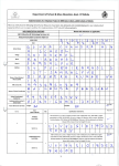
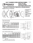
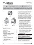
Part Number 471836
Installation Instructions
for RRL/OCI (Resettable/Reusable
Link with Open/Close Indicator)
on FSD, SEFSD, SSFSD series
for RRL/OCI field kit (part numbers
852291 & 822468)
Steps to install an RRL/OCI in a Fire Smoke Damper:
1) Drill/saw a 3 5/8 in. (92mm) diameter hole in sleeve
(Detail 2).
2) Attach indicator bracket to blade. For an airfoil
blade dampers, use existing holes in blade (Detail
1-A). For a 3V blade damper, drill two 0.166
in. (4mm) holes (Detail 1-B). Fasten bracket to
bladewith #10 x 1/2 in. (13mm) TEK screws (or
equilavent).
3) Fit indicator link into blade bracket (Detail 1-C).
4) Insert RRL/OCI unit through hoel in sleeve (round
end inside).
5) Place 4 in. x 4 in. J-box over the flange of the
RRL/OCI unit and align holes.
6) Mount control box to sleeve/sideplate with
#10-16 x 3/4 in. (19mm) TEK screw or equilavent
(Detail 1-D).
7) Place one pushnut on the switch wire. Place
indicator link on switch wire and secure with a
second pushnut (Detail 1-D).
8) Complete wiring and install J-box cover.
RRL/OCI - Exploded View
Detail 1
#10-16 x 3/4 in
.
SIHWH Screw
2 Req’d
D
J-Box Cover
1 Req’d
Upturned Leg Faces
Away From Blade End
#10 x 1/2 in. Tek Screw
or Equivelant
Part No. 415555
2 Req’d
Gasket
1 Req’d
Indicator Bracket
Part No. 658594
1 Req’d
A
Airfoil Blade
Indicator
Link
Push Nuts
2 Req’d
Upturned Leg
Faces Away From
Blade End
#10 x 1/2 in.Tek
Screw
or Equivelant
Part No. 415555
2 Req’d
Indicator Bracket
Part No. 658594
1 Req’d
B
1.625
1.750
0.166 in. dia.
2 Places
C
Indicator
Bracket
Note: Indicator Link Part Nos
.
For Standard Sleeve (short): 457808
For Extended Sleeve (long): 457801
Indicator Link
(short or long; see C)
1 Req’d
3-V Blade
J-Box
1 Req’d
RRL/OCI
1 Req’d
Note: Operator Mounted Upside-Down On Steel Airfoil Units From 10 in. to 17 in. (254mm to 432mm) High
Nominal
Section Height
(in.)
3V
Style
Steel Airfoil
Style
6-7
2.625
2.625
8
3.125
3.125
9
3.625
3.625
10-11
2.625
3.625
12-13
2.625
4.125
14-15
3.125
4.625
16
3.625
5.125
17
4.125
5.625
18
13.125
13.125
19
14.125
14.125
20
14.625
14.625
21
15.625
15.625
22
16.625
16.625
23
17.125
17.125
24
18.125
18.125
25
19.625
19.625
Detail 2
8.375
26
20.625
20.625
27, 39-41
21.625
21.625
28, 42
22.125
22.125
29, 43. 57
23.125
23.125
30, 44, 58
24.125
24.125
31, 45, 55-56,
59
25.125
25.125
32
26.625
26.625
D
INSIDE
SURFACE
< 11" NOM HEIGHT
3.563
>11" NOM HEIGHT
Ø3.625
All dimensions shown in inches.
Wiring Diagram
Resettable Reusable Link/
Open-Closed Indicator
Note: The switch wires wrapped with a
blue marker indicate the closed position
of the damper.
33, 47
27.625
27.625
34, 46
28.625
28.625
35, 49
29.125
29.125
36, 48
30.625
30.625
37, 51
31.125
31.125
38, 50, 52
32.125
32.125
53
23.625
23.625
Yellow
54
24.625
24.625
Yellow
60
4.125
4.125
Electrical Capacity = 10 AMP (max)
Optional Momentary Contact
Test Switch
Orange
NC
Black
Black
NC
P
P = Primary Temperature Sensor
S1
S2
NO
NO
White
Electric Damper
Actuator or Pneu.
Solenoid Valve
Yellow
Yellow
By Others
Damper
Indicator
LIghts
Copyright © 2008 Greenheck Fan Corporation
RRL/OCI Rev 1 July 2008