Transcript
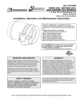
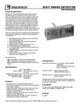
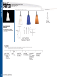
Part number 469419
Firestop Material
INSTALLATION INSTRUCTION SUPPLEMENT
®
Refer to:
‘Installation Instructions for FSD-XXX, DFD-XXX,
SSFSD-XXX & CFSD-XXX Series Fire & Combination Fire
Smoke Dampers’ (Part #461336)
11⁄2
These instructions apply to
hour rated combination
fire smoke dampers and dynamic rated multi-blade
fire dampers mounted in masonry, block, or metal or
wood stud walls. Note: This installation is intended
for underfloor applications where the damper/duct is
directly above (4 in. [101mm] or less) the rated concrete
floor (see Figure 2). No duct impact test was conducted.
Specific requirements in these instructions are mandatory.
These instructions meet the requirements of UL 555.
Installation shall comply with the requirements of NFPA
90A (Standard for the Installation of Air Conditioning and
Ventilating Systems) and UL Classification R13317.
Fire and Combination Fire/Smoke dampers up to a
maximum size of 72 in. W x 96 in. H (1828mm x 2438mm)
may be installed as instructed below.
1. E
xpansion Clearance - Fire damper and sleeve
assemblies expand during periods of intense heat.
Therefore, it is essential that openings in walls or
floors be larger than the fire or fire/smoke damper and
sleeve assembly to allow for this expansion. Minimum
clearances required between the outside of fire or fire/
smoke damper sleeve assemblies and wall openings
are:
• Galvanized steel fire dampers and sleeves: 1⁄8 in.
(3mm) per foot of damper width and height with a
minimum clearance of 1⁄4 in. (6mm), maximum of 1
1⁄2 in. (38mm). Recommended clearances, for width
and/or height dimensions of:
1)48 in. (1219mm) or less: 1⁄2 in. (13mm)
clearance
2) More than 48 in. (1219mm) and 96 in.
(2438mm) or less: 1 in. (25mm) clearance
3) More than 96 in.(2438mm): 11⁄2 in. (38mm)
clearance
• Stainless steel fire/smoke dampers and stainless
steel or galvanized sleeves: 3⁄16 in. (4.7mm) per
foot of damper width and height with a minimum
clearance of 1/4 in. (6mm) , maximum of 2 in.
(51mm)
DFD Series
11/2 Hour Multi-Blade Fire Dampers and
FSD Series
11/2 Hour Combination Fire Smoke
Dampers-Vertical Mount
Recommended clearances, for width and/or height dimensions of:
1) 48 in. (1219mm) or less: 3⁄4 in. (19mm) clearance
2. P
acking (optional) - Polyethylene backer rod, recessed from
surfaces of wall to accommodate the required thickness of
fill material.
3. F
ill Material - Hilti Corporation - FS-One fire stop caulk
applied to a minimum 5/8 in. (16mm) thickness within the
annular space and flush with both surfaces of the wall
with a 1 in. (25mm) overlap onto the gypsum board. If the
damper/sleeve assembly comes into contact with the wall,
a minimum of 3/8 in. (10mm) diameter bead shall be applied
to the interface between the sleeve and contact surface.
Firestop should be installed according to manufacturers
instructions and firestop instructions given in the 2007 UL
Fire Resistance Directory Volume 2B, page 4471.
4. R
etaining Clip - Retaining clip 1 in. x 2 in. x 2 in. x 16 gauge
(25mm x 51mm x 51mm x 1.5mm) is attached to one side of
the wall with 1 1/2 in. (38mm) long #8 sheet metal screws or
masonry screws in the masonry wall. The 1 in. (25mm) leg of
the clip shall be attached to the damper sleeve with 1/2 in.
(13mm) long #10 sheet metal screws. The retaining clips are
required to be spaced a maximum of 6 in. (152mm) from the
top of the sleeve and spaced a maximum of 12 in. (305mm)
on center on the sides of the unit only.
Floor tiles
Rated wall
Fill material
Ductwork
Retaining
clip
max. 4 in. (102mm)
Fill material
(one side only on bottom)
Rated masonry floor
Figure 1
Figure 2
Copyright © 2008 Greenheck Fan Corporation
Firestop Material IOM Rev 2 Mar 2008