1
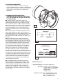
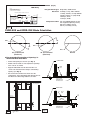
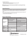
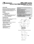
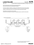
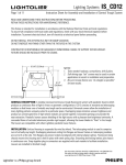
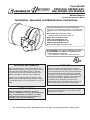
Part #461868
FSDR-XXX, SEFSDR-XXX,
AND SSFSDR-XXX MODELS
1 1⁄2 Hour Fire & Combination Fire
Smoke Dampers
Vertical and Horizontal Mount
Installation, Operation and Maintenance Instructions
FSDR-XXX, SEFSDR-XXX, and SSFSDR-XXX Model
Dampers are intended for installation in accordance with
combination fire smoke damper requirements established
by:
National Fire Protection Association
NFPA Standards 80, 90A, 92A, 92B & 101
BOCA National Building Codes
ICBO Uniform Building Codes
IBC International Building Codes
SBCCI Standard Building Codes
New York City (MEA listing #260-91-M)
“UL CLASSIFIED (see complete marking on product)”
“UL CLASSIFIED to Canadian safety standards (see
complete marking on product)”
UL Standard 555 & 555S (Classification #R13317)
Receiving and Handling
Warranty
Upon receiving dampers, check for both obvious and
hidden damage. If damage is found, record all necessary
information on the bill of lading and file a claim with
the final carrier. Check to be sure that all parts of the
shipment, including accessories, are accounted for.
Greenheck warrants this equipment to be free from
defects in material and workmanship for a period of one
year from the purchase date. Any units or parts which
prove to be defective during the warranty period will
be repaired or replaced at our option. Greenheck shall
not be liable for damages resulting from misapplication
or misuse of its products. Greenheck will not be
responsible for any installation or removal costs.
Greenheck will not be responsible for any service work
or backcharges without prior written authorization.
Dampers must be kept dry and clean. Indoor storage
and protection from dirt, dust and the weather is highly
recommended. Do not store at temperatures in excess of
100°F.
Safety WARNING:
Improper installation, adjustment, alteration,
service or maintenance can cause property damage,
injury or death. Read the installation, operating,
and maintenance instructions thoroughly before
installing or servicing this equipment.
This manual is the property of the owner, and is required
for future maintenance. Please leave it with the owner
when the job is complete.
Due to continuing research, Greenheck reserves the right to change specifications without notice.
Table of Contents
Pre-Installation Guidelines...................................................................................2
Electrical Guidelines.............................................................................................3
Installation.........................................................................................................3-7
•Clearances Required Between Fire Damper Sleeves and Wall/Floor Openings......3
•Sleeve Length and Wall Thickness .................................................................4
•Duct to Sleeve Connections ..........................................................................4
•Securing the Damper Assembly to Wall and Floor Openings..............................4
•Actuator Connections ..................................................................................5
•Connection and Operation of Temperature Control Devices.............................5-6
•FSDR-XXX and DFDR-XXX Blade Orientation....................................................6
•Recommended Preparation of Openings in Wood and Metal Stud Walls...............6
Maintenance.........................................................................................................7
Troubleshooting....................................................................................................7
Pre-Installation Guidelines
The basic intent of a proper installation is to secure the fire smoke or fire damper in the opening in such a manner as to
prevent distortion and disruption of damper operation. This is accomplished by allowing the fire or fire smoke damper in
rated separation openings to expand and for the connecting duct to separate in the event of the collapse of the hanging
system. The following items will aid in completing the damper installation in a timely and effective manner.
1) Check the schedules for proper damper locations within the building. Visually inspect the damper for damage and verify
that the fusible link is in place or has not separated. If fusible link is not present or has separated, replace link. Never
install a fire damper without the proper UL approved fusible link in place. (Fusible link is standard control option. An
electric link may have been provided. Electric links have a button for resetting.)
2) Lift or handle damper using the frame. Do not lift damper using blades or actuators.
3) Do not install screws into the main body area of the damper frame as screws may interfere with and prevent damper
blade from opening and/or closing.
4) Damper has label indicating position of damper assembly in the wall. Install accordingly to comply with manufacturer’s
appropriate UL Classification file number.
5) Damper must be installed into duct or opening free of distortion or other misalignment. Damper must not be squeezed
or stretched into duct or opening. Out of round, racked, twisted or misaligned installations can cause excessive leakage
and/or torque requirements to exceed damper/actuator design.
6) Damper and actuator must be kept clean and protected from dirt, dust and other foreign materials prior to and after
installation. Examples of such foreign materials include but are not limited to:
a)
b)
c)
d)
e)
Mortar dust
Drywall dust
Firesafing materials
Wall texture
Paint overspray
7) Damper should be sufficiently covered as to prevent overspray if wall texturing or spray painting will be performed
within 5 feet of the damper. Excessive dirt or foreign material deposits on damper can cause excessive leakage and/or
torque requirements to exceed damper/actuator design.
8) Caulking is not necessary, nor is it allowed, between the damper sleeve and the wall or floor opening (annular space).
However, caulking may be applied to the retaining plates.
9) ACCESS: Suitable access (such that fusible links, RRL’s, actuators, and linkages can be maintained) must be provided
for damper inspection and servicing. Where it is not possible to achieve sufficient size access, it will be necessary to
install a removable section of duct. (Refer to NFPA 90A).
10)The Code Authority Having Jurisdiction (AHJ) must evaluate and provide approval of final installation where variations to
these instructions are necessary.
Electrical Guidelines
All wiring shall be done in accordance with the National
Electrical Code ANSI/NFPA-70 latest edition, any local codes
that may apply, and wiring diagrams developed in compliance
with the job or project design and specifications.
SAFEty DANGER !
Electrical input may be needed for
this equipment. this work should be
performed by a qualified electrician.
SAFEty CAUtION !
Verify power before wiring actuator. Greenheck is not responsible for any damage to, or failure of
the unit caused by incorrect field wiring.
SAFEty DANGER ! : to avoid causing death or serious bodily harm to building occupants, follow
all instructions carefully. Dampers must close completely to preserve the
integrity of the fire smoke separation.
Installation -
Failure to follow these instructions will void all warranties.
These instructions apply to 11/2 hour rated combination fire smoke and fire dampers mounted (blades must be horizontal) in:
1) masonry, block or stud walls and 2) concrete floors or ceilings. Specific requirements in these instructions are mandatory.
Dampers must be installed in accordance with these instructions to meet the requirements of UL 555 and UL 555S. The
installation of the damper and all duct connections to the damper sleeve shall conform to the latest editions of NFPA 90A,
Standard for the Installation of Air Conditioning and Ventilating Systems, and the SMACNA Fire, Smoke and Radiation
Damper Installation Guide, and UL Classifications R13317.
1. CLEARANCES REQUIRED BEtWEEN FIRE DAMPER SLEEVES AND WALL/FLOOR OPENINGS
Fire damper assemblies expand during periods of intense heat. Therefore, it is essential that openings in walls or floors
be larger than the fire damper assembly to allow for this expansion. The wall/floor opening must be a minimum of 7/8 in.
larger than the outside diameter of the damper. Refer to Section 4 for additional installation considerations.
$-&"3"/$&'03
&91"/4*0/
%6$5
$0//&$5*0/
"3&"
015*0/"-#-"%&104*5*0/
*/%*$"503"/%03&-&$53*$
-*/,
%POPUQMBDFSFUBJOFS
QMBUFJOUIJTHSPPWF
*/
*/
'64*#-&
-*/,
-0$"5*0/
"*3'-08
*/
0QUJPOBM
4FDPOE
3FUBJOJOH
1MBUF
*/
*/."9
%6$5
$0//&$5*0/
"3&"
"$56"503
*/."9
58
4-&&7&-&/(5)
Fig. 1
5017*&80'%".1&3
3
2.SLEEVE LENGTH AND WALL/FLOOR THICKNESS
3.DUCT TO SLEEVE CONNECTIONS
Insert the damper assembly into the prepared opening, to
appropriate depth (see Page 3, Fig. 1).
Dampers are supplied with sleeves and actuators from
the factory and can be installed without the need for
additional field installed sleeves.
Recommended maximum and minimum insertion depth
can be exceeded if:
1) the operation of the damper actuator is not
impeded and
2) the CL of the damper blade remains within the
plane of the wall/floor
important safety dANGER! : To avoid
causing death or serious bodily harm to building
occupants, do not insert screws into the damper
frame unless used for duct connection within 2
in. of the frame end.
The sleeve may extend a maximum of 16 in. beyond the
wall or floor on the actuator side of the damper and a
maximum of 6 in. on the opposite side.
Fig. 2
Gauge of factory furnished sleeve determines the
type of duct to sleeve connections required (see table
below). Any duct connection other than the breakaway
connections are considered rigid.
Type of Duct to
Sleeve Gauge Duct Dimension Sleeve Connection
Permitted
10 ga. (0.138 in.)
14 ga. (0.075 in.)
16 ga. (0.060 in.)24 in. max. dia.
20 ga. (0.036 in.) 24 in. max. dia.
4.SECURING THE DAMPER/SLEEVE ASSEMBLY
TO WALL AND FLOOR OPENINGS
$MBNQJOH
4DSFX
JO.JO5ZQ
'BTUFOFST
/VU
3FUBJOJOH
1MBUF"TTFNCMZ
Damper assemblies must be installed in wall/floor
openings using a single retaining plate on either
side of the wall/floor or by using a retaining plate
on both sides of the wall/floor. The use of a second
retaining plate is allowed, but is not necessary. A
single retaining plate is provided with the dampers. A
second retaining plate can be ordered as an option.
The outside dimension of the supplied retainer plate is
nominal dia. + 4.50”.
• The retaining plate(s) will open up for easy installation when the clamping screw is loosened. If necessary, remove the clamping screw and nut (see Fig. 2).
(IMPORTANT: The clamping mechanism should face away from the wall/floor). Retainer plate(s) are designed to mount flush to the wall/floor and hold the damper in the wall/floor opening.
• Place the damper and attached retainer plate into the wall/floor opening.
• If a second retaining plate is being used, secure it on the opposite side of the wall/floor
DO NOT POSITION RETAINER PLATE(S) IN
FRAME GROOVE
$MBNQJOH4DSFX
Breakaway only
Sleeve thickness must not be less than the gauge of the connecting
duct.
UL Standard 555 requires all ducts to terminate at fire damper
sleeves.
0QFOJOHJO.JO
.JOJNVN8BMM'MPPS0QFOJOH
/PNJOBM%JBJO
Rigid or Breakaway
•Verify position, blade orientation, and actuator
clearance then tighten the retainer plate
clamping screws. The retainer plate(s) must
overlap the wall/floor opening a minimum
of 1 inch. Secure the retainer plate(s) to the
wall using appropriate fasteners (minimum #8
sheet metal screws) at the four corners of each
retainer plate when two retainer plates are used
and also within 3⁄4 in. of the center of each plate
when one retainer plate is used.
5.ACTUATOR CONNECTIONS
Electrical and/or pneumatic connections to damper
actuators should be made in accordance with wiring and
piping diagrams developed in compliance with applicable
codes, ordinances and regulations (see Electrical
Guidelines).
6.CONNECTION AND OPERATION OF
TEMPERATURE RESPONSE DEVICES (Fusible
Link, RRL OPTION, OCI OPTION, TOR OPTION,
and PRV OPTION)
RRL - Dampers will be supplied with a fusible link
temperature response device, as a standard. An optional
thermostat type temperature response device may have
been installed. The device is a RRL (resetable link device),
which only incorporates one thermostat and therefore the
damper remains closed as soon as its sensor temperature
is reached. The RRL does not contain blade indication
switches. Refer to Fig. 4 on page 5 for wiring of the RRL
thermostat.
OCI - The OCI (open or closed indicator) option contains
a single pole, double throw switch used to indicate the
damper blade position. The switch provides a positive open
or closed signal when used in conjunction with remote
indicator lights. Refer to Fig. 5 on page 5 for wiring of the
OCI option.
TOR - The TOR (temperature override device) option
incorporates two thermostats with fixed settings (usually
165°F and 350°F). The primary sensor (the sensor with the
lower temperature setting) can be bypassed by an external
electrical signal allowing the damper to reopen until the
temperature reaches the setting of the secondary sensor
(the sensor with the higher temperature setting). When
the temperature of the secondary sensor is exceeded the
damper closes and remains closed thereafter (Fig. 6)
Fig. 3
ELECTRICAL CAPACITY = 10 AMP @ 120 / 240 VAC
PRV - The PRV (pneumatic relief valve) option is heat
responsive device used with pneumatic actuators. This
can be used in place of EP switch where a RRL is used.
The PRV activates when temperature in excess of the
temperature of the fusible link are detected. When the
fusible link melts, air from the actuator is exhausted to
close the dampers. Pneumatic actuators are to be piped
per local code.
NC
ORANGE
BLACK
L2
BLACK
WHITE/RED
M
P
PRIMARY TEMP
SENSOR
ELECTRIC DAMPER
ACTUATOR OR PNEUMATIC
SOLENOID VALVE
Fig. 4
/05&
5)&48*5$)8*3&483"11&%8*5)
"#-6&."3,&3*/%*$"5&5)&
$-04&%104*5*0/0'5)&%".1&3
&-&$53*$"-$"1"$*5:".1!7"$
The TOR assembly also contains a single pole, double
throw switch used to indicate damper blade position. The
switch provides a positive open or closed signal when used
in conjunction with remote indicator lights. See page 6, Fig.
6 for wiring of the TOR thermostats and indicator switches.
If either the TOR or the RRL is ordered with a pneumatic
actuator, an EP switch is required with an appropriate
electric power circuit to allow the electric thermostat to
control the pneumatic actuator.
RRL Wiring
L1
-
-
OCI Wiring
#:05)&34
:&--08
4
:&--08
4
:&--08
/0
:&--08
%".1&3
*/%*$"503
-*()54
/0
Fig. 5
RATINGS (Fig. 4 & 5)
Integral Switch Type: Single Pole, double throw
Electrical: 10 Amps, 1/3 hp, 120 or 240 Vac
1/2 Amp, 125 Vdc; 1/4 Amp 250 Vdc
5 Amps, 120 Vac “L” (lamp load)
1.0 Amps, 24 Vac
1.5 Amps, 24 Vdc
Temperature Limit: 165° F ( standard primary sensor)
212° F ( optional primary sensor)
250° F ( secondary sensor)
350º F ( secondary sensor)
5&.1&3"563&-*.*5&%07&33*%&
01&/$-04&%*/%*$"503
RATINGS (Fig. 6)
Integral Switch Type: Single Pole, double throw
TOR Wiring
/05&
5)&48*5$)8*3&483"11&%8*5)
"#-6&."3,&3*/%*$"5&5)&
$-04&%104*5*0/0'5)&%".1&3
&-&$53*$"-$"1"$*5:".1!7"$
-
-
#308/
03
0''
03"/(&
0/
/$ #308/
/$
#-"$,
8)*5&
.
)-)*()-*.*54&/403
113*."3:5&.14&/403
0307&33*%&
1
:&--08
4
:&--08
4
)-
#:05)&34
:&--08
/0
&-&$53*$%".1&3
"$56"503031/&640-&/0*%
7"-7&
Electrical: 10 Amps, 1/3 hp, 120 or 240 Vac
1/2 Amp, 125 Vdc; 1/4 Amp 250 Vdc
5 Amps, 120 Vac “L” (lamp load)
1.0 Amps, 24 Vac
1.5 Amps, 24 Vdc
%".1&3
*/%*$"503
-*()54
:&--08
/0
Fig. 6
Temperature Limit: 165° F (standard primary sensor)
212° F (optional primary sensor)
250° F (secondary sensor)
350º F ( secondary sensor)
FSDR-XXX and DFDR-XXX Blade Orientation
30°
Axle
30°
Axle
Axle
30° Off Horizontal
(Maximum)
30° Off Horizontal
(Maximum)
Normal
8.Recommended Preparation of Openings in
Wood and Metal Stud Walls
%".1&3'3".&
• Frame wall openings as shown. (see Fig. 7)
• Double vertical studs are not required for openings
36 in. x 36 in. or smaller.
.&5"-
• Gypsum wall board must be fastened 12 in. on
center to all stud and runner flanges surrounding
opening. (see Fig. 8)
456%
.*/
• All construction and fasteners must meet the
requirements of the appropriate wall design (See UL
Fire Resistance Directory) and/or local codes.
%0/051-"$&
3&5"*/&31-"5&
*/5)*4(3007&
JOPD
.BYJNVN
NFUBMTUVET
JOPD
.BYJNVN
NFUBMTUVET
$FJMJOH3VOOFS
%".1&3'3".&
JO
800%
456%
JOPD
.BYJNVN
.*/
JO
1BOIFBE
4DSFXT
JOPD
.BYJNVN
XPPETUVET
Fig. 8
JO
%0/051-"$&
3&5"*/&31-"5&
JOPD
.BYJNVN
XPPETUVET
*/5)*4(3007&
Fig. 7
'MPPS3VOOFS
9.Round Duct Connections
Round duct connections to shall be attached with #8 sheet metal screws as follows:
• Ducts 22 in. dia. and smaller shall have three screws.
• Ducts larger than 22 in. dia. up to and including 24 in. dia. shall have five screws.
NOTE: All breakaway connections described may have duct sealant, PA2084T duct sealant adhesive manufactured by
Precision, DP1010 water base duct sealant manufactured by Design Polymetrics, or Grey Pookie applied in accordance
with SMACNA recommendations.
Damper Maintenance
Dampers do not typically require maintenance as long as they are kept dry and clean. If cleaning is necessary,
use mild detergents or solvents. If lubrication is desired for components such as axle bearings, jackshaft
bearings and jamb seals, do not use oil-based lubricants or any other lubricants that attract contaminants such
as dust.
Dampers and their electric/pneumatic actuator(s) must be maintained, cycled, and tested in accordance with:
• The latest editions of NFPA 80, 90A, 92A, UL864, and local codes.
• Actuator manufacturer recommendations.
Damper Trouble Shooting
The following is a possible cause and correction list for common concerns with the dampers.
Symptom
Possible Cause
Corrective Action
Frame is out of round causing Adjust frame such that it is round
blades to bind on jamb seals
Actuator linkage loose
Close damper, disconnect power, adjust Damper does not
Defective motor
fully open and/or
Screws in damper linkage
fully close
Actuator linkage hitting wall or floor
and tighten linkage
out to line designated on damper label.
Clean with a non-oil-based solvent
Contaminants on damper
Replace
Locate screws and remove
Damper installed too far into wall. Move
(see Damper Maintenance)
RRL, or TOR sensor
tripped
Heat
Damper does not
operate
No power supplied to the actuator
Actuator runs hot or
makes a humming
noise
Actuator prohibited from reaching
end of stroke
Disconnect linkage from jackshaft,
open damper, power actuator to end of
spring, tighten linkage. Verify amp draw.
Link separated
Heat
Replace link
Push reset button located on backside
of RRL or TOR.
Copyright © 2006 Greenheck Fan Corporation
461868 FSDR-XXX Rev. 7 March 2006