1
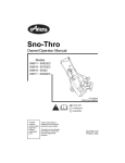
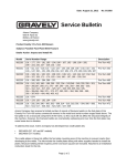
Grass Collection System
with Dump Hopper
200 Series
Owner/Operator & Parts Manual
Model
892031
00466300A 3/07
Printed in USA
TABLE OF CONTENTS
Safety . . . . . . . . . . . . . . . . . . . . . . . . . . . . . . . . . . . . . . 3
Storage . . . . . . . . . . . . . . . . . . . . . . . . . . . . . . . . . . . . 16
Assembly . . . . . . . . . . . . . . . . . . . . . . . . . . . . . . . . . . . 7
Troubleshooting . . . . . . . . . . . . . . . . . . . . . . . . . . . . . 16
Removal . . . . . . . . . . . . . . . . . . . . . . . . . . . . . . . . . . . 14
Specifications. . . . . . . . . . . . . . . . . . . . . . . . . . . . . . . 16
Operation . . . . . . . . . . . . . . . . . . . . . . . . . . . . . . . . . . 14
Parts List . . . . . . . . . . . . . . . . . . . . . . . . . . . . . . . . . . . 17
Maintenance. . . . . . . . . . . . . . . . . . . . . . . . . . . . . . . . 15
Warranty . . . . . . . . . . . . . . . . . . . . . . . . . . . . . . . . . . . 24
INTRODUCTION
THE MANUAL
PRODUCT REGISTRATION
Before operation of unit, carefully and completely read
this Manual and the unit’s Owner/Operator Manual. The
contents will provide you with an understanding of safety
instructions and controls during normal operation and
maintenance.
The Gravely dealer must register the product at the time
of purchase. Registering the product will help the
company process warranty claims or contact you with the
latest service information. All claims meeting
requirements during the limited warranty period will be
honored, whether or not the product registration card is
returned. Keep a proof of purchase if you do not register
your unit.
All reference to left, right, front, or rear are given from
operator sitting in operation position and facing the
direction of forward travel.
Customer Note: If the dealer does not register your
product, please fill out, sign, and return the product
registration card to Gravely.
MODEL AND SERIAL NUMBERS
Transfer
model & serial
number label
from product
registration
here.
When ordering replacement parts or
making service inquiries, know the
Model and Serial numbers of your
unit.
UNAUTHORIZED REPLACEMENT PARTS
Use only Gravely replacement parts. The replacement of
any part on this unit with anything other than a Gravely
authorized replacement part may adversely affect the
performance, durability, and safety of this unit and may
void the warranty. Gravely disclaims liability for any
claims or damages, whether warranty, property damage,
personal injury or death arising out of the use of
unauthorized replacement parts.
Numbers are located on the product
registration form in the unit literature
package. They are printed on a serial
number label, located on the hopper
of your unit.
DELIVERY
Customer Note: If you have purchased this product
without complete assembly and instruction by your
retailer, it is your responsibility to:
Serial Number Label
•
Read and understand all assembly instructions in
this manual. If you do not understand or have
difficulty following the instructions, contact your
nearest Gravely Dealer for assistance.
NOTE: To locate your nearest Gravely Dealer, go to
www.gravely.com on the internet.
WARNING: Improper assembly or adjustments
can cause serious injury.
Figure 1
•
Record Unit Model and Serial numbers here.
Before attempting to operate your unit:
1. Make sure all assembly has been properly
completed.
2. Understand all Safety Precautions provided in the
manuals.
2
DISCLAIMER
3. Review control functions and operation of the unit.
Do not operate the unit unless all controls function
as described in this manual.
Gravely reserves the right to discontinue, change, and
improve its products at any time without notice or
obligation to the purchaser.
4. Review recommended lubrication, maintenance
and adjustments.
The descriptions and specifications contained in this
manual were in effect at printing. Equipment described
within this manual may be optional. Some illustrations
may not be applicable to your unit
5. Review Limited Warranty Policy.
6. Fill out a product registration card and return the
card to the Ariens Company or go to
www.gravely.com.
SAFETY
SAFETY ALERTS
REQUIRED OPERATOR TRAINING
Look for these symbols to point out
important safety precautions. They mean:
Personal Safety Is Involved!
Original purchaser of this unit was instructed by the seller
on safe and proper operation. If unit is to be used by
someone other than original purchaser; loaned, rented or
sold, ALWAYS provide this manual and any needed
safety training before operation.
Become Alert!
SAFETY DECALS AND LOCATIONS
Obey The Message!
ALWAYS replace missing or damaged Safety Decals.
Refer to figure below for Safety Decal locations.
Attention!
The safety alert symbols above and signal words below
are used on decals and in this manual.
2
Read and understand all safety messages.
DANGER: IMMINENTLY HAZARDOUS
SITUATION! If not avoided, WILL RESULT in
death or serious injury.
3
1
WARNING: POTENTIALLY HAZARDOUS
SITUATION! If not avoided, COULD RESULT in
death or serious injury.
10
CAUTION: POTENTIALLY HAZARDOUS
SITUATION! If not avoided, MAY RESULT in
minor or moderate injury. It may also be used to
alert against unsafe practices.
4
11
5
NOTATIONS
9
NOTE: General reference information for proper
operation and maintenance practices.
6
IMPORTANT: Specific procedures or information
required to prevent damage to unit or attachment.
8
PRACTICES AND LAWS
Practice usual and customary safe working precautions,
for the benefit of yourself and others. Understand and
follow all safety messages. Be alert to unsafe conditions
and the possibility of minor, moderate, or serious injury or
death. Learn applicable rules and laws in your area.
Always follow the practices set forth in this manual.
7
3
© Copyright 2007 Ariens Company
Keep hands and body clear of moving parts when
dumping container.
1. DANGER!
To Avoid Serious Injury
Return handle to locked position.
DO NOT operate mower unless guards
are in place or grass pump and entire
bagger are attached.
Use care when tilting unit back to access tractor engine.
Be sure to return handle to locked position.
Use care when turning or backing. Unit protrudes behind
tractor.
OL4840
6. Caution
ALWAYS wear adequate hearing protection.
Keep hands and body clear when dumping
and relatching container.
OL4690
ROTATING FAN! Stop engine and remove
key before clearing.
Wait for all moving parts to stop.
OL0900
7. Operation
Keep children and others away from unit
while operating.
To Dump Grass: Push Handle Out and Lift
OL4140
8. Warning
2. DANGER ROTATING PARTS
Use hearing protection when operating this
equipment.
Avoid Injury
Stay clear of rotating parts.
OL4690
OL3030
9. Important
3. KEEP GUARDS IN PLACE
OL4430
Hoses are subject to normal wear and deterioration.
Check hoses frequently and if they become defective,
install new hoses.
For best collection results, trim hoses so there is no more
than 2 inches excess hose with mower deck lowered.
Do not operate mower unless guards are in
operating position or bagger is attached.
10. Warning
Turn off blower and mower engine before
dismounting or removing and cleaning
screens, hoses, cone or discharge chutes.
OL3320
OL3030
4. WARNING!
Turn off blower and mower engine before
adjusting or repairing the blower unit.
Turn off blower and mower engine before
dismounting or removing and cleaning
screens, hoses, cone or discharge chutes.
OL3030
OL0900
Keep hands and feet clear of moving parts.
Turn off blower and mower engine before
adjusting or repairing the blower unit.
Keep safety shields in place and working.
Keep hands and feet clear of moving parts.
Keep safety shields in place and working.
11. Danger! Hot Surfaces
DO NOT TOUCH parts which are hot from
operation. Always allow parts to cool.
OL0900
5. Operation
OT1281
Disengage PTO (blower) when dumping debris.
To dump grass: Push handle out and lift.
4
SAFETY RULES
Protect eyes, face and head from objects that may be
thrown from unit. Wear appropriate hearing protection.
Read, understand, and follow all safety practices in this
Manual, Owner/Operator Manual, and Engine Manual
before beginning assembly. Failure to follow instructions
could result in personal injury and/or damage to unit.
Avoid sharp edges. Sharp edges can cut. Moving parts
can cut off fingers or a hand.
ALWAYS keep hands and feet away from all rotating
parts during operation. Rotating parts can cut off body
parts.
ALWAYS remove key and wire from spark plugs on unit
before assembly. Unintentional engine start up can cause
death or serious injury.
NEVER place your hands or any part of your body or
clothing inside or near any moving part while unit is
running.
Sharp edges can cut. Movement of parts can cut off
fingers or a hand. Wrap blade(s), wear sturdy gloves and
use extreme caution when working near blades.
ALWAYS disengage attachment, stop unit and engine,
remove key and allow moving parts to stop before
leaving operator’s position.
Installing the blower assembly on your mower requires
the removal of the discharge chute deflector and belt
guard. Retain discharge chute, hinge pin, belt guard and
belt guard hardware in a safe location and reinstall
whenever operating unit without the blower assembly.
DO NOT operate mower unless guards are in place or
blower assembly and entire bagger are attached.
Understand:
Always install counterweights on front axle before
operating unit with bagger attached. Always remove
counterweights from front axle when bagger is removed
from the unit.
• How to operate all controls
• The functions of all controls
• How to STOP in an Emergency
• Braking and steering characteristics
• Turning radius and clearances
DO NOT operate unit with bagger unless front weight is
installed.
Complete a walk around inspection of unit and work area
to understand:
NEVER operate bagger if the unit’s safety interlock
system is not working properly.
Always be aware of maximum sweep of bagger when
turning. Always allow adequate clearance between
bagger, personnel and other objects when turning.
• Work area • Your unit • All safety decals
ALWAYS check overhead and side clearances carefully
before operation. ALWAYS be aware of traffic when
operating along streets or curbs.
As grass catcher fills, be alert to changing unit stability
and control.
Keep children and people away. Keep children out of
work area and under watchful care of a responsible adult.
Disengage PTO when attachment is not in use.
ALWAYS disengage PTO, stop unit and engine, remove
key, engage parking brake and allow moving parts to stop
before leaving operator’s position.
NEVER allow children to operate or play on or near unit.
Be alert and shut off unit if children enter area.
Keep area of operation clear of all toys, pets, and debris.
Thrown objects can cause injury.
DO NOT operate at too fast a rate. DO NOT change
engine governor settings or over-speed engine. Slow
down before turning.
Check for weak spots on docks, ramps or floors. Stay
alert for hidden hazards.
DO NOT mow near dropoffs, ditches or embankments.
The mower could suddenly turn over if a wheel is over
the edge of a cliff or ditch, or if an edge caves in.
Avoid uneven and rough terrain. DO NOT operate near
drop-offs, ditches, or embankments. Unit can suddenly
turn over if a wheel is over the edge of a cliff or ditch, or if
an edge caves in.
DO NOT mow on wet grass. Reduced traction could
cause sliding.
Dust, fog, etc. can reduce vision and cause an accident.
Operate unit only when there is good visibility and light.
DO NOT try to stabilize the machine by putting your foot
on the ground.
Only trained adults may operate unit.
Know the weight of loads. Limit loads to those you can
safely control and the unit can safely handle.
Training includes actual operation.
NEVER operate unit after or during the use of
medication, drugs or alcohol. Safe operation requires
your complete and unimpaired attention at all times.
ALWAYS keep protective structures, guards and panels
in good repair, in place and securely fastened.
DO NOT operate in reverse unless absolutely necessary.
ALWAYS look down and behind before and while
backing.
NEVER allow anyone to operate this unit when their
alertness or coordination is impaired.
Wear adequate safety gear and protective gloves. Wear
proper footwear to improve footing on slippery surfaces.
Watch for holes, ruts, or bumps. Uneven terrain could
overturn the machine.
DO NOT wear loose clothing or jewelry and tie back hair
that may get caught in rotating parts.
5
Grass catcher components are subject to wear, damage
and deterioration, which could expose moving parts or
allow objects to be thrown. Frequently check components
and replace with manufacturer’s recommended parts,
when necessary.
ALWAYS allow adequate clearance for unit, attachments,
operator and objects in work area when turning. Slow
down before turning.
NEVER carry passengers.
If you cannot back up a slope or you feel uneasy on it, do
not mow it.
Mow up and down slopes, not across them.
Keep all movements on the slope slow and gradual. DO
NOT make sudden changes in speed or direction.
Avoid starting or stopping on a slope. If tires lose traction,
disengage the blades and proceed slowly straight down
the slope.
DO NOT operate on slopes over 10°.
DO NOT park on slopes unless absolutely necessary. If
you must park on a slope, always chock or block wheels.
Always set parking brake.
Use a slow speed. Avoid changing speeds on slopes.
Tires may lose traction on slopes even though the brakes
are functioning properly.
Use extra care when loading or unloading unit on trailer
or truck.
Disengage PTO, stop engine, remove key and wait for all
moving parts to stop before servicing, making repairs,
adjusting or when clearing debris.
ALWAYS block wheels. Know all jack stands are strong,
secure and will hold weight of unit during maintenance.
ALWAYS keep protective structures, guards, and panels
in good repair, in place and securely fastened. NEVER
modify or remove safety devices.
Keep unit free of grass, leaves, or other debris. Clean up
oil or fuel spills.
Check bags and bagger parts prior to each use for any
holes, abrasions, mildew, or structural damage. Replace
parts when necessary.
Keep all hardware properly tightened.
Maintain or replace safety and instruction labels, as
necessary.
Keep unit free of debris. Clean up oil or fuel spills.
DO NOT store bags with grass in them.
DO NOT use double blade kits while bagging.
For extended storage, clean unit thoroughly. See Engine
Manual for proper storage.
ALWAYS lower cutting mower deck when unit is parked
or stored.
Use only attachments or accessories designed for your
unit and properly installed.
Check attachment components frequently. If worn or
damaged, replace with manufacturer’s recommended
parts.
6
ASSEMBLY
Item
Description
Qty Part Number
23 Bolt 5/16-18 x 4-1/2
2 06228300
24 3/8-16 x 3 Hex Bolt
6 05957800
25 23/64 / 3/8 x 3-1/4 Clevis Pin
2 02747500
26 3/8-16 x 1/2 Tapping Screw
4 07412900
27 3/8-16 x 2 Hex Bolt
1 05963300
28 3/8-16 Flange Nuts
2 06534900
29 Ball Joint
1 00192400
30 Latch Rod
1 00192300
31 5/16-24 Hex Nut
1 06529500
32 5/16 Lock Washer
1 06308600
33 Rue Ring Cotter Pin
4 06715100
34 3/4-10 1-1/2 Hex Bolt
2 05959600
35 3/4-10 Nylon Lock Nut
2 06540800
36 1/2-13 x 1 Hex Bolt
2 05947100
37 Pivot Frame Handle
2 00615703
38 14 x 3/4 Panhead Screw
4 Not Available
39 Left Frame Leg
1 00615701
40 Right Frame Leg
1 00615702
41 Main Frame
1 00197800
42 Spring
1 08354400
43 5/8 x 3 Detent Pin
2 00673600
44 5/8 Washers
2 06442800
45 5/32 x 2-5/8 Hair Pin Clips
2 06715000
46 Link Pin
2 00194100
47 52"/60" Blower Baffle - Rear
1 00887651
48 72" Blower Baffle - Rear
1 00945151
NOTE: A front blower baffle is not required for 72-inch
Mower Decks.
WARNING: AVOID INJURY. Read and
understand the entire Safety section before
proceeding.
TOOLS REQUIRED
•
Wrenches: 7/16", 1/2", 9/16"
•
Drill
•
13/32" Drill bit
•
Utility Knife
UNPACKING UNIT
IMPORTANT: Remove contents from carton carefully.
Place painted parts on a flat piece of cardboard to avoid
scratching them. Please note there will be two hardware
packages, one shipped inside the grass collector and the
other with the blower assembly.
Package Contents:
Check the contents of your kit for the parts listed in
figure 2:
Item
1
2
3
4
5
6
7
8
9
10
11
12
13
Description
Collector Assembly
Collector Inlet
Tool-Less Hose Clamp
Hose
Counterweight
60" Blower Baffle - Front
52" Blower Baffle - Front
Weight Plate
Rubber Bumper
5/16" Wing Knob
5/16" Wing Knob
Hair Pin
V-belt - 72-Inch Mower Deck
V-belt - 52-Inch Mower Deck
V-belt - 60-Inch Mower Deck
14
15
16
Lift Handle
Blower Assembly
Finger Guard
52-Inch
17
18
60-, & 72-Inch Finger Guard
13/32 x 1-1/2 x 1/4 Flat
Washer
3/8-16 Nyloc Nut
1/4-20 Locking Nut
1/4-20 x 1/2 Hex Bolt
5/16 x 47/64 x 1/16 Flat
Washer
19
20
21
22
Qty
1
1
1
1
4
1
1
1
2
2
3
2
1
1
Part Number
00615700
00192000
02770200
00486100
01542200
00469651
00469551
00451851
07533600
07531700
07500008
06701000
07239700
07236200
1
1
1
07213200
00615703
69244000
1
1
2
00483851
00491851
06400006
6
2
2
2
06545500
06543500
05947900
06435800
7
1
2
48
47
3
4
41
6
5
15
16
7
17
37
14
8
40
10
13
30
12
39
9
11
ODD0182
MOUNTING HARDWARE
19
18
21
20
22
23
24
46
44
25
45
26
43
38
27
42
36
28
35
ODd0436
34
33
32
29
31
Figure 2
8
INSTALLATION
14
Adjust the Parking Brake
27
NOTE: The additional weight of the grass container
requires a parking brake re-adjustment.
42
33
1. Remove the rear wheels.
2. Set the spring length and return gap as shown
below.
28
28
1/16-in. (1.59 mm)
1-1/4-in.
(3.18 cm)
30
29
31, 32
Item
OF3303
Assemble the Grass Container
Description
14
Lift Handle
31
5/16-24 Hex Nut
27
3/8-16 x 2 Hex
Bolt
32
5/16 Lock
Washer
28
3/8-16 Flange
Nuts
33
Rue Ring Cotter
Pin
29
Ball Joint
42
Spring
30
Latch Rod
Figure 3
3. Replace the rear wheels. Tighten the lug nuts to
51–72 lb-ft (69–97 N•m).
Item
Description
Figure 4
Figure 4
NOTE: Use three or more people to install the collector
box on the main frame. The weight and bulk of the grass
collector make it difficult to install safely without
assistants.
Install the Mounting Frame and Grass Container
Figure 5
1. Remove the hardware holding the rear bumper to
the unit frame and then install the left lower frame
leg on the frame with three 3/8-16 x 3 hex bolts
(item 24) and 3/8 lock nuts (item 19). Repeat for the
right lower frame leg.
1. Slide the lift handle (item 14) into the slot of the
handle mount bracket on the collector box.
NOTE: You may need to remove the grip on the lift
handle to fit the handle through the slot.
2. Connect the extension spring to the open hole in
the handle mount bracket and then to the lift handle
(item 14).
NOTE: Do not remove the bumper from the unit.
2. Install the main frame on the lower frame legs with
two 3/4-10 x 1-1/2 hex bolts (item 34) and two
3/4-10 nylon lock nuts (item 35) and with two
1/2-13 x 1 hex bolts (item 36) and two pivot frame
handles (item 37).
3. Connect the lift handle to the grass container with
one 3/8-16 x 2 hex bolt (item 27) and two 3/8-16
flange nuts (item 28).
4. Install the ball joint on the latch rod about half way
down the threads on the latch rod so some thread is
available for adjustment.
3. Have two people hold the grass container in
position while a third person connects the container
to the main frame with two detent pins (item 43),
two 5/8 flat washers (item 44) and two 5/32 x 2-5/8
hair clips (item 45).
5. Connect the ball joint (item 29) to the latch hook on
the grass container with one 5/16-24 hex nut
(item 31) and one 5/16 lock washer (item 32).
6. Connect the latch rod to the lift handle with a
3/32 x 3/4 cotter pin (item 33).
9
NOTE: Two people should install the grass inlet. Install
the grass inlet from the inside of the grass container and
point the inlet down to the ground. Then, while one
person aligns the mounting clamps with the holes in the
side of the aluminum container, the other person tightens
the machine screws.
33, 46
Mounting
Clamps
2
43, 44, 45
41
36, 37
39
24
34, 35
33
Door Opening
Linkage
Rear Bumper
Figure 6
19, 24
INSTALL COUNTERWEIGHTS
Item
Description
Item
Description
19
3/8-16 Nyloc
Nut
37
Pivot Frame
Handle
24
3/8-16 x 3 Hex
Bolt
39
Left Frame
Leg
34
3/4-10 1-1/2
Hex Bolt
41
Main Frame
43
5/8 x 3 Detent
Pin
44
5/8 Washers
35
36
3/4-10 Nylon
Lock Nut
1/2-13 x 1 Hex
45
Bolt
Figure 5
CAUTION: Always install counterweights on
front axle before operating unit with bagger
attached. Always remove counterweights from
front axle when bagger is removed from the unit.
1. Install the weight plate on the front axle with two
clevis pins (item 25) and hair pins (item 12).
2. Install the four counterweights on the bracket and
secure with two 5/16-18 x 4-1/2 carriage bolts
(item 23) and two wing knobs (item 10).
5/32 x 2-5/8
Hair Pin Clips
4. Connect the left and right door opening linkages to
the main frame with one Rue-Ring cotter pin
(item 33) per side.
5. Test the function of the dump mechanism by pulling
the lift handle away from the grass container and
then lifting upward. The container should pivot
backwards toward the ground and the door should
open.
6. Install the collector inlet (item 2) on the grass
container with four mounting clamps and four
14 x 3/4 panhead screws (item 24).
10
5
23
Front Blower
Baffle (item 6
or 7)
18
Footrest
12
10
Mower Deck
52-Inch
60-Inch
72-Inch
8
25
Baffle Measurements
5-3/4 Inches
2-7/8 Inches
No Baffle Required
Figure 8
3. Remove the blower cover.
4. Choose the appropriate finger guard according to
the mower deck size:
Item Description
5
Counterweight*
12
Hair Pin
8
Weight Plate
23
Bolt 5/16-18 x 4-1/2
10
5/16" Wing Knob
25
23/64 / 3/8 x 3-1/4
Clevis Pin
52-inch mower decks use part number 00483851 (1
notch, 8" long).
•
60 & 72-inch mower decks use part number
00491851 (3 notches, 5.50" long).
5. Install the finger guard with two 1/4-20 x 1/2 hex
bolts (item 21) and top-locking flange nuts
(item 20). Install the bolts so the nuts are inside the
blower.
ODd0326
Item Description
•
6. Replace the cover. Make sure the safety decals
face outside where operators and bystanders can
see them.
Install Rear Baffle
Figure 7
1. Choose the appropriate baffle according to the
mower deck size as shown in figure 9.
Install Front Baffle and Finger Guard on Blower
Assembly (Figure 10)
52"/60" Mower
Deck Baffle
1. Remove one mounting bolt from the idler release
lever.
72" Mower
Deck Baffle
2. Choose the appropriate blower baffle according to
the table below (Figure 8) and then install the
blower baffle (item 6 or 7) with two 3/8-16 x 1/2
tapping screws (item 26).
48
47
Figure 9
2. Install baffle to blower assembly as shown in
figure 10.
11
15
Idler Disengage
Blower Cover
and Hardware
26
Detent
Pin
15
13
20
Bend tab down
as needed to
obtain a snug fit
onto mower
deck assembly.
6, 7
ODd0234
26
16
Ppt0090
47, 48
21
Item
Description
15
Blower Assembly 16
Finger Guard
6, 7
Front Baffle (not
needed on 72"
decks)
21
1/4-20 x 1/2 Hex
Bolt
1/4-20 Locking
Nut
26
20
Item
Item Description
Item Description
13
15
V-Belt
Blower Assembly
Figure 11
Description
4. Connect the drive belt to the deck pulley.
Blower
Assembly
Pulleys
3/8-16 x 1/2
Tapping Screw
Compression
Spring and
Washers
V-Belt
47, 48 Rear Baffle
Figure 10
Double
Pulley
Install Blower Assembly on Deck
1. Remove discharge chute and right belt cover from
the deck.
2. Install the drive belt on the blower assembly.
NOTE: The bagger kit includes three V-belts that have a
part number printed on each V-belt. Select the
appropriate belt for your deck:
•
52-inch mower deck V-belt (part number 07236200)
•
60-inch mower deck V-belt (part number
07213200).
•
72-inch mower deck V-belt (part number 07239700)
OTt3024
Figure 12
NOTE: To increase belt tension add washers to the
compression spring. Decrease tension by removing
washers. Four washers for 52", two washers for 60" and
72" decks (figure 13).
3. Install the blower assembly on the deck and secure
with the detent pin. Make sure the detent pin
passes through the bracket on the mower deck.
12
INSTALL HOSE (FIGURE 15)
4 Washers for
52-inch decks
Connect the Discharge Hose
1. Trim the hose to the required length.
For 52-inch and 60-inch Decks, trim the hose so the
hose does not pull tight when the grass container is
in the dump position and the deck is set to its lowest
cutting height.
For 72-inch decks no trimming is required.
2 Washers for 60& 72-inch decks
2. Connect the hose to the blower assembly and then
to the collector inlet. Secure the hose to the
collector inlet with the hose clamp.
Figure 13
3. Adjust the collector inlet angle to remove any sharp
bends or kinking.
5. Replace the belt cover removed in step 1. Keep the
discharge chute for operating the machine without
the blower attached.
CAUTION: Deflected material may cause injury.
ALWAYS operate mower with bagger cover
closed and secured, blower assembly fastened
securely, or with chute deflector in operating
position.
NOTE: If you prefer tool-less belt removal, replace the
belt cover with the hardware provided in this kit. See
Figure 14.
52-Inch Decks
Rubber
Bumper
(Item 9)
5/16" Wing
Knob
(Item 11)
2
Belt Cover
15
4
Rubber
Bumper
(Item 9)
60-Inch Decks
3
5/16" Wing
Knob
(Item 11)
Belt Cover
Item Description
Item Description
2
Collector Inlet
4
Hose
3
Tool-Less Hose
Clamp
15
Blower Assembly
Figure 15
72-Inch Decks
5/16" Wing
Knob
(Item 11)
Belt Cover
Figure 14
13
REMOVAL
REMOVING BAGGER KIT
CAUTION: Deflected material may cause injury.
ALWAYS operate mower with bagger cover
closed and secured, blower assembly fastened
securely, or with chute deflector in operating
position.
1. Remove the hose from the blower assembly and
collector inlet (see figure 15 on page 13).
2. Remove belt cover.
3. Remove V-belt from double pulley (see figure 12 on
page 12).
4. Remove blower assembly (see figure 11 on
page 12).
CAUTION: Always install counterweights on
front axle before operating unit with bagger
attached. Always remove counterweights from
front axle when bagger is removed from the unit.
5. Re-install belt cover.
6. Install discharge chute.
7. Remove counterweights (see figure 7 on page 11).
8. Remove grass container, mounting frame and
mounting legs (see figure 5 on page 10).
OPERATION
EMPTYING THE GRASS CONTAINER
WARNING: AVOID INJURY. Read and
understand the entire Safety section before
proceeding.
If container stops picking up grass clippings, container
may be full.
To empty container:
BEFORE EACH USE
1. Park the unit where you want to empty the
container.
1. Check bagger parts for wear, deterioration or
damage. Replace ONLY with Gravely original
service parts before operating.
2. Disengage PTO, stop engine and remove ignition
key. Wait for all moving parts to stop before leaving
operator’s position.
2. Make sure counterweights are installed.
3. Pull the lift handle away from the grass container
and then lift upward. The container should pivot
backwards toward the ground and the door should
open, releasing container contents.
3. Make sure all hardware is tight.
IMPORTANT: Check tool-less hardware often. Tighten as
needed.
4. Remove any grass buildup from bagger parts.
4. Clean out hose.
5. Ensure hose is fastened securely on upper boot
and blower assembly.
5. Pull the lift handle back and down to pivot the
container upright and to close the door.
BAGGING
6. Push the lift handle in towards the container to lock
the door latch in place.
Starting
IMPORTANT: Make sure the container door latches
securely.
1. Start engine and engage PTO according to unit
owner’s manual.
2. Set throttle to full.
UNCLOGGING GRASS CONTAINER
3. Choose a slow ground speed.
WARNING: MOVING PARTS can cut or
amputate body parts.
Shut Off
1. Disengage PTO.
NEVER attempt to clear blower assembly while
engine is running.
2. Shut off unit according to unit Owner/Operator’s
manual.
ALWAYS stop engine, remove key, and wait for
moving parts to stop.
WARNING: Lower attachment, stop engine, and
remove key to prevent unauthorized use. DO
NOT park on slopes.
Sharp edges can cut. Movement of parts can
cut off fingers or a hand. Wrap blade(s), wear
sturdy gloves and use extreme caution when
working near blades or impeller.
14
5. Reinstall hose.
WARNING: PINCH POINT! Use extreme
caution when unclogging blower assembly.
Impeller can cut or pinch your hand, even when
not in operation. Wear sturdy gloves when
working near impeller.
NOTE: Perform steps 6 and 7 if clog is in blower
assembly.
WARNING: Blades rotate when impeller rotates.
Impeller rotates when blades rotate. Block
blades to prevent rotation before proceeding.
If hose or blower assembly gets clogged, stop forward
motion and allow unit to clear itself. If unit will not clear
itself, unclog the hose and/or blower assembly manually
as instructed below.
6. Clear grass from blower assembly.
7. Reinstall hose and tighten hose clamp.
1. Stop engine and remove ignition key. Wait for all
moving parts to stop.
OPERATING TIPS
2. Remove hose from inlet on grass container.
(figure 15).
•
Cut grass when it is dry.
•
Cut grass in two passes when cutting thick, long, or
wet grass. Make the first cut higher than desired.
Make the second cut at desired height.
•
Always use full throttle when bagging.
3. Remove hose from blower assembly.
NOTE: Perform steps 4 and 5 if clog is in the hose:
4. Remove clogged grass.
MAINTENANCE
Check V-Belt
Gravely Dealers will provide any service or adjustments
which may be required to keep your unit operating at
peak efficiency.
Check V-belt tension after initial first two hours of use and
every 10 hours thereafter. Check V-belt for wear every 10
hours; replace V-belt if worn or deteriorated (see
Replacing V-Belt (Figure 16) on page 15).
WARNING: AVOID INJURY. Read and
understand the entire Safety section before
proceeding.
REPLACING V-BELT (FIGURE 16)
1. Remove belt cover.
MAINTENANCE SCHEDULE
2. Remove blower assembly from mower deck.
The chart below shows the recommended maintenance
schedule that should be performed on a regular basis.
3. Remove old V-belt.
4. Install new V-belt on blower assembly pulley.
5. Install blower assembly to mower deck.
MAINTENANCE SCHEDULE
Service Performed
Each Use
Check Fasteners
•
Inspect Bagger Parts
•
Clean Unit
•
Check V-belt
6. Route new V-belt onto double pulley (see Install
Blower Assembly on Deck on page 12).
Every 10 hrs.
Blower
Assembly
Pulleys
Double
Pulley
•*
* Check V-belt tension after initial first two hours of use.
Check Fasteners
V-Belt
IMPORTANT: Be certain that all hardware is tight before
each use. Pay special attention to the guards and safety
shields. Check tool-less hardware often. Tighten as
needed.
ODd0372
Inspect Bagger Parts
Before each use, inspect bagger parts for any holes,
abrasions, or structural damage. Replace any worn or
damaged parts.
Figure 16
Clean Unit
Clear away grass build-up in bagger before and after
each use.
15
STORAGE
Clean plastic surfaces with sponge and mild detergent.
Dry with a soft cloth.
WARNING: AVOID INJURY. Read and
understand the entire Safety section before
proceeding.
Remove all debris from mesh bags before storing.
Remove all dirt, grease, leaves, etc. from unit.
IMPORTANT: NEVER spray unit with high-pressure
water. DO NOT store unit outdoors.
Store in a clean, dry area.
Ensure all fasteners are properly tightened. Inspect
moving parts for damage and wear.
Touch up all rusted or chipped painted surfaces.
TROUBLESHOOTING
PROBLEM
PROBABLE CAUSE
Collector fails to pickup
grass or leaves.
Blower Assembly stops
or slows.
CORRECTION
1. The dump hopper is full.
1. Shut off engine, remove key, and empty
hopper.
2. Grass container is clogged.
2. See Unclogging Grass Container on
page 14.
1. Worn or damaged V-belt.
1. See Replacing V-Belt (Figure 16) on
page 15.
SPECIFICATIONS
Model Number
Description
Added Length to Unit
Bagger Capacity
Added Width to Mower
Deck
89203100
200 Series Bagger
27"
12 Cu. Feet
12 inches
16
PARTS LIST
DECALS
11
8
5
9
6
1
13
10
7
12
2
3
07742300B
4
052255
Item Part No.
1
2
3
4
5
6
7
8
9
10
11
12
13
07735200
07742300
08088200
05225500
05360200
05360600
05360300
05360800
05361000
05360500
05360400
05360700
05360900
Qty.
2
1
1
1
1
1
1
1
1
1
1
1
2
Description
Decal, Danger
Decal, Warning
Decal-Caution, Grass Pump
Decal, Gravely
Decal, Warning
Decal, Important
Decal, Hearing Warning
Decal, Hot Surface Warning
Decal, Operation
Decal, Pinch Point Caution
Decal, Rotating Parts Warning
Decal, Lift Handle Instruction
Decal, Reflective
17
COUNTERWEIGHTS
2
1
4
7
3
5
6
ODd0326
Item Part No.
1
2
3
4
5
6
7
06228300
01542200
07531700
06400006
02747500
00451851
06701000
Qty.
1
4
2
2
2
1
2
Description
Bolt .312-18 x 4.5
Counterweight
Knob, Wing .312-18 UNC (Tool-less hardware option)
Washer, Flat Steel .406 x 1.50 x .245
Pin-Clevis .368/.373 x 3.25
Weldment, Weight Plate
Hair Pin
18
––– NOTES –––
19
GRASS CONTAINER ASSEMBLY
30
29
4
6
28
27
7
8
26
31
25
5
9
24
23
10
22
21
20
19
18
11
13
17
16
15
14
12
1
32
33
34
35
2
3
38
37
40
36
20
39
GRASS CONTAINER ASSEMBLY
Item Part No.
1
2
3
4
5
6
7
8
9
10
11
12
13
14
15
16
17
18
19
20
21
22
23
24
25
26
27
28
29
30
31
32
33
34
35
36
37
38
39
40
00197800
00615701
00615702
00193700
00193500
00193600
00194000
00193400
00193000
00193300
00192900
00192800
00194100
00192700
00192600
00193100
00192500
00193200
00192400
07068800
00192300
06545600
00192200
08354400
07538700
00192100
00192000
00191900
00193800
00193900
06715100
05959600
06540800
06545500
05957800
05947100
00615703
00673600
06442800
06715000
Qty.
1
1
1
1
1
1
1
1
1
1
1
2
2
1
1
1
1
1
1
2
1
2
2
1
1
1
1
4
1
4
2
2
6
6
2
2
2
2
2
Description
Frame, Top Main
Frame, Main Left Leg
Frame, Main Right Leg
Screen Support
Handle Mount
Box Back and Sides
Fill Gauge
Box Door/Frame
Plastic Door
Upper Door Member
Door Frame Assembly
Pivot Bracket
Linkage Pin
Base Frame Pivot Mount
Latch Hook Plate
Base Frame
Latch Hook
Box Bottom
Ball Joint
Adjusting Screw
Latch Rod
Nut, Adjusting
Rod, Linkage
Spring, Latch
Grip, Handle
Handle, Box
Inlet
Clamp, Inlet
Screen
Box Top, Aluminum
Rue-Lock Pins
Bolt, Hex .75-10 x 1.50 Grade
Nut, Lock .75-10
Nut, Nylon Lock .375-16
Bolt, Hex .375-16 x 3.0 Grade 5
Bolt, Hex .50-13 x 1 Grade 5
Handle, Pivot Frame
Pin, Detent .625 x 3.00
Washer Flat Steel .656 x 1.31 .095
Pin, Hair .156 x 2.625
21
BLOWER HOUSING ASSEMBLY
2
1
3
4
5
7
8
9
6
35
47
1
11
15
10
12
25
28
13
14
34
15
45
32
15
31
46
17
30
44
7
18
29
42
1
19
21
27
40
33
22
22
20
24
23
39
26
39
16
48
43
50
38
41
49
38
36
7
PDd0022
51
37
22
BLOWER HOUSING ASSEMBLY (CONTINUED)
Item Part No.
1
2
3
4
5
6
7
8
9
10
11
12
13
14
15
16
17
18
19
20
21
22
23
24
25
26
27
28
29
30
31
32
33
34
35
36
37
38
39
40
41
42
43
44
45
46
47
48
49
50
51
06545400
00451951
05978900
06445700
00468200
05958000
06545500
58803600
06611200
04903900
06441700
05900013
06514900
06220800
06543500
06545500
00469851
01593500
00168100
06545400
06530400
06439100
08312100
05957600
05958500
07327100
06219900
05513400
06927100
05946800
05947000
00452200
00469551
00469651
07412900
07239700
07236200
07213200
06436200
05948700
05957200
06433600
00474251
00474451
00474351
05959400
05957600
00483851
00491851
05947900
00583851
00952451
00956151
00887651
00945151
07412900
Qty.
11
1
1
1
1
4
7
1
1
1
1
1
5
5
7
1
1
1
1
1
1
4
1
1
1
1
4
4
1
1
4
1
1
1
2
1
1
1
1
1
2
5
1
1
1
2
1
1
1
2
1
1
1
1
1
2
Description
Nut, .31-18 Nyloc Flange
Cover, Blower
Bolt, Hex .62-18 x 1.75
Washer, Bevelled .63 x 1.625 x .14
Weldment, Impeller
Bolt-Hex .38-16 x 1.25 Grade 5
Nut, .38-16 Nyloc Flange
Maintenance Free Spindle Assembly
Key, Square .25 x .25 x 1.00 RC 40-50
Weldment, Pulley-V 3.50 x 1.004 with Key
Washer, Flat Steel .39 x 1.5 x .125
Bolt, Hex .38-16 x 1.00 EP30
Nut-Push .312
Bolt, Round Head Square Short Neck .31-18 x .75 Grade 5
Nut, Locking-Top-Flange .25-20
Nut, .38-16 Nyloc Flange
Weldment, Blower Housing
Pin, Spring Ball .375OD x 1.50
Bracket, Adjustable Idler
Nut, .31-18 Nyloc Flange
Nut-Spin Lock-Flange .312-18
Washer, Flat Steel .38 x .87 x .179
Spring, Compression .092 x .77 x 3.13
Bolt, Hex .31-18 x 5.50 Grade 5
Bolt, Hex .38-16 x 1.75 Grade 5
Pulley, Idler 4.00
Bolt, Round Head Square Neck .25-20 x .75 Grade 5
Bushing-Flange .265 x .437 x .250 x .750
Cable, Hood
Bolt, Hex .25-20X.75 Grade 5
Bolt, Hex .31-18X.75 Grade 5
Adapter, Hose
Baffle, Blower 52"
Baffle, Blower 60"
Screw, Tapping .38-16 x .50 Hex Washer Head
V-Belt, 72" Mower Deck
V-Belt, 52" Mower Deck
V-Belt, 60" Mower Deck
Washer, Flat - Steel .406 x .812 x .065
Bolt, Hex .38-16 x 1.00 Grade 5
Bolt, Hex .31-18 x 2.00 Grade 5
Washer, Flat-Nylon .375 x .75 x .060
Link, Idler Release
Mount, Idler Release Lever
Lever, Idler Release
Bolt, Hex .38-16 x .75 Grade 5
Bolt, Hex .31-18 x 5.50 Grade 5
Finger Guard 52-Inch Deck
Finger Guard 60 and 72-Inch Deck
Bolt, Hex .25-20 x .50 Grade 5
Plate, Bearing Housing Support
Lock, Idler Release Lever
Finger, Belt
Baffle, Blower Rear 52"/60"
Baffle, Blower Rear 72"
Screw, Tapping .38-16 Hex Washer Head Thread Rolling
23
Ariens Limited
Warranties
2-Year Limited Lawn and Garden
Consumer Warranty
Ariens Company (Ariens) warrants to the original
purchaser that Ariens and Gravely brand consumer
products manufactured by Ariens Company will be free from
defects in material and workmanship for a period of two (2)
years after the date of purchase, and that Ariens will repair
any defect in material or workmanship, and repair or replace
any defective part, subject to the conditions, limitations and
exclusions set forth herein. Such repair or replacement will
be free of charge to the original purchaser (labor and
parts), except as noted below.
The two-year duration of this warranty applies only if the
product is put to ordinary, reasonable, and usual personal,
family, or household uses. If the product is put to any
business, commercial, or industrial use such as, but not
limited to, commercial landscaping, mowing or snow
removal services, or golf course or park maintenance, or
agricultural or farmstead use, then the duration of this
warranty is ninety (90) days after the date of purchase, or
one (1) year after the date of purchase if the product is
labeled as a Professional/Commercial Product. The duration
of this warranty shall be ninety (90) days after the date of
purchase if any product is rented or leased.
2-Year Limited Lawn and Garden
Commercial Warranty
The Ariens Company (Ariens) warrants to the original
purchaser that all Gravely Pro and ProMaster products
manufactured by Ariens will be free from defects in material
and workmanship for a period of two (2) years after the date
of purchase or 1000 hours of use, whichever comes first. An
authorized Gravely dealer will repair any defect in material or
workmanship, and repair or replace any defective part,
subject to the conditions, limitations and exclusions set forth
herein. Such repair or replacement will be free of charge to
the original purchaser (labor and parts), except as noted
below.
The duration of this warranty shall be ninety (90) days after
the date of purchase or 1000 hours of use, whichever comes
first, if any product is rented or leased.
3-Year Limited Sno-Thro Warranty
Ariens Company (Ariens) warrants to the original
purchaser that Sno-Thro products manufactured by Ariens
Company will be free from defects in material and
workmanship for a period of three (3) years after the date of
purchase, and will repair any defect in material or
workmanship, and repair or replace any defective part,
subject to the conditions, limitations and exclusions set forth
herein. Such repair or replacement will be free of charge to
the original purchaser (labor and parts), except as noted
below.
The three-year duration of this warranty applies only if the
product is put to ordinary, reasonable, and usual personal,
family, or household uses. If the product is put to any
business, commercial, or industrial use, then the duration of
this warranty is ninety (90) days after the date of purchase,
or one (1) year after the date of purchase if the product is
labeled as a Professional/Commercial Product. The duration
of this warranty shall be ninety (90) days after the date of
purchase if any product is rented or leased.
DURA-CLEAN™ Auger Limited Lifetime
Warranty
Ariens Company (Ariens) warrants to the original
purchaser that the rubber components of the
DURA-CLEAN™ Auger manufactured by Ariens Company
will be free from defects in material and workmanship and
will not wear out for the life of the Sno-Thro, except as noted
below.
Ariens Company will provide for the replacement of any of
the rubber components of the DURA-CLEAN™ Auger found
upon examination by the Ariens Company to be defective or
worn out. Replacements will be supplied free of charge.
Labor is not included after two (2) years from the date of
purchase of the Sno-Thro.
The lifetime limited warranty shall apply if the product is put
to ordinary, reasonable, and usual personal household use.
If the product is put to any business, commercial, industrial,
rental, or leased use, the warranty shall be against defects in
material and workmanship for ninety (90) days following the
date of purchase.
Ariens Company • 655 W. Ryan St, P.O. Box 157 • Brillion, WI 54110-0157• (920) 756-2141 • www.ariens.com ALW2 - 3507
Exceptions, Limitations, Exclusions
These warranties are subject to the following conditions, limitations, and exclusions:
To obtain warranty service, the following conditions must be
met:
The following items are excluded from this warranty:
• The purchaser must perform the maintenance and
minor adjustments explained in the owner’s manual.
• Engines and engine accessories are covered only by
the engine manufacturer’s warranty and are not covered
by this warranty.
• The purchaser must promptly notify Ariens Company or
an authorized Ariens service representative of the need
for warranty service.
• Peerless gearboxes and/or transmissions are covered
only by Peerless’ warranty and are not covered by this
warranty.
• The purchaser must transport the product to and from
the place of warranty service.
• Hydro-Gear transmissions and/or Hydro-Gear drive
components are covered only by the Hydro-Gear
warranty and are not covered by this warranty.
• Warranty service must be performed by a respective
Ariens or Gravely authorized service representative.
• To find an Ariens or Gravely authorized service
representative, contact Ariens at:
655 W. Ryan St, P.O. Box 157
Brillion, WI 54110-0157
(920) 756 - 2141
www.ariens.com
www.gravely.com
This warranty is subject to the following limitations:
• Genuine Ariens or Gravely brand service parts and
accessories not purchased with the product covered by
this warranty, but which are later purchased and used
with that product, are warranted to be free from defects
in material and workmanship for a period of ninety (90)
days after date of purchase, and Ariens Company will
repair or replace any such part or accessory free of
charge, except for labor, during that period.
• Batteries are warranted only for a period of twelve (12)
months after date of purchase, on a prorated basis. For
the first ninety (90) days of the warranty period, a
defective battery will be replaced free of charge. If the
applicable warranty period is more than 90 days, Ariens
Company will cover the prorated cost of any defective
battery, for up to twelve (12) months after the date of
purchase.
• Parts that are not genuine Ariens or Gravely brand
service parts are not covered by this warranty.
• Except as specifically warranted, normal maintenance,
services, and normal replacement items, such as spark
plugs, oil, oil filters, air filters, mufflers, belts, tires,
shoes, runners, scraper blades, shear bolts, mower
blades, mower vanes, headlights, light bulbs, knives,
etc. are not covered by this warranty except as noted
below.
• Mufflers, belts, and tires on consumer lawn and garden
products are warranted to the original purchaser for
two years.
• Friction discs, idlers, cables, and electrical components
on Sno-Thros put to usual personal household use are
warranted to the original purchaser for two years.
• Any defect which is the result of misuse, alteration,
improper assembly, improper adjustment, neglect, or
accident is not covered by this warranty.
• This warranty applies only to products purchased in the
United States (including Puerto Rico) and Canada. In all
other countries, contact place of purchase for warranty
information.
Ariens may from time to time change the design of its products. Nothing contained in this warranty shall be construed as
obligating Ariens to incorporate such design changes into previously manufactured products, nor shall such changes be
construed as an admission that previous designs were defective.
LIMITATION OF REMEDY AND DAMAGES
DISCLAIMER OF FURTHER WARRANTY
Ariens Company’s liability under this warranty, and under
any implied warranty that may exist, is limited to repair of
any defect in workmanship, and repair or replacement of
any defective part. Ariens Company shall not be liable for
incidental, special, or consequential damages (including lost
profits). Some states do not allow the exclusion of incidental
or consequential damages, so the above limitation or
exclusion may not apply to you.
Ariens Company makes no warranty, express or implied,
other than what is expressly made in this warranty. If the law
of your state provides that an implied warranty of
merchantability, or an implied warranty of fitness for
particular purpose, or any other implied warranty, applies to
Ariens Company, then any such implied warranty is limited
to the duration of this warranty. Some states do not allow
limitations on how long an implied warranty lasts, so the
above limitation may not apply to you.
This warranty gives you specific legal rights, and you may also have other rights which vary from state to state.
Ariens Company • 655 W. Ryan St, P.O. Box 157 • Brillion, WI 54110-0157• (920) 756-2141 • www.ariens.com ALW2 - 3507
GRAVELY
655 West Ryan Street
P.O. Box 157
Brillion, WI 54110-0157
920-756-2141
Fax 920-756-2407
www.gravely.com