1
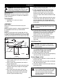
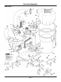
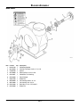
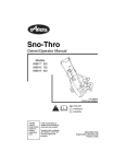
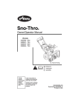
Promaster 310 Grass Catcher
Owner/Operator & Parts Manual
Model
890015*
*NOTE: Installation requires a separate mower boot kit,
p/n 04916000 for 60" decks, p/n 04916100 for 50" decks.
08493200A 12/03
Supercedes 08493200
Printed in USA
TABLE OF CONTENTS
Safety . . . . . . . . . . . . . . . . . . . . . . . . . . . . . . . . . . . 3
Storage. . . . . . . . . . . . . . . . . . . . . . . . . . . . . . . . . . 9
Assembly . . . . . . . . . . . . . . . . . . . . . . . . . . . . . . . . 6
Troubleshooting . . . . . . . . . . . . . . . . . . . . . . . . . . 9
Operation . . . . . . . . . . . . . . . . . . . . . . . . . . . . . . . . 7
Parts List . . . . . . . . . . . . . . . . . . . . . . . . . . . . . . . 10
Maintenance . . . . . . . . . . . . . . . . . . . . . . . . . . . . . 8
Warranty. . . . . . . . . . . . . . . . . . . . . . . . . . . . . . . . 13
INTRODUCTION
THE MANUAL
DISCLAIMER
Before operation of unit, carefully and completely read
your manuals. The contents will provide you with an
understanding of safety instructions and controls
during normal operation and maintenance.
All reference to left, right, front, or rear are given from
operator sitting in operation position and facing the
direction of forward travel.
Ariens reserves the right to discontinue, make changes
to, and add improvements upon its products at any time
without public notice or obligation. The descriptions
and specifications contained in this manual were in
effect at printing. Equipment described within this
manual may be optional. Some illustrations may not be
applicable to your unit.
MODEL AND SERIAL NUMBERS
DELIVERY
When ordering replacement parts
or making service inquiries, know
the Model and Serial numbers of
your unit.
Numbers are located on the product
registration form in the unit literature
package. They are printed on a
serial number label, located on the
frame of your unit.
Record Unit Model and Serial numbers here.
Transfer
model & serial
number label
from product
registration
here.
•
Customer Note: If you have purchased this product
without complete assembly and instruction by your
retailer, it is your responsibility to:
1. Read and understand all assembly instructions in
this manual. If you do not understand or have
difficulty following the instructions, contact your
nearest Gravely Dealer for assistance. Make sure
all assembly has been properly completed and
safety interlock system works properly.
NOTE: To locate your nearest Gravely Dealer, call
800-472-8359 or go to www.gravely.com on the
internet.
WARNING: Improper assembly or
adjustments can cause serious injury.
UNAUTHORIZED REPLACEMENT PARTS
Use only Gravely replacement parts. The replacement
of any part on this vehicle with anything other than an
Gravely authorized replacement part may adversely
affect the performance, durability, or safety of this unit
and may void the warranty. Gravely disclaims liability
for any claims or damages, whether warranty, property
damage, personal injury or death arising out of the use
of unauthorized replacement parts.
PRODUCT REGISTRATION
The Gravely dealer must register the product at the
time of purchase. Registering the product will help the
company process warranty claims or contact you with
the latest service information. All claims meeting
requirements during the limited warranty period will be
honored, whether or not the product registration card is
returned. Keep a proof of purchase if you do not
register your unit.
Customer Note: If Dealer does not register your
product, please fill out, sign and return the product
registration card to Gravely.
GB - 2
2. Understand all Safety Precautions provided in the
manuals.
3. Review control functions and operation of the
unit. Do not operate unit unless all controls
function as described in this manual.
4. Review recommended lubrication, maintenance
and adjustments.
5. Fill out Original Purchaser Registration Card and
return the card to Gravely Company.
© Copyright 2001, 2003 Ariens Company
SAFETY
SAFETY ALERTS
SAFETY DECALS AND LOCATIONS
Look for these symbols to point out
important safety precautions. They mean:
ALWAYS replace missing or damaged Safety Decals.
Refer to Parts List for Safety Decal locations.
Attention!
Danger! - To Avoid Serious Injury
Personal Safety Is Involved!
Become Alert!
Obey The Message!
The safety alert symbols above and signal words below
are used on decals and in this manual.
Read and understand all safety messages.
OL0900
DANGER: IMMINENTLY HAZARDOUS
SITUATION! If not avoided, WILL RESULT in
death or serious injury.
OL0910
ROTATING FAN! Stop grass pump and
power unit engines before removing any
part of bagger. Wait for all moving parts to
stop.
DO NOT operate mower unless guards
are in place or grass pump and entire
bagger are attached.
Stop engines and wait for all moving parts
to stop before opening cover.
Keep children and others away from unit
while operating.
WARNING: POTENTIALLY HAZARDOUS
SITUATION! If not avoided, COULD RESULT
in death or serious injury.
OL4140
ALWAYS wear adequate hearing
protection.
CAUTION: POTENTIALLY HAZARDOUS
SITUATION! If not avoided, MAY RESULT in
minor or moderate injury. It may also be used
to alert against unsafe practices.
OL4690
Avoid tip over and loss of control:
DO NOT overload bagger.
Use extreme caution on slopes.
DO NOT make abrupt turns or speed
changes.
Be aware of new turning radius.
NOTATIONS
NOTE: General reference information for proper
operation and maintenance practices.
IMPORTANT: Specific procedures or information
required to prevent damage to unit or attachment.
Caution - Grass Catcher
PRACTICES AND LAWS
Practice usual and customary safe working
precautions, for the benefit of yourself and others.
Understand and follow all safety messages. Be alert to
unsafe conditions and the possibility of minor,
moderate, or serious injury or death. Learn applicable
rules and laws in your area. Always follow the practices
set forth in this manual.
Stop engine or motor before attaching or
removing grass catcher. Under normal
use the catcher bag material is subject to
wear and deterioration and should be
checked to insure compliance with
original manufacturer specifications.
Boot Danger - Rotating Blades
REQUIRED OPERATOR TRAINING
Original purchaser of this unit was instructed by the
seller on safe and proper operation by the seller. If unit
is to be used by someone other than original
purchaser; loaned, rented or sold, ALWAYS provide
this manual and any needed safety training before
operation.
Keep feet and hands clear.
OL5000
Boot Caution - Rotating Blades
Stop engine before removing or cleaning
this chute. Keep hands and feet clear!
Rotating blades!
GB - 3
Warning - Engine
Dust, fog, etc. can reduce vision and cause an
accident. Operate unit only when there is good visibility
and light.
DO NOT operate in poorly ventilated area.
DO NOT refuel while engine is running.
Make sure no flame/spark around during
refuel.
DO NOT touch exhaust system and
engine while hot.
DO NOT touch spark plug cap or high
tension cord during engine running.
*SEE YOUR OPERATOR’S MANUAL.
Personal Safety
ASSEMBLY SAFETY RULES
Read, understand, and follow all safety practices in
Owner/Operator Manual before beginning assembly.
Failure to follow instructions could result in personal
injury and/or damage to unit.
ALWAYS remove key and wire from spark plugs on unit
before assembly. Unintentional engine start up can
cause death or serious injury.
Sharp edges can cut. Movement of parts can cut off
fingers or a hand. Wrap blade(s), wear sturdy gloves
and use extreme caution when working near blades.
Installing the grass catcher on your mower
requires the removal of the discharge chute
deflector. Retain discharge chute and
hardware in a safe location and reinstall
whenever operating unit without the grass
pump. DO NOT operate mower unless guards
are in place or grass pump and entire bagger
are attached.
Only trained adults may operate unit.
Training includes actual operation.
NEVER operate unit after or during the use of
medication, drugs or alcohol. Safe operation requires
your complete and unimpaired attention at all times.
NEVER allow anyone to operate this unit when their
alertness or coordination is impaired.
Wear adequate safety gear and protective gloves.
Wear proper footwear to improve footing on slippery
surfaces.
DO NOT wear loose clothing or jewelry and tie back
hair that may get caught in rotating parts.
Protect eyes, face and head from objects that may be
thrown from unit. Wear appropriate hearing protection.
Avoid sharp edges. Sharp edges can cut. Moving parts
can cut off fingers or a hand.
ALWAYS keep hands and feet away from all rotating
parts during operation. Rotating parts can cut off body
parts.
NEVER place your hands or any part of your body or
clothing inside or near any moving part while unit is
running.
ALWAYS disengage attachment, stop unit and engine,
remove key and allow moving parts to stop before
leaving operator’s position.
Operation
OPERATIONAL SAFETY RULES
Walk Around Inspection
Complete a walk around inspection of unit and work
area to understand:
• Work area • Your unit • All safety decals
Work Area
ALWAYS check overhead and side clearances carefully
before operation. ALWAYS be aware of traffic when
operating along streets or curbs.
Keep children and people away. Keep children out of
work area and under watchful care of a responsible
adult.
NEVER allow children to operate or play on or near
unit. Be alert and shut off unit if children enter area.
Keep area of operation clear of all toys, pets, and
debris. Thrown objects can cause injury.
Check for weak spots on docks, ramps or floors. Avoid
uneven work areas and rough terrain. Stay alert for
hidden hazards.
Avoid uneven and rough terrain. DO NOT operate near
drop offs, ditches, or embankments. Unit can suddenly
turn over if a wheel is over the edge of a cliff or ditch, or
if an edge caves in.
Understand:
• How to operate all controls
• The functions of all controls
• How to STOP in an Emergency
• Braking and steering characteristics
• Turning radius and clearances
NEVER operate bagger if the tractor’s safety interlock
system is not working properly.
Always be aware of maximum sweep of catcher when
turning. Always allow adequate clearance between
catcher, personnel and other objects when turning.
As grass catcher fills, be alert to changing unit stability
and control.
Disengage PTO when attachment is not in use.
ALWAYS disengage PTO, stop unit and engine,
remove key, engage parking brake and allow moving
parts to stop before leaving operator’s position.
DO NOT operate at too fast a rate. DO NOT change
engine governor settings or over-speed engine. Slow
down before turning.
DO NOT mow near dropoffs, ditches or embankments.
The mower could suddenly turn over if a wheel is over
the edge of a cliff or ditch, or if an edge caves in.
DO NOT mow on wet grass. Reduced traction could
cause sliding.
GB - 4
DO NOT try to stabilize the machine by putting your
foot on the ground.
Know the weight of loads. Limit loads to those you can
safely control and the unit can safely handle.
ALWAYS keep protective structures, guards and panels
in good repair, in place and securely fastened.
DO NOT operate in reverse unless absolutely
necessary. ALWAYS look down and behind before and
while backing.
Watch for holes, ruts, or bumps. Uneven terrain could
overturn the machine.
ALWAYS allow adequate clearance for unit,
attachments, operator and objects in work area when
turning. Slow down before turning.
NEVER carry passengers.
Hazardous Slopes
If you cannot back up a slope or you feel uneasy on it,
do not mow it.
Mow up and down slopes, not across them.
Keep all movements on the slope slow and gradual.
DO NOT make sudden changes in speed or direction.
Avoid starting or stopping on a slope. If tires lose
traction, disengage the blades and proceed slowly
straight down the slope.
DO NOT operate on slopes over 10˚.
DO NOT park on slopes unless absolutely necessary. If
you must park on a slope, always chock or block
wheels. Always set parking brake.
Transport
Use extra care when loading or unloading unit onto
trailer or truck.
Secure unit chassis to transport vehicle. NEVER
secure from rods or linkages that could be damaged.
DO NOT transport machine while engine is running.
ALWAYS turn off power to attachment when
transporting.
Keep all hardware properly tightened.
Cleaning
Keep unit free of debris. Clean up oil or fuel spills.
STORAGE SAFETY RULES
DO NOT store grass can with grass in them.
For extended storage, clean unit thoroughly. See
Engine Manual for proper storage.
ALWAYS lower cutting deck when unit is parked or
stored.
FUEL SAFETY RULES
Fuel is highly flammable and its vapors are explosive.
Handle with care. Use an approved fuel container.
NO smoking, NO sparks, NO flames. ALWAYS allow
engine to cool before servicing.
NEVER fill fuel tank when engine is running or hot from
operation.
NEVER fill or drain fuel tank indoors.
Replace fuel cap securely and clean up spilled fuel.
ACCESSORY AND ATTACHMENT SAFETY
RULES
Use only attachments or accessories designed for your
unit and properly installed.
Check attachment components frequently. If worn or
damaged, replace with manufacturer’s recommended
parts.
Grass catcher components are subject to wear,
damage, and deterioration, which could expose moving
parts or allow objects to be thrown. Frequently check
components and replace with manufacturer’s
recommended parts, when necessary.
MAINTENANCE AND SERVICE SAFETY
RULES
Disengage PTO, stop engine, remove key and wait for
all moving parts to stop before servicing, making
repairs, adjusting or when clearing debris.
ALWAYS block wheels. Know all jack stands are
strong, secure and will hold weight of unit during
maintenance.
ALWAYS keep protective structures, guards, and
panels in good repair, in place and securely fastened.
NEVER modify or remove safety devices.
Fumes from engine exhaust can cause injury or death.
DO NOT run engine in an enclosed area. Always
provide good ventilation.
Keep unit free of grass, leaves, or other debris. Clean
up oil or fuel spills.
Check grass can and catcher parts prior to each use
for any holes, abrasions, mildew, or structural damage.
Replace parts when necessary.
GB - 5
ASSEMBLY
5. Fasten catcher tube to the tube bracket. Use the
two holes nearest the tube end.
6. Fasten ring weldment (item #35) to the pivot
bracket weldment. With the ring in the raised
position, place the grass can on the catcher
weldment (item #50). Lower the ring onto the
grass can. Tighten the hardware installed in step
3 above.
7. Connect the catcher tube to the inlet on the grass
catcher cover (item #29). Raise the ring and pull
the cover inside the ring. Fold the edge of the
cover around the ring and secure with the snaps
on the cover.
WARNING: AVOID INJURY. Read and
understand Assembly Safety Rules in Safety
section before attempting to assemble unit.
Unpacking Unit
IMPORTANT: Remove contents from carton carefully.
Place cover assembly on a flat piece of cardboard to
avoid scratching it.
Tools Required
•
•
Wrenches: 1/2", 9/16", 3/4", 15/16"
Drill: 11/16"
ASSEMBLY
CAUTION: When emptying grass can,
always remove hold down strap from ring
weldment.
Refer to Parts section for illustrations and parts
locations.
NOTE: Installation requires a separate mower boot kit,
p/n 04916000 for 60" decks, p/n 04916100 for
50" decks.
NOTE: For units before serial number 500, drill two
11/16" diameter holes in the right side frame as shown
in Figure 1. It may be necessary to cut an access hole
in the side of the footrest to mark and drill the rear hole.
8. Put one end of the hold down strap (item #36)
through the hole on the catcher weldment. Bend
the S-hook so it cannot snap out of the hole.
Hook the other end of the hold down strap
through the tab on the ring weldment.
9. Put the hose adapter (item #19) in place at the
blower inlet and retain with two locking handles
(item #20).
Install Mower Boot
WARNING: Never operate mower without
discharge chute deflector or complete grass
catcher installed.
1"
Access hole
1. Remove discharge chute deflector from mower
deck. Keep discharge chute and hardware to
reinstall when bagger gets removed.
2. Fasten boot bracket to mower boot.
3. Place the mower boot over the discharge opening
and fasten to deck with boot bracket.
7-7/16"
18-3/8"
Figure 1
OFf0200
Connect Bagger to Unit
Assemble Grass Catcher Weldment
1. Attach bagger adapter plate (item #52) to right
side of unit frame.
2. Attach catcher mount weldment (item #45) to
bagger adapter plate.
3. Fasten tube bracket (item #32) and pivot bracket
weldment (item #34) to upright. Do not tighten
hardware yet.
4. Slip a clamp over each end of catcher tube
(item #5). Put one end over blower (item #23)
outlet flange and the other end onto the tube
bracket. Tighten the bottom clamp.
GB - 6
1. Connect catcher weldment to catcher mount with
klik pins (item #44).
2. Connect the blower hose (item #59) to the blower
inlet and secure with clamp.
3. Connect the blower hose to the mower boot and
secure with clamp.
CAUTION: Deflected material may cause
injury. ALWAYS operate mower with bagger
cover closed and secured with hold down
strap, grass pump assembly fastened
securely or with discharge chute deflector in
operating position.
REMOVING BAGGER
3. Remove mower boot from deck.
4. Replace original discharge chute deflector.
1. Disconnect hose from blower inlet and mower
boot.
2. Remove klik pins from catcher weldment and
remove catcher from unit.
OPERATION
BAGGING
WARNING: AVOID INJURY. Read and
understand Operational Safety Rules in
Safety section before operating.
Starting
IMPORTANT: ALWAYS start grass catcher engine
before starting unit engine.
1. Start grass catcher engine per engine manual
instructions.
2. Set grass catcher engine throttle to fastest speed.
Throttle Lever
Move lever to FAST (1) position to
increase engine speed. Move lever to
SLOW (2) position to decrease engine
speed.
1
2
NOTE: An automatic clutch controls grass pump fan
engagement and speed. Increasing engine speed
engages the clutch and increases fan speed.
3. Start unit engine and engage PTO according to
unit owner’s manual.
4. Set unit throttle to fastest speed.
5. Choose a slow ground speed.
OE0340
NOTE: An automatic clutch controls grass pump fan
engagement and speed. Increasing engine speed
engages the clutch and increases fan speed.
Choke
Pull choke control out to start a cold engine.
Push control in as engine warms up.
Shut Off
1. Disengage PTO.
2. Shut off unit according to unit owner’s manual.
3. Shut off grass catcher engine and wait for all
moving parts to stop.
OE0590
Engine Switch
EMPTYING GRASS CAN
Turn switch to On to start engine.
Turn switch to Off to shut-off engine.
OFF
If catcher stops picking up grass clippings, grass can
may be full.
To empty grass can:
1. Disengage PTO, stop unit engine and remove
ignition key. Wait for all moving parts to stop
before leaving operator’s position.
2. Stop grass catcher engine. Wait for all moving
parts to stop before touching catcher parts.
ON
Recoil Starter Handle
When pulled, handle will crank engine.
IMPORTANT: DO NOT let handle snap back against
unit.
BEFORE EACH USE
1. Check catcher parts for wear, deterioration or
damage. Replace ONLY with Gravely original
service parts before operating.
2. Ensure all hardware is tight.
3. Remove any grass build up from catcher parts.
4. Ensure hoses are secure to mower boot, grass
blower and catcher.
5. Place cover on grass can, close and secure cover
with hold down strap.
TO STOP IN AN EMERGENCY
Turn unit ignition key to OFF.
Turn grass catcher engine switch to OFF.
GB - 7
CAUTION: When emptying grass can,
always remove hold down strap from ring
weldment.
3.
4.
5.
6.
7.
Remove cover.
Remove grass can from catcher weldment.
Empty grass can.
Replace can on catcher weldment.
Close cover and secure can with hold down strap.
UNCLOGGING GRASS CATCHER
Stop grass catcher engine, wait for all moving
parts to stop and disconnect spark plug wire.
2. Loosen hose clamp on hose.
3. Remove hose from grass blower.
If clog is in hose:
1. Remove clogged grass.
2. Reinstall hose and tighten hose clamp.
If clog is in grass blower:
WARNING: MOVING PARTS can cut or
amputate body parts.
NEVER attempt to clear grass pump while
engine is running.
ALWAYS stop unit and grass catcher engines,
remove key, and wait for moving parts to stop.
Sharp edges can cut. Moving parts can cut off
fingers or a hand. Wrap blade(s), wear sturdy
gloves and use extreme caution when
working near blades or impeller.
WARNING: Impeller blades can cut or
amputate fingers or hands. Block impeller
blades to prevent rotation before proceeding.
WARNING: PINCH POINT! Use extreme
caution when unclogging grass blower.
Impeller can cut or pinch your hand, even
when not in operation. Wear sturdy gloves
when working near impeller.
1. Remove hose adapter.
2. Clear grass from blower.
3. Reinstall hose adapter and hose and tighten hose
clamp.
If hose or grass blower gets clogged, stop forward
motion and allow unit to clear itself. If unit will not clear
itself, unclog the hose/grass blower manually as
instructed below.
To unclog:
1. Stop unit engine and remove ignition key. Wait for
all moving parts to stop.
OPERATING TIPS
•
•
•
•
Cut grass when it is dry.
Cut grass in two passes when cutting thick, long
or wet grass. Make the first cut higher than
desired. Make the second cut at desired height.
Always use full throttle when bagging.
Clean deck after each use to reduce clogging.
MAINTENANCE
Gravely Dealers will provide any service or
adjustments which may be required to keep your unit
operating at peak efficiency.
MAINTENANCE SCHEDULE
Service Performed
WARNING: AVOID INJURY. Read and
understand Maintenance and Service in
Safety section before attempting any
maintenance.
Each
Use
Every 10
hrs.
Check Fasteners
•
Inspect Bagger Parts
•
Clean Unit
•
MAINTENANCE SCHEDULE
Check Engine Oil
•
The chart below shows the recommended
maintenance schedule that should be performed on a
regular basis.
Change Engine Oil
*
Check Belt
•
Lubricate Unit
•
Check Spark Plug
**
* Change engine oil according to manufacturer’s
recommendations. See engine manual for specific
instructions.
** See engine manual for schedule and specific
instructions.
CHECK FASTENERS
Be certain that all hardware is tight before each use.
Pay special attention to the guards and safety shields.
GB - 8
INSPECT CATCHER PARTS
Before each use, inspect grass catcher parts for any
holes, abrasions, or structural damage. Replace any
worn or damaged parts.
CLEAN UNIT
Clear away grass build up in catcher before and after
each use.
CHECK ENGINE OIL
Check engine oil before each use. See engine manual
for instructions.
CHANGE ENGINE OIL
See engine manual for oil change schedule and
instructions.
CHECK BELT
Check belt for wear and proper tension every 10 hours.
Replace belt if worn or deteriorated.
To replace:
1. Remove belt guard.
2. Loosen four bolts and lock nuts holding blower to
catcher weldment.
3. Loosen 3/8" jam nut.
4. Place new belt on grass pump drive pulley, idler
and deck pulley.
5. Adjust tension.
6. Replace belt guard.
To adjust tension:
1. Remove belt guard.
2. Loosen hardware securing bagger engine to
weldment.
3. Loosen four bolts and lock nuts holding blower to
catcher weldment.
4. Loosen 3/8" jam nut.
5. Turn the all-thread bolt until finger pressure of
5-10 lbs deflects the belt mid-section 1/4".
6. Move the engine closer to the power unit to
loosen the belt. Move it away from the power unit
to tighten the belt.
7. Tighten jam nut and engine bolts.
8. Replace belt guard.
LUBRICATE UNIT
Every 10 hours and before storage:
• Grease caster weldment.
CHECK ENGINE SPARK PLUG
Check and regap spark plug according to schedule in
engine manual.
STORAGE
WARNING: AVOID INJURY. Read and
understand Storage Safety Rules in Safety
section before operating.
IMPORTANT: NEVER spray unit with water. DO NOT
store unit outdoors.
Clean plastic surfaces with sponge and mild detergent.
Dry with a soft cloth.
Remove all debris from can and hoses before storing.
Remove all dirt, grease, leaves, etc. from unit.
Store in a clean, dry area.
Ensure all fasteners are properly tightened. Inspect
moving parts for damage and wear.
Touch up all rusted or chipped painted surfaces.
TROUBLESHOOTING
PROBLEM
PROBABLE CAUSE
CORRECTION
Catcher fails to pickup
grass or leaves.
1.
2.
3.
4.
Grass can is full.
Catcher is clogged.
Deck is clogged.
Mowing too fast for conditions.
Impeller stops or
slows.
1. Worn or damaged belt.
GB - 9
1. Shut off engine, remove key and empty
grass can.
2. See Unclogging Grass Catcher in
Operation.
3. Remove clog according to deck’s
Operator Manual.
4. Mow slower.
1. Replace belt.
CATCHER ASSEMBLY
Model 890015
PF2100
GB-10
CATCHER ASSEMBLY
Model 890015
Item
1
2
3
4
5
6
7
8
9
10
11
12
13
14
15
16
17
18
19
20
21
22
23
24
25
26
27
28
29
30
31
32
Part No.
03444800
05946900
06437200
06529800
09032500
08941700
05946800
06308400
06437300
08266600
06609600
06435700
05947300
06308600
07221100
08941500
06431900
05937400
04914351
03444800
05958900
06536300
69005000
08970200
05959400
07009000
06436200
06529600
08944900
05958400
05963300
08942700
Qty.
2
2
10
6
1
1
2
2
2
1
1
1
1
1
1
1
1
4
1
2
4
8
1
1
2
2
6
7
1
2
1
1
Description
Clamp
Bolt-Hex .31-18 x 1.00 Grade 5
Washer-Flat .344 x .688 x .065
Nut-Locking-Center .31-18
Tube-Catcher
Cover-Guard
Bolt-Hex .25-20 x .75 Grade 5
Washer-Locking .25 x .062
Washer-Flat-Steel .281 x .620 x .065
Engine, 5.5HP Kawasaki
Key-Hub .187 x 1.500
Washer-Flat-Steel .38 x .875 x .083
Bolt-Hex .31-24 x .75 Grade 5
Washer-Locking .31 x .078
V-Belt
Clutch
Race-Bearing-Thrust .060
Bolt-Hex .31-18 x 1.75 Grade 5
Weldment, Blower Adapter
Clamp-Screw
Bolt-Hex .50-13 x 1.25 Grade 5
Nut-Locking-Center .50-13
Assembly, PM-310 Blower
Guard
Bolt-Hex .38-16 x .75 Grade 5
Nut-Retainer
Washer-Flat .406 x .812 x .065
Nut-Locking-Center .38-16
Cover-Grass Catcher
Bolt-Hex .38-16 x 2.50 Grade 5
Bolt-Hex .38-16 x 2.00
Bracket-Tube
33
34
35
36
37
38
39
40
41
42
43
44
45
46
47
48
49
50
51
52
53
54
55
56
57
58
59
60
61
62
08981100
08944600
08944300
07528100
08707400
05421600
06712600
05422400
07012800
06529400
05941300
07014500
08981700
08730400
05964100
07128500
08821900
08981800
1
1
1
1
1
1
1
2
1
1
1
2
1
1
2
2
2
1
04914451
04918051
06535300
05968700
05968100
05948700
06535800
04917500
*
*
**
1
1
2
2
2
2
2
1
1
1
1
Bushing .385 x .625 x 1.00
Weldment-Pivot Bracket
Weldment-Ring
Strap-Hold Down
Can-Grass
Race-Bearing-Thrust
Pin-Center .12 x 1.25
Bearing-Flanged
Fitting-Lube 90 Degree
Nut-Hex .38-16
Bolt-Hex Spec. .38-16 x 3.00
Pin-Klik
Weldment-Catcher Mount
Weldment-Castor
Bolt-Hex .50-13 x 5.50
Wheel-Wing Gauge
Bushing-Axle
Weldment-Catcher
Caution Label (part of item 29)
Plate, Bagger Adapter
Bracket, Boot Mounting
Nut-Locking-Center .62-11
Bolt-Hex .62-11 x 1.50 Grade 5
Bolt-Hex .62-11 x 2.00 Grade 5
Bolt-Hex .38-16 x 1.00 Grade 5
Nut-Locking-Nylon .38-16
Hose, Blower 8" x 40
Boot Decal, Danger
Boot Decal, Caution
Engine Decal, Warning
* Contact Peco Industries, 1-828-684-1234.
** Contact Kawasaki Technical Support, 1-800-433-5640.
GB-11
BLOWER ASSEMBLY
Model 890015
PF2100
Item
1
2
3
4
5
6
7
8
9
10
11
Part No.
03422100
06418500
21082200
05416000
04914851
05234600
03021500
06529800
06512000
05947000
03422000
Qty.
1
2
1
2
1
1
1
4
1
4
1
Description
Weldment-Spindle
Washer-Flat-Steel 1.015 x 1.5 x .125
Spacer
Bearing-Ball 1.0 x 2.0 x .56
Weldment, Fan Housing
Decal-Danger
Blade-Fan
Nut-Locking-Center .31-18
Nut-Locking-Jam 1.0-14
Bolt-Hex .31-18 x .75 Grade 5
Blade-Fan
GB-12
WARRANTY
2-Year Limited Warranty
Gravely Division of Ariens Company
655 West Ryan Street
P.O. Box 157
Brillion, WI 54110-0157
920-756-2141
Fax 920-756-2407
www.gravely.com
Gravely Division of Ariens Company (Gravely) hereby warrants to the
original consumer purchaser that all Gravely Two-Wheel,
Professional G, Pro, and ProMaster products will be free from defects
in material and workmanship for a period of two (2) years from the date
of purchase or 1000 hours, whichever comes first.
Protection Plan
Gravely will repair or replace any part found upon examination by
Gravely to be defective. Such repair or replacement will be free of
charge to the purchaser (labor and parts), except as noted below.
This warranty is subject to the following exceptions, conditions, and limitations:
Usage Requirement
The duration of this warranty shall be ninety days or 1000 hours, whichever comes first, if the product is rented or leased.
Purchaser’s Responsibilities
• The purchaser must perform maintenance and minor
adjustments per the operator’s manual.
• The purchaser must notify Gravely or an authorized Gravely
service representative of the need for warranty service.
• The purchaser must transport the product to and from the place
of warranty repair.
Product Registration
• Returning the product registration card to Gravely will enable
the company to contact the registrant with repair or replacement
part information.
Service Parts and Accessories
• Service parts and accessories not purchased with the product
covered by this warranty are warranted to be free of defects
for a period of ninety (90) days following the date of purchase,
and will be replaced free of charge (except for labor).
Service
• Warranty service must be done by an authorized Gravely dealer.
To find an authorized Gravely service representative, contact
Gravely at the website, number or address above.
Battery Warranty Prorated
• One to three months - Free replacement
• Four to twelve months - Prorated over 12 months
Exclusions (No Warranty)
• Normal maintenance, services, and normal replacement items,
such as spark plugs, oil, oil filters, air filters, mufflers, belts,
tires, shoes, runners, scraper blades, shear bolts, mower blades,
mower vanes, headlights, light bulbs, knives, etc. are not covered
by this warranty.
• Any equipment which has been altered, misused, misassembled,
improperly adjusted, neglected, or damaged by accident is not
covered by this warranty.
• Service completed by someone other than an authorized
Gravely dealer is not covered by this warranty.
• Any attachment not approved by Gravely nor any parts that
are not genuine Gravely service parts are not covered by this
warranty.
• Engines and engine accessories are covered only by the
warranty made by the engine manufacturer, and are not covered
by this warranty.
• If the product is equipped with a Hydro-Gear transmission
and/or Hydro-Gear drive components, the Hydro-Gear
transmission and/or drive components are covered only by the
warranty made by Hydro-Gear, and are not covered by this
warranty.
• This warranty applies only to products purchased in the United
States (including Puerto Rico) and Canada. In all other
countries, contact place of purchase.
Gravely may from time to time change the design of its products. Nothing contained in this warranty shall be construed as obligating
Gravely to incorporate such design changes into previously manufactured products, nor shall such changes be construed as an admission
that previous designs were defective.
LIMITATION OF REMEDY AND DAMAGES
Gravely’s liability under this express warranty, and under any implied
warranty that may exist, is limited to repair or replacement of any
defective part. In no event shall Gravely be liable for incidental,
special, or consequential damages (including lost profits). This
warranty gives you specific legal rights. You may also have other
rights which vary from state to state. Some states do not allow the
exclusion of incidental or consequential damages, or limitations
on how long an implied warranty lasts, so the above limitations
and exclusions may not apply to you.
DISCLAIMER OF FURTHER WARRANTY
Gravely makes no warranty other than what is
expressly made in this warranty. If the law of your
state provides that an implied warranty of
merchantability, or an implied warranty of fitness
for a particular purpose, applies to Gravely, any
such implied warranty is limited to the duration of
this express warranty.
Form: GLW2-122002
GB-13
GRAVELY
A Division of Ariens Company
655 West Ryan Street
P.O. Box 157
Brillion, WI 54110-0157
920-756-2141
Fax 920-756-2407
www.gravely.com