1
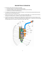
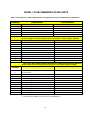
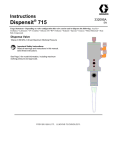
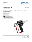
Instructions Dispensit - 710 332094A EN Usage Statement – Depending on valve configuration this valve can be used to dispense the following: Acrylics • Conformal Coatings • Epoxies • Lubricants • RTV Silicones • Silicone Oils • Solder Flux • Solder Mask • UV Curables Dispense Valve 100psi (0.69 MPa, 6.9 bar) Maximum Working Pressure No.)OartPartMeteri Important ng Unit ( Safety Instructions Read all warnings and instructions in this manual. Save these instructions. See Page 3 for model information, including maximum working pressure and approvals. DISPENSIT® MODEL 710 DISPENSE VALVE OPERATING & MAINTENANCE MANUAL General Information................................................................................... 3 Safety Information ..................................................................................... 3 Illustration References .............................................................................. 3 General Accessories ................................................................................. 3 Description Of Operation .......................................................................... 4 Setup Procedure ........................................................................................ 5 Mounting Dispense Valve ......................................................................... 5 Air Controller............................................................................................. 5 Operating Procedures ............................................................................... 5 Dry System Checkout .............................................................................. 5 Material Loading ...................................................................................... 6 Remote Mounted Material Supply........................................................ 6 Valve Mounted Syringe Material Supply .............................................. 6 Wet System Checkout ............................................................................. 6 Operation Adjustments ............................................................................ 6 Air Supply Adjustment ........................................................................ 6 Material Output Adjustment ................................................................ 6 Dispense Needle Height Adjustment .................................................. 6 Periodic Maintenance ................................................................................ 7 Dispense Needle Replacement ............................................................... 7 Disassembly ............................................................................................ 7 Model 710 General Illustration ................................................................. 8 Assembly ................................................................................................. 9 Troubleshooting ........................................................................................ 10 Model 710 Recommended Spare Parts .................................................... 11 General Guidelines for O-rings and U-cup Seals .................................... 12 Warranty ..................................................................................................... 13 GENERAL INFORMATION The Model 710 Dispense Valve is an On/Off valve designed for a continuous flow of viscous material through a dispense needle in automatic, semi-automatic or manual applications. It is shipped complete with the following: Model 710 Dispense Valve Two 3 foot (.9 m) sections of pneumatic air line Seal Kit Operating and Maintenance Manual SAFETY INFORMATION This product should be used only by employees who have been given appropriate training and safety warnings as set forth in this manual. Read completely before operating. WARNING: Do not exceed 100 psi (6.9 bar) pressure on the operating system. Do not exceed 1200 psi (82.7 bar) material inlet pressure. Higher pressures may cause a hazard or serious injury. Note: The minimum recommended pneumatic operating system pressure is 70 psi (4.8 bar) clean/dry air. Toxicity and flammability hazards depend upon the product being dispensed by this unit, and the user should take appropriate safety precautions as indicated on the MSDS of the product. Always wear safety glasses. ILLUSTRATION REFERENCES Throughout this manual you will find references by illustration item number to the illustrations in the manual. The references are indicated by parentheses around a number such as: (7). Illustrations represent typical valve configurations. The drawings for your exact model are inserted at the back of the manual and include the part numbers for ordering replacement parts. GENERAL ACCESSORIES Graco | Liquid Control offers a full line of standard and custom accessories for your dispensing needs including: Valve Controllers Syringe Feed Systems Cartridge Retainers and Pressure Reservoirs Titan 200 High Pressure Cartridge Feed Systems Transfer Pump Feed Systems for 1, 5 and 55 gallon containers Mounting Bases and Brackets Custom Needles and Needle Blocks Consult your Dispensit dealer or the factory for details. 3 DESCRIPTION OF OPERATION 1. The normal “ready” state of the system is as follows: The material supply line is filled with dispensable material. The system has been purged, filling the valve with material up to the Piston(4). The Piston (4) is seated in the Needle Seat (1). 2. The dispense cycle begins when the controller is activated. Air at 70 psi (4.8 bar) enters the Open port and raises the Piston (4) off the Needle Seat (1). 3. Material flows through the Valve Body (5) and out through the Needle Block (23). Volume can be varied by changing the material pressure, needle size, dispense speed and dispense time. 4. When the correct amount of material has been dispensed, the controller relieves air from the Open port and applies air to the Close port. The Piston (4) seats back into the Needle Seat (1), sealing the valve and ending the dispensing process. The system is again in the normal “ready” state. 4 SETUP PROCEDURE MOUNTING DISPENSE VALVE Mounting holes are drilled through the valve body. The valve may be tilted to a maximum of 60 degrees from the vertical depending on the application. AIR CONTROLLER Operation of the Model 710 Dispense Valve requires a controller that can provide the following: 3 A minimum of 0.5 SCFM (2.3 cm ) of dry unlubricated air at a minimum pressure of 70 psi (4.8 bar) and a maximum of 100 psi (6.9 bar). Time delay capability to allow the valve to cycle. Independent air pressure regulators for material supply and valve operation. “Purge capability” which is the ability for the operator to pass or not pass air to the Open port on the dispense valve. For semiautomatic or automatic applications, a foot switch or other control to cycle the valve. Connection for .16”ID x .25” OD (6.35mm) pressure tubing for use between the dispense valve and controller. Connection for a .16”ID x .25” OD (6.35mm) pressure tubing for use between the controller and syringe. OPERATING PROCEDURES If there are any problems in getting started, refer to the Troubleshooting section or call Technical Service at (330) 494-1313. DRY SYSTEM CHECKOUT This is an initial checkout to determine if the setup has been properly completed. The dry checkout is conducted without any material in the system. Refer to the illustrations above or below. 1. Turn on the controller and the air supply. 2. Set the air pressure to 70 psi (4.8 bar) on the system pressure gauge. 3. In the normal “ready” state the Piston (4) is seated in the Needle Seat (1), sealing the dispense valve. For this test, loosen the Nut (2) and remove the Needle Block (23) and Needle Seat (1) so that you can visually verify that the Piston (4) rises inside the Valve Sleeve (3). 4. Momentarily press the dispense valve cycling control switch. 5. The controller applies air to the Open port of the dispense valve, the Piston (4) lifts. After the time delay the controller applies air to the Close port causing the Piston (4) to move down. Visually verify the piston movement. When this happens, the system is correctly installed. 6. Reinstall the Needle Block (23) and Needle Seat (1) with the Nut (2). Anytime the Needle Seat (1) is replaced, you must loosen the Hex Nut (20) and tighten the Adjustment Screw (21) into the Valve Body (5) until it seats. Then back off the Adjustment Screw (21) approximately 2 turns and tighten the Hex Nut (20). This step is required for proper adjustment of the Piston (4). 5 OPERATING PROCEDURES MATERIAL LOADING Material is supplied from a pressure vessel or pump with enough pressure to cause a proper rate of flow from the dispense needle. (Note: The material pressure will vary depending on the application.) Warning: Do not apply either operating or reservoir air pressure to the product unless all screws are in place and properly tightened and all material supply connections are properly in place and tightened. Fasten all air connections securely. Attach the air line to the regulator and set the air pressure control to the setting required for the application. (Note: When using a remote reservoir, the delivery tubing and fittings must be compatible with the material being dispensed and capable of withstanding the dispensing pressure.) WARNING: Do not exceed 100 psi (6.9 bar) pressure on the operating system. Do not exceed 1200 psi (82.7 bar) material inlet pressure. Higher pressures may cause a hazard or serious injury. Note: The minimum recommended pneumatic operating system pressure is 70 psi (4.8 bar) clean/dry air. WET SYSTEM CHECKOUT Using the purge cycle on the air supply controller, run the material through the material supply line and valve until a smooth material flow is observed through the dispense needle. After the purge cycle has been completed, set the air supply controller to the manual cycle mode and cycle the dispense valve several times. OPERATION ADJUSTMENTS AIR SUPPLY ADJUSTMENT The air pressure to the controller and material supply regulator is typically 70 psi (4.8 bar). Do not exceed 100 psi (6.9 bar) pressure to the dispense valve. However, the material supply pressure must be adjusted according to the type of material being dispensed. Too low a pressure will give you an inconsistent dispensed volume because the material does not have sufficient pressure to flow smoothly through the needle. Too high a pressure may cause material separation or packing. Use the minimum pressure needed to obtain smooth material flow during the purge cycle. MATERIAL OUTPUT ADJUSTMENT The material output depends on the material pressure, size of needle, and the rate at which the dispense valve is moved by the system to which it is attached. Note: The Adjustment Screw (27) is used to adjust the maximum height setting of the Piston Rod (4) to the Needle Seat (1) and is not intended to be used as a flow control adjustment. See the Dry System Check (seen on the previous page) for more information. DISPENSE NEEDLE HEIGHT ADJUSTMENT Ideally, the material should just contact the work piece enough to create an adhesive bond and cause a clean separation of the material from the needle tip upon completion of the dispense cycle. 6 PERIODIC MAINTENANCE DISPENSE NEEDLE REPLACEMENT If no material or reduced volumes of material come out of the dispense needle it may be partially or completely clogged. Clean with water or solvent depending on the material dispensed. A fine wire, used cautiously, will help open clogged needles. Replace the needle if damaged or severely clogged. Replacement needles can be ordered for the Model 710 Dispense Valve by specifying the proper part number. See the Recommended Spare Parts section of this manual or consult the drawings for your exact model. DISASSEMBLY Refer to the illustration below and the drawings in the back of this manual for your exact model. Note the direction that u-cup and Posipak seals are facing as you remove them so that the replacements can be installed facing the same way. Note that the Gaskets (24) rarely require replacement and are not provided in the seal kit. Retain them for reuse after cleaning. Replacements are available from the factory or your Dispensit dealer. 1. 2. 3. 4. 5. 6. 7. 8. 9. 10. 11. 12. 13. 14. 15. 16. Turn off the air supply and remove the Connectors (28) from the controller. Turn off the material supply and remove the material inlet line from the Adapter (15). Remove the valve from its mounting. Remove the Needle Seat (1) and Needle Block (23) by removing the Nut (2). NOTE: Also remove the O-ring (18) and Gasket (24) associated with this needle seat. Save the gasket. Remove the Retaining Plug (17) which allows the Spring (13) to push the Valve Sleeve (3) and the Piston Assembly (4) out of the Valve Body (5). Remove the U-cup Seals (16). Remove the Set Screw (27) and remove End Cap (14) from the Valve Body (5). Loosen the Hex Nut (20) and remove the Adjustment Screw (21) and its O-ring (19) from the End Cap (14). Remove the O-rings (6) from the End Cap (14) and from the Valve Sleeve (3). Remove the Retaining Tube (9) from the Valve Sleeve (3). Remove the Retaining Ring (12) from the Valve Sleeve (3). Remove the Washer (11). Remove the U-cup Seal (10). Remove the Spacer (8). Remove the Posipak Seal (7). Remove the Tubing (29) from the open and close Elbows (25) and remove the elbows and their Gaskets (24). The 710 Dispense Valve is now ready for cleaning and assembly. 7 MODEL 710 GENERAL ILLUSTRATION 1 2 3 4 5 6 7 8 9 10 11 12 13 14 15 16 17 18 19 20 21 22 23 24 25 27 28 29 NEEDLE SEAT NUT VALVE SLEEVE PISTON ASSEMBLY VALVE BODY O-RING POSIPAK SEAL SPACER RETAINING TUBE U-CUP SEAL WASHER RETAINING RING SPRING END CAP 8 ADAPTER U-CUP SEAL RETAINING PLUG O-RING O-RING HEX NUT,#10-32 ADJUSTMENT SCRW,#10-32 X 1-1/2 FITTING NEEDLE BLOCK GASKET ELBOW SET SCREW CONNECTOR TUBING PERIODIC MAINTENANCE ASSEMBLY Refer to the illustration above and the drawings at the back of this manual for your exact model. Note: Clean all valve parts with an appropriate solvent prior to assembly. Always install new, lightly lubricated o-rings and seals when assembling the valve. Use Krytox 203GPL (part number 84/0200-K3/11) for lubricating valve parts including seals and o-rings. Lubricate the bore of the Valve Body (3) and the Valve Sleeve (3) before assembly. Check the Piston (4), Valve Sleeve (3) and Needle Seat (1) for wear and if they are worn secure replacements before proceeding. Note: Use caution as you install new U-cup and Posipak seals so that they are not pinched or torn. Do this by making sure they are lubricated, and by tucking the lips of the seal inward before uniformly pushing them into position. Always consult the illustrations and drawings to be sure that seals face the correct direction. 1. 2. 3. 4. 5. 6. 7. 8. 9. 10. 11. 12. 13. 14. 15. 16. 17. 18. Install the Posipak Seals (7) in the Valve Sleeve (3). Insert the Spacer (8). Install the U-cup Seals (10) in the Valve Sleeve (3). Align the Spacer (8) and insert the Retaining Tube (9) into the Valve Sleeve (3). Install the Washer (11) and the Retaining Ring (12) in the Valve Sleeve (3). Install the O-rings (6) on the Valve Sleeve (3) and on the End Cap (14). Install the End Cap (14) in the Valve Body (5). Secure the End Cap (14) with the Set Screw (27). Caution: Do not install the Adjustment Screw (21) at this time. Install the U-cup Seals (16) on the Piston Assembly (4) positioning them as noted in the illustration. Lubricate the piston rod and insert the Piston Assembly (4) into the Valve Sleeve (3). Place the Spring (13) on top of the Piston Assembly (4) and using the boss on the top of the piston to center the spring insert the Piston Assembly (4) and Valve Sleeve (3) into the Valve Body (5) until the spring compresses. Hold this in place firmly. Align and insert the Retaining Plug (17). Tighten the Retaining Plug (17) until it is snug. Do not overtighten. Carefully install the Needle Block (23) through the Gasket (24) and into the Needle Seat (1). Position the O-ring (18) on the Needle Seat (1) and place against the Valve Sleeve (3). Install the Nut (2) and tighten until snug. Do not overtighten. Lubricate the threads of the Adjustment Screw (21) and thread the Hex Nut (20) onto it fully. Insert the O-ring (19) into the End Cap (14). Thread the Adjustment Screw (21) and Hex Nut (20) into the End Cap (14) through the O-ring (19) until the Adjustment Screw stops. Back the Adjustment Screw (21) off two turns, then tighten the Hex Nut (20) down against the O-ring (19) and End Cap (14). Install the open port and close port Elbows (25) and their Gaskets (24). Install the Tubing (29). Mount the valve to its point of use. Connect the material inlet line to the Adapter (15). Attach the air supply line connectors (28) to the controller. Perform the Dry System Checkout, Material Loading and Wet System Checkout procedures. The 710S Dispense Valve is now ready to be placed back in service. 9 TROUBLESHOOTING If operating difficulties are encountered, review the symptoms below. With each problem there are one or more possible causes that should be investigated to resolve the situation. NOTHING HAPPENS - If absolutely nothing happens when trying to cycle the Dispense Head, check the electric pneumatic power. Check the footswitch or cycle start switch to be sure it is plugged in. VALVE CYCLES, NOTHING DISPENSED - First, try to purge the unit; this should fix most situations. If it doesn’t, check to see that there is enough pressure to the reservoir or transfer pump. Perhaps the Reservoir/Needle path is clogged; examine and clear or replace as necessary. Consider whether the material could have set up in the system. (See the “Wet System Checkout” and “Operation Adjustments” sections.) IRREGULAR VOLUME DISPENSED - Frequently, this is caused by faulty material. The material must be a smooth (homogeneous) mixture, without any air entrapped in it. A second cause could possibly be that the material is not being supplied. Check the reservoir pressure as it may be too low for the type of material being dispensed and/or the rate at which the system moves the dispense valve may be too fast. To adjust, follow the directions found in the “Operation Adjustments” section of this manual. REDUCED VOLUMES DISPENSED - Check to see if needle is partially clogged (refer to “Periodic Maintenance” section). NO MATERIAL DISPENSED - This is due to a clogged needle (refer to “Periodic Maintenance” section). MATERIAL CONTINUES TO FLOW AFTER SHUT OFF - This can be due to material preventing the piston from seating properly into the needle seat or to a worn piston and/or needle seat. Remove needle block and needle seat, clear the blockage or replace the worn components. 10 MODEL 710 RECOMMENDED SPARE PARTS Note: These parts are routine supply items or wear parts not covered by warranty for normal wear. Quantity 1 1 1 ** Description Part Number SEAL KIT,710 PISTON NEEDLE SEAT KRYTOX 203GPL ASSEMBLY LUBRICANT see assembly drawing for part number see assembly drawing for part number see assembly drawing for part number 84/0200-K3/11 #10-32 Hub Replacement Needles for Single Needle Block Models Quantity ** ** ** ** ** ** ** ** Needle Length is .75” from mounting face to needle tip. Custom lengths available. Description Needle Part Number NEEDLE, 12 GAUGE x .75”, Pack of 4 NEEDLE, 14 GAUGE x .75”, Pack of 4 NEEDLE, 16 GAUGE x .75”, Pack of 4 NEEDLE, 17 GAUGE x .75”, Pack of 4 NEEDLE, 18 GAUGE x .75”, Pack of 4 NEEDLE, 19 GAUGE x .75”, Pack of 4 NEEDLE, 20 GAUGE x .75”, Pack of 4 NEEDLE, 22 GAUGE x .75”, Pack of 4 A9010017-4 A9010019-4 A9010010-4 A9010011-4 A9010012-4 A9010013-4 A9010014-4 A9010020-4 Luer Lock Hub Replacement Needles for Single Needle Block Models Quantity ** ** ** ** ** ** ** ** ** ** Needle length shown is length projecting from LL hub. Other lengths available. Description Needle Part Number Needle Sampler Package, 10 each of 14, 16, 18, 20 and 22 Needle,LL,14 ga.x ½”, Pack of 50 * Needle,LL,14 ga.x 1”, Pack of 50 Needle,LL,15 ga.x ½”, Pack of 50 Needle,LL,16 ga.x ½”, Pack of 50 * Needle,LL,18 ga.x ½”, Pack of 50 * Needle,LL,19 ga.x ½”, Pack of 50 Needle,LL,20 ga.x ½”, Pack of 50 * Needle,LL,22 ga.x ½”, Pack of 50 * Needle,LL,23 ga.x ½”, Pack of 50 * Needles are included in Needle Sampler Package ** The quantity or needle size may vary for your application. 11 E4000025-50 E4000001-50 E4000014-50 E4000004-50 E4000088-50 E4000006-50 E4000008-50 E4000009-50 E4000011-50 E4000024-50 GENERAL GUIDELINES FOR O-RINGS AND U-CUP SEALS Sizes and materials of construction for O-rings and U-cup seals are selected by Graco Inc. based on compatibility with the chemicals to which they will be exposed. Solvents that may remove residual chemicals often have negative effects on the mechanical properties of O-rings and seals. O-Ring Guidelines Always replace an O-ring with the identical one in size, durometer hardness, type and material of construction. Always be alert to the location and size of each O-ring as many look alike and be careful not to mix them. Often similar sizes may be used in various locations on the equipment and if replaced incorrectly, the equipment may not function properly. Refer to the Machine Operation and Service Manual for the correct part number of all O-rings used throughout the equipment and replace them with factory approved parts only. Re-use of O-rings is not recommended. Only re-use O-rings as a last resort. If you must re-use them, be sure that they are clean, have no cuts or flat spots and contain NO foreign material. Also, be sure not to soak them in solvent for extended periods as this can cause deterioration of the O-ring. Always replace O-rings that are cut, nicked, or distorted in shape or cross-section. Always apply a very thin film of Krytox 203GPL lubricant, item 84/0200-K3/11, to the entire surface of the oring before installation. Avoid excessive lubrication. If installing O-rings over threads on a shaft or across sharp edges, roll or push the O-ring carefully into place being careful to avoid cutting or nicking it. Avoid stretching the O-ring too much as it may not return to the proper size. Do not use any sharp tools or objects to install O-rings U-cup Seal Guidelines Always replace a U-cup seal with the identical one in size, durometer hardness, type and material of construction. Always be alert to the location and size of each U-cup seal as many look alike and be careful not to mix them. Often similar sizes may be used in various locations on the equipment and if replaced incorrectly, the equipment may not function properly. Refer to the Machine Operation and Service Manual for the correct part number of all U-cups used throughout the equipment and replace them with factory approved parts only. Always apply a very thin film of Krytox 203GPL lubricant, item 84/0200-K3/11, to the inner and outer lips of the seal before installation. Re-use of U-cup seals is not recommended. Only re-use U-cups as a last resort. If you must re-use them, be sure that they are clean, have no cuts or flat spots and contain NO foreign material. Also, be sure not to soak them in solvent for extended periods as this can cause deterioration of the seal. Always replace U-cups that are cut, have flat spots, are distorted in shape or are damaged in any manner. Always be alert to the proper orientation of the sealing lips and re-install them in the same direction as shown on the specific equipment assembly drawing. The U-cup seals are intended to seal in only one direction and if installed incorrectly, chemical leakage through the U-cup can occur. Whenever possible, push the back side of the seal over the shaft to protect the inner and outer lips. If this is not possible, carefully tuck the lip in to avoid rolling it back or cutting it. If installing over sharp edges, slide the seal carefully into place to avoid cutting it. Do not use any sharp tools or objects to install U-cups. 12 Graco warrants all equipment referenced in this document which is manufactured by Graco and bearing its name to be free from defects in material and workmanship on the date of sale to the original purchaser for use. With the exception of any special, extended, or limited warranty published by Graco, Graco will, for a period of twelve months from the date of sale, repair or replace any part of the equipment determined by Graco to be defective. This warranty applies only when the equipment is installed, operated and maintained in accordance with Graco’s written recommendations. This warranty does not cover, and Graco shall not be liable for general wear and tear, or any malfunction, damage or wear caused by faulty installation, misapplication, abrasion, corrosion, inadequate or improper maintenance, negligence, accident, tampering, or substitution of nonGraco component parts. Nor shall Graco be liable for malfunction, damage or wear caused by the incompatibility of Graco equipment with structures, accessories, equipment or materials not supplied by Graco, or the improper design, manufacture, installation, operation or maintenance of structures, accessories, equipment or materials not supplied by Graco. This warranty is conditioned upon the prepaid return of the equipment claimed to be defective to an authorized Graco distributor for verification of the claimed defect. If the claimed defect is verified, Graco will repair or replace free of charge any defective parts. The equipment will be returned to the original purchaser transportation prepaid. If inspection of the equipment does not disclose any defect in material or workmanship, repairs will be made at a reasonable charge, which charges may include the costs of parts, labor, and transportation. . Graco’s sole obligation and buyer’s sole remedy for any breach of warranty shall be as set forth above. The buyer agrees that no other remedy (including, but not limited to, incidental or consequential damages for lost profits, lost sales, injury to person or property, or any other incidental or consequential loss) shall be available. Any action for breach of warranty must be brought within two (2) years of the date of sale. . These items sold, but not manufactured by Graco (such as electric motors, switches, hose, etc.), are subject to the warranty, if any, of their manufacturer. Graco will provide purchaser with reasonable assistance in making any claim for breach of these warranties. In no event will Graco be liable for indirect, incidental, special or consequential damages resulting from Graco supplying equipment hereunder, or the furnishing, performance, or use of any products or other goods sold hereto, whether due to a breach of contract, breach of warranty, the negligence of Graco, or otherwise. The Parties acknowledge that they have required that the present document, as well as all documents, notices and legal proceedings entered into, given or instituted pursuant hereto or relating directly or indirectly hereto, be drawn up in English. Les parties reconnaissent avoir convenu que la rédaction du présente document sera en Anglais, ainsi que tous documents, avis et procédures judiciaires exécutés, donnés ou intentés, à la suite de ou en rapport, directement ou indirectement, avec les procédures concernées. For the latest information about Graco products, visit www.graco.com. 612-623-6921 contact your Graco distributor or call to identify the nearest distributor. 1-800-746-1334 330-966-3006 • Minneapolis Belgium, China, Japan, Korea • www.graco.com •