1
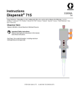
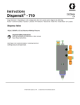
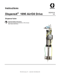
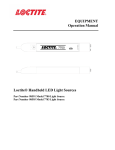
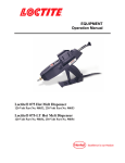
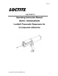
EQUIPMENT
Operation Manual
Loctite® MMD Dispense Valve Manual
Part Number
989027, 1:1 - 5:1 Abrasion Resistant
989096, 1:1 - 5:1 Stainless Steel
989098, 5.05:1 – 10:1 Stainless Steel
989099, 5.05:1 – 10:1 Abrasion Resistant
Table of Contents
1 Please Observe the Following ..................................................................................................................3
1.1
1.2
Emphasized Sections...........................................................................................................................................3
For Your Safety...................................................................................................................................................3
2 Description...........................................................................................................................................................4
3 Installation ...........................................................................................................................................................4
3.1
3.2
Tools Required for Installation and Maintenance ...............................................................................................4
Installation Procedure..........................................................................................................................................4
4 Operation ..............................................................................................................................................................5
4.1
4.2
Dispensing Material ............................................................................................................................................5
Shut Down...........................................................................................................................................................5
5 Troubleshooting ................................................................................................................................................6
6 Care and Maintenance ..................................................................................................................................6
6.1
Routine Maintenance ..........................................................................................................................................6
7 Troubleshooting ................................................................................................................................................7
8 Recommended Spare Parts.........................................................................................................................7
9 Exploded Diagram ..........................................................................................................................................9
10 Warranty .........................................................................................................................................................11
1
Please Observe the Following
1.1
Emphasized Sections
Warning!
Refers to safety regulations and requires safety measures that protect the operator or other
persons from injury or danger to life.
Caution!
Emphasizes what must be done or avoided so that the unit or other property is not damaged.
Notice:
Gives recommendations for better handling of the unit during operation or adjustment as
well as for service activities.
1.2
For Your Safety
WARNING!
Always wear safety glasses when operating the Loctite® MMD Dispense Valve.
WARNING!
Always aim the Loctite® MMD Dispense Valve at the work – never at other people.
WARNING!
100-PSI maximum inlet air pressure. Use a known regulated dry air source only.
WARNING!
Read all material manufacturer’s product information. Always follow material
manufacturers specific recommendations regarding dispensing even if they may differ
from these general instructions.
WARNING!
Although the Loctite® MMD Dispense Valve minimizes user contact with materials,
always read and abide by information provided in material manufacturer’s MSDS
(Material Safety Data Sheet). Keep the MSDS accessible to the work area as it lists
valuable emergency information.
WARNING!
Consult local, state and federal laws before disposing of mixers or material.
WARNING!
Do not operate if any of the Loctite® MMD Dispense Valve's components are missing
or damaged.
The unit may be repaired only by an authorized Loctite service representative.
2
Description
The pneumatically actuated Loctite® MMD Dispense Valve is designed to isolate materials
until they have reached the disposable Static mix nozzle inlet. The "A" and "B" components
enter through individual shut off spool valves and pass through the Loctite® MMD
Dispense Valve in separate streams. Upon exiting the Loctite® MMD Dispense Valve nose,
the "A" and "B" materials converge in the Static mix nozzle and are thoroughly blended
prior to reaching the mixer outlet. A wide selection of Static mix nozzles is available to
accommodate most materials, ratios, viscosities and flow rates.
The shut off valve rods are operated together for synchronization of the two streams, and
when closed, the valve rod spools create a snuff back in the outlet adapter and Static mix
nozzle which draws back material at the tip. The degree of snuff back is adjustable and can
thus be set to give optimum control of anti-drip and stringing between shots, depending on
material viscosity and pressure. Shut-off is positive and the large air cylinder drive gives a
snap-action on the open and close sequences.
A reverse acting version of the Loctite® MMD Dispense Valve is also available that does
not provide snuff back control.
3
Installation
3.1
Tools Required for Installation and Maintenance
• Snap Ring Pliers .070 Tip
• Standard Allen Wrench Set
• Standard Open End Wrench Set
• Medium Straight Head Screw Driver
3.2
Installation Procedure
1. Turn off the air supply and bleed off existing pressure.
2. Turn off the power source.
3. Disconnect the material feed lines.
4. Take caution to mark the material feed lines for proper "A" to "A" and "B" to
"B" connections.
5. Disconnect the air supply lines or remove the fittings.
6. Remove the old Loctite® MMD Dispense Valve mounting if applicable.
7. Install the new Loctite® MMD Dispense Valve.
8. Install the air supply lines. (Dry, Clean Air)
9. Install the material feed lines.
10. Take caution to connect "A" to "A" and "B" to "B".
11. Refer to the operations manual for priming the system.
12. Adjust the Snuff-Back if applicable.
13. Verify the pump's ratio accuracy and shot repeatability.
4
Operation
4.1
Dispensing Material
Operation of the Loctite® MMD Dispense Valve may be accomplished by one of
several methods using an open/close limit switch.
•
Lever Actuated
•
Hand Held Trigger Actuated
•
Foot Switch Actuated
•
Control Panel Actuated
Loctite® MMD Dispense Valve with Optional Hand Held
Trigger Assembly
4.2
Loctite® MMD Dispense Valve with Optional
Counter Balance and Lever Actuator Assembly
Shut Down
Proper shut down is important to the continued trouble-free operation of the
Loctite® MMD Dispense Valve.
1. Remove the Static mix nozzle and discard.
2. Wipe the excess material from the outlet block.
3. Ensure there has been no cross-contamination on the outlet block and dispense a
purge shot.
4. Install the white plug and retaining nut onto the outlet block when not in use.
5
Troubleshooting
TROUBLESHOOTING
Problem
No Flow
Leaks
Drools
Cause
Solution
Air Pressure too Low
Clogged Mixer
Dispense Valve (DV) Switch Closed
Seals not Seated
Seals Damaged
Worn Spool Rods
Air Trapped
Snuff-Back out of Adjustment
Requires 80 PSI Inlet Pressure
Replace the Mixer
Reset to Auto
Check the Seals
Replace the Seals
Replace Spool Rods and Seals
Review Start-up Procedure for Priming
Re-adjust the Snuff-Back (If Applicable)
Check Priming, Check-Valves, and/or
Pistons
Replace the Mixer
Check the Phasing at the Pumps
Off Ratio
Metering Pumps/System
Not Mixing
Fouled Mixer
Out of Phase Condition A:B
6
Care and Maintenance
Routine maintenance is important to the continued function of the Loctite® MMD Dispense
Valve. If maintenance is delayed or omitted, the Loctite® MMD Dispense Valve may not
operate properly.
If Loctite® MMD Dispense Valve contains grease fittings use approved grease,
grease monthly. Grease should exit from outlet ports on injection block. Do not over grease.
6.1
Routine Maintenance
• Replace the Static mix nozzle as required.
• Replace seals and o-rings if the valve is leaking.
• Use Krytox® 203GPL lubricant on the seals and o-rings.
• Replace the spool rods as required.
• Use Krytox® 203GPL lubricant on the spool rods.
• Use Krytox® 203GPL lubricant on the air cylinder bore.
7
Troubleshooting
TROUBLESHOOTING
Problem
No Flow
Leaks
Drools
Cause
Solution
Air Pressure too Low
Clogged Mixer
Dispense Valve (DV) Switch Closed
Seals not Seated
Seals Damaged
Worn Spool Rods
Air Trapped
Snuff-Back out of Adjustment
Requires 80 PSI Inlet Pressure
Replace the Mixer
Reset to Auto
Check the Seals
Replace the Seals
Replace Spool Rods and Seals
Review Start-up Procedure for Priming
Re-adjust the Snuff-Back (If Applicable)
Check Priming, Check-Valves, and/or
Pistons
Replace the Mixer
Check the Phasing at the Pumps
Off Ratio
Metering Pumps/System
Not Mixing
Fouled Mixer
Out of Phase Condition A:B
8
Recommended Spare Parts
RECOMMENDED SPARE PARTS
Quantity
Part Name
Part Number
1
Valve Seal Replacement Kit
98523 – See detail below*
2
O-Ring for SAE Elbow Fitting
AF95/0972/87
2
Valve Spool Rods (Stainless Steel Application)
AF01/1662/98
2
Valve Spool Rods (Valve Application)
AF01/1662/99N
1
Plastic Retaining Nut
98540
1
Ratio Check Tip (10:1 Loctite® MMD Dispense Valve)
98537
1
White Plug (10:1 Loctite® MMD Dispense Valve)
98539
1
Ratio Check Tip (1:1 Loctite® MMD Dispense Valve)
98536
1
White Plug (1:1 Loctite® MMD Dispense Valve)
98538
10
Mixers - Size Determined by Application
-
1
Mixer Shroud - Size Determined by Application
-
®
1
Krytox lubricant 203GPL (3 Gram Pack)
AF84/0200-K3/11
1
Snap Ring
AF96/0836/99
1
Snap Ring Pliers (.070 Tip)
Sears P/N 9-45490 with a .070 Tip
1
E-Clip
AF96/0524/99
1
Bearing Replacement Tool
AF01/1666-T/70
8
Recommended Spare Parts (Cont’d)
OPTIONAL EQUIPMENT
Part Name
Actuator Assembly, Loctite® MMD Dispense Valve Lever - Short
(Electric)
Actuator Assembly, Loctite® MMD Dispense Valve Lever - Short
(Pneumatic)
Actuator Assembly, Loctite® MMD Dispense Valve Lever - Long
(Electric)
Actuator Assembly, Loctite® MMD Dispense Valve Lever - Long
(Pneumatic)
Actuator Assembly, Loctite® MMD Dispense Valve Hand Held Trigger
(Electric)
Actuator Assembly, Loctite® MMD Dispense Valve Hand Held Trigger
(Pneumatic)
Counter Balance 5# Spring, 8' Cable
Valve Seal Replacement Kit
98523
AF95/0850/11 Posipak Seal
AF95/0985/92Z Posipak Seal
AF95/0261/01 O-ring –Buna
AF95/0902/87 O-ring TES
AF95/0126/01 O-ring –Buna
AF95/0007/01 O-ring Buna
AF95/0260/01 O-ring –NIT
AF94/0740-G/01 Gasket
AF84/0200-K3/11 Lubricant –3 gram -Krytox®
Part Number
989026
989354
989356
989355
989353
989025
AF84/0172/11
Quantity
2
4
1
6
1
1
2
2
1
9
Exploded Diagram
Loctite® MMD Dispense Valve - Main Body View
#16 O-Ring Direction
#20 Spring Direction
Mounting Block
Sym
Qty Part No.
Description
1
1
AF01/1663-1/97
2
1
AF96/0836/99
3**
1
AF95/0126/01
Knob, Stroke
Ring,
Retaining
O-Ring, Buna
4
1
AF01/1664-1/97
Cap, Top
5
1
AF96/0524/99
ECLIP
6**
1
AF95/0007/01
O-Ring, Buna
7
1
AF82/0171/99
Elbow, Adjust
8
1
AF94/0740/99
Nipple, Barb
9
1
AF94/0740/99
Nipple, Barb
10**
2
AF94/0740-G/01
Gasket
11**
1
AF95/0261/01
O-Ring, Buna
12
1
AF01/1661/97
13
1
AF01/1660/97
14**
2
AF95/0260/01
Piston
Block, Cyl,
Top
O-Ring, NIT
15
2
AF01/1666/11
Bearing, Shaft
16**
2
AF95/0850/11
17
1
AF01/1667/98
18
2
AF96/0117/98
19 *
19 *
2
AF01/1662/98
AF01/1662/99N
20**
2
AF95/0985/92Z
Posipak, Seal
Block,
Injection
Screw, Set
Rod SS
Rod Abrasion
resistant
Posipak, Seal
21**
2
AF95/0902/87
O-Ring, TES
22
1
AF01/1668/98
Block, Inlet
23
2
AF96/0834/99
24
1
AF01/1673/97
25
1
AF96/0834/99
Screw, SHC
Block,
Mounting
Screw, SHC
26
2
AF82/0703-F/11
Grease Fitting
• The main body and mounting block is common to all configurations, except item (19), which is abrasion resistant – 989027 or stainless steel –
989096
• The springs and o-rings in the seals should be in the direction of the material flow and toward the mixer.
• When changing Shaft Bearings item (15) it is recommended that the Bearing Replacement Tool (part number AF01/1666-T/70) be used. This tool
is inserted into the bearing and then the bearing pushed into the Cylinder Block. The tool ensures the integrity of the bearing inside diameter.
Bearings installed without this tool may deform and cause malfunction of the spools.
• ** These items are included in Valve Seal Replacement Kit – 98523
Loctite® MMD Dispense Valve 1:1 - 5:1
989096* & 989027*
Snuff-back capability
Sym
Qty
Part No.
Description
1
2
3
4
5
4
1
2
1
2
AF95/0902/87
AF01/1669/98
AF95/0985/92Z
AF01/1671/98
AF96/0834/99
O-Ring, TES
Block, Seal
Packing, Seal
Block, Outlet
Screw, SHC
•
•
•
The springs in the seals should be pointed against the
material flow or away from the mixer.
* 989096 Stainless steel rods.
* 989027 Abrasion resistant rods
#3 Spring Direction
Loctite® MMD Dispense Valve 5.05:1 -10:1
*989098 & 989099*
Snuff-back capability
Sym
Qty
Part No.
Description
1
2
3
4
5
4
1
2
1
2
AF95/0902/87
AF01/1669/98
AF95/0985/92Z
AF01/1674/98
AF96/0834/99
O-Ring, TES
Block, Seal
Packing, Seal
Block, Outlet
Screw, SHC
•
•
•
#3 Spring Direction
The springs in the seals should be pointed against the
material flow or away from the mixer.
* 989098 Stainless steel rods.
* 989099 Abrasion resistant rods
10
Warranty
PROPRIETARY EQUIPMENT AND COMPONENTS
MANUFACTURED BY SELLER
The warranties contained herein are not made in regard to auxiliary equipment and components (see Section below).
Unless otherwise specifically stated in writing, warranties are limited to the following: All proprietary goods designed,
manufactured and sold by Seller are guaranteed against defective workmanship or material for a period of three (3)
years after date of shipment from the factory, provided the goods were operated under the condition for which they
were sold. This warranty does not cover seals or components that are out of specification due to normal wear and tear
or improper maintenance of the equipment. All claims pursuant to the warranties must be made within such three (3)
year period. If Buyer claims the goods are defective within the three (3) year period, Buyer shall notify Seller
immediately, in writing. Seller may inspect, by authorized agent, the defective claim or issue shipping instructions for
return of the goods to its factory. Seller shall have the option, at its sole discretion, if the goods are found to be
defective, to correct the defect or defects by repair or replacement or refund the purchase price. Seller's obligation, with
respect to such goods, shall be limited to the replacement or repair F.O.B. Seller's North Canton, Ohio facility, or refund
of the purchase price, and in no event shall Seller be liable for consequential or special damages, or for transportation
installation, adjustment or other expenses which may arise in connection with such goods. The liability of Seller arising
out of supplying said goods and services, or their use, whether on warranties or otherwise, shall not in any case exceed
the cost of the equipment and parts involved, and upon the expiration of said three (3) years, all such liabilities shall
terminate. Seller assumes no liability for damages or expenses of any character, including those arising out of the
installation, use or resale of such goods. No representation or other affirmation of fact not set forth herein, including,
but not limited to, statements regarding capacity, or suitability for use, or performance of the goods, shall be deemed to
be a warranty or representation by Seller for any purpose, nor give rise to any liability or obligation of Seller
whatsoever. NO WARRANTY OR GUARANTEE, EXPRESSED OR IMPLIED, INCLUDING ANY WARRANTY
AS TO MERCHANTABILITY OR FITNESS FOR ANY PURPOSE, IS MADE, EXCEPT AS SPECIFICALLY
PROVIDED IN THIS AGREEMENT.
AUXILIARY EQUIPMENT AND COMPONENTS NOT MANUFACTURED BY SELLER
To the extent that auxiliary equipment and components of other manufacturers (e.g. logic control hardware, valves,
transfer pumps, motors, etc.) are included as part of the machine or system it is understood that these products which
are not manufactured by Seller are subject to the original manufacturer’s warranty policy. FURTHER, SELLER
MAKES NO WARRANTIES OR GUARANTEES, EXPRESS OR IMPLIED, INCLUDING ANY WARRANTIES AS
TO MERCHANTABILITY OR FITNESS FOR ANY PURPOSE AND ASSUMES NO LIABILITIES WITH
RESPECT TO AUXILIARY EQUIPMENT AND COMPONENTS WHICH ARE MANUFACTURED BY OTHERS.
Henkel Corporation
1001 Trout Brook Crossing
Rocky Hill, CT 06067-3910
Henkel Canada Corporation
2225 Meadowpine Boulevard
Mississauga, Ontario L5N 7P2
Henkel Automotive
Technology Center
2455 Featherstone Road
Auburn Hills, Michigan 48326
Henkel Ltda.
Rua Karl Huller, 136 – Jd.
Canhema 09941-410
Diadema/SP, Brazil
Henkel Capital, S.A. de C.V.
Calzada de la Viga s/n Fracc. Los Laureles
Loc. Tulpetlac, C.P. 55090
Ecatepac de Morelos, Edo. de México
www.loctite.com
Loctite is a trademark of Henkel Corporation, U.S.A. © Copyright 2005. Henkel Corporation
All rights reserved. Data in this operation manual is subject to change without notice.
Manual P/N: AF989471, Date: 07/2005