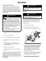
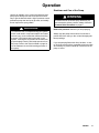
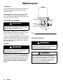
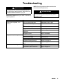
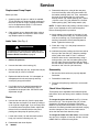
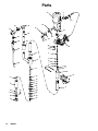
1
Instructions
President 10:1 Ratio
Air Spray System
For transfer or supply of compatible fluids.
With Evenflor Automatic Pressure Control
Model 954088, Series A
180 psi (12 bar, 1.2 MPa) Maximum Working Pressure (Air Input)
Related Manuals
Evenflor Automatic Pressure Control . . 306479
President Air Motor . . . . . . . . . . . . . . . . . . 306982
GRACO INC. P.O. BOX 1441 MINNEAPOLIS, MN 55440- 1441
Copyright 2003, Graco Inc. is registered to I.S. EN ISO 9001
309489D
Table of Contents
Warnings . . . . . . . . . . . . . . . . . . . . . . . . . . . . . . . . . . . . . . 2
Installation . . . . . . . . . . . . . . . . . . . . . . . . . . . . . . . . . . . . . 5
Operation . . . . . . . . . . . . . . . . . . . . . . . . . . . . . . . . . . . . . 8
Maintenance . . . . . . . . . . . . . . . . . . . . . . . . . . . . . . . . . . 10
Troubleshooting . . . . . . . . . . . . . . . . . . . . . . . . . . . . . . . 11
Displacement Pump Repair . . . . . . . . . . . . . . . . . . . . . 12
Check Valve Adjustment . . . . . . . . . . . . . . . . . . . . . . . 12
Parts Lists and Drawings
Model 954088 . . . . . . . . . . . . . . . . . . . . . . . . . . . . . .
Technical Data . . . . . . . . . . . . . . . . . . . . . . . . . . . . . . . .
Dimensions . . . . . . . . . . . . . . . . . . . . . . . . . . . . . . . . . . .
Warranty . . . . . . . . . . . . . . . . . . . . . . . . . . . . . . . . . . . . .
Graco Information . . . . . . . . . . . . . . . . . . . . . . . . . . . . .
14
16
17
20
20
Symbols
Warning Symbol
Caution Symbol
WARNING
CAUTION
This symbol alerts you to the possibility of serious
injury or death if you do not follow the instructions.
This symbol alerts you to the possibility of damage to
or destruction of equipment if you do not follow the
instructions.
WARNING
EQUIPMENT MISUSE HAZARD
Equipment misuse can cause the equipment to rupture or malfunction and result in serious injury.
D This equipment is for professional use only.
D Read all instruction manuals, tags, and labels before operating the equipment.
D Use the equipment only for its intended purpose. If you are not sure, call your Graco distributor.
D Do not alter or modify this equipment.
D Check equipment daily. Repair or replace worn or damaged parts immediately.
D Do not exceed the maximum working pressure stated on the equipment or in the Technical Data
for your equipment. Do not exceed the maximum working pressure of the lowest rated component
in your system.
D Use fluids and solvents which are compatible with the equipment wetted parts. Refer to the Technical Data section of all equipment manuals. Read the fluid and solvent manufacturer’s warnings.
D Handle hoses carefully. Do not pull on hoses to move equipment.
D Route hoses away from traffic areas, sharp edges, moving parts, and hot surfaces. Do not expose
Graco hoses to temperatures above 66_C (150_F) or below --40_C (--40_F).
D Wear hearing protection when operating this equipment.
D Do not move or lift pressurized equipment.
D Comply with all applicable local, state, and national fire, electrical, and safety regulations.
2
309489
WARNING
INJECTION HAZARD
Spray from the gun, leaks or ruptured components can inject fluid into your body and cause extremely
serious injury, including the need for amputation. Fluid splashed in the eyes or on the skin can also
cause serious injury.
D Fluid injected into the skin is a serious injury. The injury may look like just a cut, but it is a serious
injury. Get immediate medical attention.
D Do not point the gun at anyone or at any part of the body.
D Do not put your hand or fingers over the spray tip.
D Do not stop or deflect leaks with your hand, body, glove or rag.
D Do not “blow back” fluid; this is not an air spray system.
D Always have the tip guard and the trigger guard on the gun when spraying.
D Check the gun diffuser operation weekly. Refer to the gun manual.
D Be sure the gun trigger safety operates before spraying.
D Lock the gun trigger safety when you stop spraying.
D Follow the Pressure Relief Procedure on page 8 if the spray tip clogs and before cleaning,
checking or servicing the equipment.
D Tighten all fluid connections before operating the equipment.
D Check the hoses, tubes, and couplings daily. Replace worn, damaged, or loose parts immediately.
Permanently coupled hoses cannot be repaired; replace the entire hose.
MOVING PARTS HAZARD
Moving parts can pinch or amputate your fingers.
D Keep clear of all moving parts when starting or operating the pump.
D Before checking or servicing the equipment, follow the Pressure Relief Procedure on page 8 to
prevent the equipment from starting unexpectedly.
309489
3
WARNING
FIRE AND EXPLOSION HAZARD
Improper grounding, poor ventilation, open flames or sparks can cause a hazardous condition and result in a fire or explosion and serious injury.
D Ground the equipment and the object being sprayed. Refer to Grounding on page 5.
D If there is any static sparking or you feel an electric shock while using this equipment, stop spraying immediately. Do not use the equipment until you identify and correct the problem.
D Provide fresh air ventilation to avoid the buildup of flammable fumes from solvents or the fluid
being sprayed.
D Keep the spray area free of debris, including solvent, rags, and gasoline.
D Before operating this equipment, electrically disconnect all equipment in the spray area.
D Before operating this equipment, extinguish all open flames or pilot lights in the spray area.
D Do not smoke in the spray area.
D Do not turn on or off any light switch in the spray area while spraying or while operating if fumes
are present.
D Do not operate a gasoline engine in the spray area.
D Never use 1,1,1--trichloroethane, methylene chloride, other halogenated hydrocarbon solvents, or
fluids containing such solvents in this equipment. Such use could result in a serious chemical
reaction, with the possibility of explosion, which could cause death, serious injury, and/or substantial property damage.
Consult your fluid suppliers to ensure that fluids being used are compatible with aluminum and zinc
parts.
TOXIC FLUID HAZARD
Hazardous fluid or toxic fumes can cause serious injury or death if splashed in the eyes or on the skin,
inhaled, or swallowed.
D Know the specific hazards of the fluid you are using.
D Store hazardous fluid in an approved container. Dispose of hazardous fluid according to all local,
state and national guidelines.
D Always wear protective eyewear, gloves, clothing and respirator as recommended by the fluid and
solvent manufacturer.
4
309489
Installation
General Information
NOTE: Reference numbers and letters in parentheses
refer to callouts in the Figs. and parts drawing.
NOTE: Always use Genuine Graco Parts and Accessories, available from your Graco distributor.
Grounding
WARNING
FIRE AND EXPLOSION HAZARD
Before operating the pump, ground the
system as explained below. Also read
the section FIRE OR EXPLOSION HAZARD on page 4.
4. Spray gun or dispensing valve: ground through
connection to a grounded fluid hose and pump.
5. Fluid supply container: follow your local code.
6. Object being sprayed: follow your local code.
7. Solvent pails used when flushing: follow your local
code. Use only conductive metal pails, placed on a
grounded surface. Do not place the pail on a
nonconductive surface, such as paper or cardboard, which interrupts the grounding continuity.
8. To maintain grounding continuity when flushing or
relieving pressure, hold a metal part of the spray
gun firmly to the side of a grounded metal pail,
then trigger the gun.
1. Pump: use a ground wire and clamp as shown in
Fig. 1. Loosen the grounding lug locknut (W) and
washer (X). Insert one end of a 12 ga (1.5 mm@)
minimum ground wire (Y) into the slot in lug (Z)
and tighten the locknut securely. Connect the other
end of the wire to a true earth ground. Order part
number 222011 Grounding Clamp and Wire.
X
Z
Y
2. Air and fluid hoses: use only conductive hoses.
3. Air compressor: follow manufacturer’s recommendations.
Fig. 1
W
309489
0720
5
Installation
NOTE: Reference numbers and letters in parentheses
in the text refer to callouts in the figure illustrations and
the parts drawing.
The Typical installation shown on page 7 is only a
guide to electing and installing required and optional
accessories. For assistance in designing a system to
suit your needs, contact your Graco representative.
Mount the pump to suit the type of installation planned.
The pump dimensions and mounting hole layout are
shown on page 17.
Pail and Drum Length Pumps
Install the pump in the drum or pail, using a suitable
cover, bung adapter, or mounting clamp. The pump
must be 1/2 in. (13 mm) off the bottom of the pail or
drum.
The pump has a by--pass tube, route the tube back to
the supply container.
NOTE: In a closed-head drum, be sure to loosen the
vent plug in the drum cover to prevent formation of a
vacuum.
WARNING
An accessory is required in your system: a bleedtype master air valve (A). This accessory helps
reduce the risk of serious injury including injection,
splashing in the eyes, and injury from moving parts
if you are adjusting or repairing the pump.
The bleed-type master air valve relieves air trapped
between this valve and the pump after the air
regulator is shut off. Trapped air can cause the
pump to cycle unexpectedly. Locate the valve close
to the pump.
The fluid drain valve (part of the Evenflor air
regulator installed on pump) assists in relieving
fluid pressure in the displacement pump, hose, and
gun; triggering the gun to relieve pressure may not
be sufficient.
6
309489
Evenflor Automatic Pressure Control
An Evenflor air regulator installed on the pump has a
Relax-A-Valve. This regulator prevents initial surging of
non-atomized fluid when the gun is triggered. Air
pressure in the pump is relieved automatically each
time the gun trigger is released. When used with a
Relax-A-Valve set in the automatic position, fluid
pressure is relieved automatically also. Refer to the
Evenflor Automatic Pressure Manual for additional
information.
All Pumps
Install the air line accessories in the approximate order
shown in the Typical Installation drawing. A pump
runaway valve (B) senses when the pump is running
too fast and shuts off the air supply to the motor. For
automatic air motor lubrication, install an air line lubricator (D). (For manual lubrication, see Maintenance on
page 10). Install the bleed-type master air valve (A)
within easy reach of the pump. Install an air regulator
(E) to control air to the motor and pump speed. An air
line filter (C) removes harmful dirt and moisture from
your compressed air supply.
Be sure that the air supply hose is properly grounded,
and is at least 1.2 in. (13 mm) ID in order to supply an
adequate volume of air to the motor.
Connect a suitable grounded fluid hose and spray gun
or dispensing valve to the pump’s 3/4 in. npt outlet.
Installation
Typical Installation
L
KEY
A Bleed-Type Master Air Valve
B Pump Runaway Valve
C Air Line Filter
D Air Line Lubricator
E Pump Air Regulator
H Drain Valve (part of 38, Evenflor Valve)
J Pump Ground Wire
K Grounded Fluid Hose
L Grounded Air Hose
M Evenflor Control Knob (rear of valve)
38 Evenflor Valve
52 By--pass Tube
B
D
E
J
A
C
38
H
K
52
EvenfloR Air Regulator
1/2” Minimum
M
ti3003a7
309489
7
Operation
Pressure Relief Procedure
With the Evenflor control, its bypass valve, and the
pump Relax-A-Valve properly set, fluid pressure is
relieved from the pump and hose each time you release the gun trigger. Always engage the gun trigger
safety when you stop spraying. To relieve air pressure,
close the Evenflo regulators and open the bleed-type
master air valve.
WARNING
INJECTION HAZARD
If you suspect that the Evenflor system
is not properly set, or that pressure is
not fully relieved, the system pressure
must be manually relieved to prevent the system
from starting or spraying accidentally. Fluid under
high pressure can be injected through the skin and
cause serious injury. To reduce the risk of an injury
from injection, splashing fluid, or moving parts, follow the Pressure Relief Procedure whenever you:
D
D
D
D
are instructed to relieve the pressure,
stop spraying,
check or service any of the system equipment,
or install or clean the spray tips.
WARNING
Never operate the pump with the air motor plate
removed. Moving parts in the piston can pinch or
amputate fingers.
Startup
WARNING
To reduce the risk of serious injury whenever you
are instructed to relieve pressure, always follow the
Pressure Relief Procedure on page 8.
The pump was tested in oil, and some oil was left in
the pump to protect it from corrosion. if the oil will
contaminate the fluid your are pumping, flush it out.
To Start the Pump:
1. Close the fluid drain valve (H).
2. Open the bleed--type master air valve (A).
3. Open the EvenfloR control knob (M) four full turns.
A
1. Engage the spray gun or dispensing valve safety
latch.
M
B
2. Close the pump air regulator.
3. Close the master bleed-type air valve (required).
4. Disengage the gun or dispensing valve safety
latch.
5. Hold a metal part of the gun/valve firmly to a
grounded metal waste container and trigger to
relieve fluid pressure.
6. Engage the safety latch again.
7. Insure the Relax-A-Valve is set in the automatic
position.
If you suspect that the spray tip or hose is completely
clogged, or that pressure has not been fully relieved
after following the steps above, very slowly loosen the
tip guard retaining nut or hose end coupling and relieve
pressure gradually, then loosen completely. Now clear
the tip or hose.
8
309489
Fig. 2
6412B
4. Holding a metal part of the applicator firmly against
the side of a grounded metal pail, hold the trigger
open while slowly opening the air regulator (B).
While the applicator air is on, slowly open the
pump air regulator (A). If the pump does not
operate, release the trigger and close the control
valve (M) a quarter turn.
5. Repeat this process until the pump operates when
the applicator is triggered. Trigger the applicator
until flushing of the oil is complete.
6. Gradually adjust the pump and applicator air
pressure as needed during normal operation.
Operation
Shutdown and Care of the Pump
Use the air regulator (A) to control fluid pressure and
pump speed. Always use the lowest pressure necessary to get the desired results. Higher pressures cause
premature pump wear and spray tip wear, and usually
do not improve the spray pattern.
WARNING
To reduce the risk of overpressurizing your system,
which could result in component rupture and cause
serious injury, never exceed the maximum working
pressure of the lowest rated component in your
system. Lowering the air pressure to the motor will
proportionately lower the fluid outlet pressure from
the pump. Refer to the Technical Data on page 16
for the maximum air and fluid working pressure of
this pump.
WARNING
To reduce the risk of serious injury whenever you
are instructed to relieve pressure, always follow the
Pressure Relief Procedure on page 8.
Relieve the pressure whenever you stop spraying.
Always stop the pump at the bottom of its stroke to
prevent fluid from drying on the rod and damaging the
throat packings.
If you are pumping fluid which dries, hardens, or sets
up, flush the system with a compatible solvent as often
as necessary to prevent a build up of dried fluid in the
pump or hoses.
309489
9
Maintenance
Lubrication
If your system includes an automatic air line lubricator,
adjust the lubricator as instructed in the separate
instruction manual.
For manual lubrication, each day, remove the air inlet
hose and place 12 to 15 drops of high quality, light
motor oil in the inlet. Reattach the hose and turn on the
air to blow the oil into the motor.
Throat Packing Adjustment
WARNING
To reduce the risk of serious injury whenever you
are instructed to relieve pressure, always follow the
Pressure Relief Procedure on page 8.
Once a week, or after each 40 hours of operation,
check the tightness of the throat packing nut. It should
be tight enough to stop leakage, but no tighter.
To check, first relieve the pressure. Then, remove the
identification plate (M) from the motor. Using a spanner
wrench or a 0.22 in (5.6 mm) diameter rod, adjust the
nut. Reinstall the identification plate before operating
the pump. See Fig. 3.
Flushing
WARNING
To reduce the risk of serious injury whenever you
are instructed to relieve pressure, always follow the
Pressure Relief Procedure on page 8.
To reduce the risk of injection injury, static sparking, or
splashing in the eyes or on the skin, relieve the pressure. Then, remove the spray tip (spray guns or spray
valves only) before flushing. Hold a metal part of the
gun/valve firmly to the side of a grounded metal pail
and use the lowest possible fluid pressure during
flushing.
10
309489
M
Packing
Nut
Leather
Throat
Packings
06701
Fig. 3
Corrosion Protection
WARNING
To reduce the risk of serious injury whenever you
are instructed to relieve pressure, always follow the
Pressure Relief Procedure on page 8.
CAUTION
Water, or even moist air, can cause your pump to
corrode. To help prevent corrosion, never leave the
pump filled with water-based fluid or air. After normal
flushing, flush the pump again with mineral spirits or
oil-based solvent, and relieve the pressure. This
leaves the mineral spirits in the pump.
Troubleshooting
WARNING
To reduce the risk of serious injury whenever you
are instructed to relieve pressure, always follow the
Pressure Relief Procedure on page 8.
Relieve the pressure before you check or service any
system equipment.
NOTE: Check all possible problems and solutions
before disassembling the pump.
WARNING
Never operate the pump with the air motor plate
removed. Moving parts in the piston can pinch or
amputate fingers.
Problem
Cause
Solution
Pump
p does not operate,
p
, or no
fluid flow
Loose or broken pump parts
Disassemble, check, repair
Restricted line or inadequate air supply
Clear, increase
Exhausted fluid supply
Refill and prime
Clogged fluid hoses
Clean, or replace
Fluid intake or piston valves need
adjustment
Adjust, see page 12
Damaged air motor
Repair; see 306982
Insufficient air supply
Increase
Exhausted fluid supply
Refill and prime
Obstructed gun or dispensing valve
Clear
Damaged fluid pump packings
Replace, see page 12
Held open or worn piston or intake
valve
Repair; see page 12
Exhausted fluid supply
Refill and prime
Fluid intake or piston valve worn
Repair; see page 12
Pump
p operates,
p
, but output
p is low
Erratic or accelerated operation
p
309489
11
Service
Displacement Pump Repair
Before you start:
1. A packing repair kit, part no. 946761 is available.
This kit includes two glands and eight packings for
the motor as well as o-rings, packings, and washers for the displacement pump. For the best results use all the parts in the kit.
2. Clean all parts as you disassemble them, using a
compatible solvent, and inspect for wear or damage. Replace parts as necessary.
Intake Valve (See Fig. 4)
WARNING
To reduce the risk of serious injury whenever you
are instructed to relieve pressure, always follow the
Pressure Relief Procedure on page 8.
1. Relieve the pressure.
2. Unscrew the intake valve housing (27).
3. Remove the ball stop pin (24). Inspect the ball (25)
and seat (23) for nicks or scratches.
4. Replace the ball and/or seat if it is damaged, as
damaged parts do not seal properly and may
cause poor pump performance.
5. If no further service is needed reassemble the
intake valve. Be sure the ball stop pin (24) is
reinstalled in the proper holes. See Check Valve
Adjustment at right.
Piston
9. Reassemble the piston, using all the new parts
from the kit and any other new parts needed. Oil
the leather packings (20*) first. Then, reassemble
the parts on the piston seat (21) in this order;
backup washer (18), leather packing (20*), spacer
(19) with a new o-ring (22) installed on it, another
leather packing (20*), and backup washer (18*).
NOTE: To replace the throat packings, follow the steps
given in your separate air motor manual supplied,
before continuing with this procedure.
10. Apply sealant to the threads of the seat (21) and
screw onto the piston body (16). Screw the piston
onto the connecting rod (14) and adjust the ball
travel as instructed in Check Valve Adjustment,
below. Tighten the locknut (15).
11. Check the o-ring (11) in the pump base and replace it if necessary.
12. Lubricate the piston packings and the inner wall at
the top of the riser tube (13). Wrap the packings
with a guide collar made of 1/64 in. maximum
thickness shim stock or metal sheeting. Using a
turning motion, work the first leather packing into
the riser tube. Remove the guide collar and push
the riser tube up and screw it into the base. Torque
the tube to 100--150 ft-lb (135--204 NSm).
Reassembly
1. Be sure the check valves are properly adjusted.
See below.
2. Reinstall the intake valve.
3. Reconnect the pump’s ground wire to a true earth
ground.
Check Valve Adjustment
These pumps have adjustable fluid intake and piston
ball checks, which are factory-set for medium viscosity
fluids.
6. Unscrew the riser tube (13) from the pump base.
Clean the tube and inspect it for wear by holding it
up to a light at a slight angle. If you see wavy lines
or scratches where the piston travels, replace the
tube as it will not seal well with the new piston
packings and the pump will perform poorly.
To change the piston ball travel (see Fig. 5) loosen
the lock-nut (15). Turn the piston body (16) counterclockwise to increase and clockwise to decrease.
Medium viscosity fluids should have a 3/16 in (5 mm)
ball travel. Decreasing the ball travel minimizes surging
at stroke changeover, but too short a ball travel restricts the flow and slows down the pump.
7. Loosen the locknut (15) and unscrew the piston
body (16) from the connecting rod (14).
To change the intake valve ball travel, move the ball
stop pin (24) to a higher or lower set of holes. Use the
middle holes for medium viscosity fluids.
8. Disassemble and clean all parts.
12
309489
1
43
Torque to 100--150 ft-lb
(136--204 NSm)
2
50
30
42
51
31
47
49
29
3*
48
46
34
36
35
33
32
45
1
44
53
10*
12
52
14
38
4
6
*8
7
*8
39
9
28
1
16
17
20
18*
19
22*
18*
20
13
25
*23
37
15
*11
24
26
5
21
27
Fig. 4
2
8
3/16” Piston
Ball Travel
19
Fig. 5
4
15
06703
309489
13
Parts
43
2
50
30
42
51
31
47
49
29
3*
48
46
34
36
35
33
32
45
1
44
53
10*
12
52
14
38
4
6
*8
7
*8
39
9
28
13
25
*23
26
27
14
309489
37
15
*11
24
16
17
20
18*
19
22*
18*
20
21
5
Parts
Model 954088, Series A
Includes items 1--53
Ref.
No.
Part No.
Description
1
2
3*
4
5
6
7
8*
9
10*
11*
12
13
14
15
16
17
18*
19
20
21
22*
23*
24
25
26
27
28
100016
621201
510636
620850
620832
620842
620841
510476
620840
510473
510472
946669
620833
620849
101960
620848
101917
510475
620837
620836
620831
154662
166238
162947
101968
186991
164630
621203
WASHER, lock
STUD, clamp
PIN, spring, str
ROD, connecting
CYLINDER, pump, displacement
STUD, throat, packing
PACKING, spacer, throat
PACKING, cup
PACKING, nut, throat
PACKING, o--ring
PACKING, o--ring
HOUSING, outlet pump
CYLINDER, pump, disp, 10:1 pres
ROD, connecting
NUT
HOUSING, valve
BALL, bearing
PACKING, cup
SPACER, cup
WASHER, piston, packing
SEAT, valve
PACKING, o--ring
PACKING, o--ring
PIN, straight, headless
BALL, bearing
HOUSING, valve, intake
RING, locking
CLAMP, tube
Qty.
2
1
1
1
1
1
1
2
1
1
1
1
1
1
1
1
1
2
1
2
1
1
1
1
1
1
1
1
Ref.
No.
Part No.
Description
29
30
31
32
33
34
35
36
37
38
620835
621201
946670
104137
102790
100676
100020
510787
203156
202844
39
42
43
620985
510786
206078
44
45
46
47
48
49
50
51
52
53
100022
502682
237469
504134
500084
101754
158256
504704
190339
112790
FITTING, nipple, pipe
STUD, clamp
CLAMP, pipe
SCREW, binder, 10--24 x 3/8
SCREW, machine, pan hd
NUT
WASHER, lock
FITTING, coupling, pipe
CLAMP, pump
PRESSURE CONTROL,
automatic, Evenflor
See manual 306479 for parts
PACKING, washer, throat
FITTING, elbow, pipe
AIR MOTOR, president
See manual 306982 for parts
SCREW, cap, hex hd
WASHER, flat, cs
VALVE, ball, heavy duty
FITTING, tee, pipe
BUSHING, hex hd
PLUG, pipe
UNION, swivel
FITTING, nipple, hex
TUBE, by--pass
CONNECTOR, tube
Qty.
1
1
1
1
1
1
1
1
1
1
1
1
1
2
2
1
1
1
1
1
1
1
1
* Parts included in Repair Kit 946761
309489
15
Technical Data
Fluid pressure ratio . . . . . . . . . . . . . . . . . . . . . . . . . . . . . . . . . . . . . . . . . . . . . . . . . . . . . . . . . . . . . . . . . . . . . . . . . . . . . . . 10:1
Air pressure operating range . . . . . . . . . . . . . . . . . . . . . . . . . . . . . . . . . . . . . . . . . . . . . . . . . . . . . . . . 40--180 psi (3--12 bar)
Maximum fluid working pressure . . . . . . . . . . . . . . . . . . . . . . . . . . . . . . . . . . . . . . . . . . . . . . . . . . . . . . . . 1800 psi (124 bar)
Maximum recommended pump speed . . . . . . . . . . . . . . . . . . . . . . . . . . . . . . . . . . . . . . . . . . . . . . . . . . . . 60 cycles/minute
Delivery (continuous duty) . . . . . . . . . . . . . . . . . . . . . . . . . . . . . . . . . . . . . . . . . . . . . . . . . . . . . . . . . . . . 3 gpm (12 liter/min)
Delivery (intermittent duty) . . . . . . . . . . . . . . . . . . . . . . . . . . . . . . . . . . . . . . . . . . . . . . . . . . . . . . . . . . . . 6 gpm (25 liter/min)
Cycles per gallon (liter) . . . . . . . . . . . . . . . . . . . . . . . . . . . . . . . . . . . . . . . . . . . . . . . . . . . . . . . . . . . . . . . . . . . . . . . . . . . 20 (6)
Air motor effective diameter . . . . . . . . . . . . . . . . . . . . . . . . . . . . . . . . . . . . . . . . . . . . . . . . . . . . . . . . . . . . 4--1/4 in. (108 mm)
Pump stroke . . . . . . . . . . . . . . . . . . . . . . . . . . . . . . . . . . . . . . . . . . . . . . . . . . . . . . . . . . . . . . . . . . . . . . . . . . . . 4 in. (100 mm)
Air consumption . . . . . . . . . . . . . . . . . . . . . . . . . . . . . Approx. 13 CFM per gallon (6m#/hr/liter) of fluid at 100 psi (7 bar)
Wetted parts . . . . . . . . . . . . . . . . . . . . . . . . . . . . . . . . . . . . . . . . . . . . . . . . . . . . . Steel, Aluminum, Brass, Leather, Buna-N
16
309489
Dimensions
14--1/2”
(368.3 mm)
6--3/4”
(171.4 mm)
1--1/4”
(31.8 mm)
1”
(25.4 mm)
3/8 npt 11/16”
(17.5 mm) OD
Bottom View
6--1/2”
(165.1 mm)
45_
45_
2--3/32”
(53.2 mm)
Four 1/4”--20 Holes
on a 4--1/4” (108 mm)
Dia. Bolt Circle
309489
17
Dimensions
Model 954088, Series A
Weight: 40 lb (18 Kg)
4” (101.6 mm)
3/8 npsm
39--1/4”
(997 mm)
53--3/4”
(1365.3 mm)
1
2--1/4” (47.2 mm)
18
309489
1
Height of 55 gallon
drum 34--3/4 (883 mm)
Notes
309489
19
Graco Standard Warranty
Graco warrants all equipment manufactured by Graco and bearing its name to be free from defects in material and workmanship on the
date of sale to the original purchaser for use. With the exception of any special, extended, or limited warranty published by Graco,
Graco will, for a period of twelve months from the date of sale, repair or replace any part of the equipment determined by Graco to be
defective. This warranty applies only when the equipment is installed, operated and maintained in accordance with Graco’s written
recommendations.
This warranty does not cover, and Graco shall not be liable for general wear and tear, or any malfunction, damage or wear caused by
faulty installation, misapplication, abrasion, corrosion, inadequate or improper maintenance, negligence, accident, tampering, or substitution of non--Graco component parts. Nor shall Graco be liable for malfunction, damage or wear caused by the incompatibility of
Graco equipment with structures, accessories, equipment or materials not supplied by Graco, or the improper design, manufacture,
installation, operation or maintenance of structures, accessories, equipment or materials not supplied by Graco.
This warranty is conditioned upon the prepaid return of the equipment claimed to be defective to an authorized Graco distributor for
verification of the claimed defect. If the claimed defect is verified, Graco will repair or replace free of charge any defective parts. The
equipment will be returned to the original purchaser transportation prepaid. If inspection of the equipment does not disclose any defect
in material or workmanship, repairs will be made at a reasonable charge, which charges may include the costs of parts, labor, and
transportation.
THIS WARRANTY IS EXCLUSIVE, AND IS IN LIEU OF ANY OTHER WARRANTIES, EXPRESS OR IMPLIED, INCLUDING BUT
NOT LIMITED TO WARRANTY OF MERCHANTABILITY OR WARRANTY OF FITNESS FOR A PARTICULAR PURPOSE.
Graco’s sole obligation and buyer’s sole remedy for any breach of warranty shall be as set forth above. The buyer agrees that no other
remedy (including, but not limited to, incidental or consequential damages for lost profits, lost sales, injury to person or property, or any
other incidental or consequential loss) shall be available. Any action for breach of warranty must be brought within two (2) years of the
date of sale.
Graco makes no warranty, and disclaims all implied warranties of merchantability and fitness for a particular purpose in connection
with accessories, equipment, materials or components sold but not manufactured by Graco. These items sold, but not manufactured
by Graco (such as electric motors, switches, hose, etc.), are subject to the warranty, if any, of their manufacturer. Graco will provide
purchaser with reasonable assistance in making any claim for breach of these warranties.
In no event will Graco be liable for indirect, incidental, special or consequential damages resulting from Graco supplying equipment
hereunder, or the furnishing, performance, or use of any products or other goods sold hereto, whether due to a breach of contract,
breach of warranty, the negligence of Graco, or otherwise.
FOR GRACO CANADA CUSTOMERS
The parties acknowledge that they have required that the present document, as well as all documents, notices and legal proceedings
entered into, given or instituted pursuant hereto or relating directly or indirectly hereto, be drawn up in English. Les parties reconnaissent avoir convenu que la rédaction du présente document sera en Anglais, ainsi que tous documents, avis et procédures judiciaires
exécutés, donnés ou intentés à la suite de ou en rapport, directement ou indirectement, avec les procedures concernées.
Graco Information
TO PLACE AN ORDER, contact your Graco distributor, or call one of the following numbers
to identify the distributor closest to you:
1--800--328--0211 Toll Free
612--623--6921
612--378--3505 Fax
All written and visual data contained in this document reflects the latest product information available at the time of publication.
Graco reserves the right to make changes at any time without notice.
MM 309489
Graco Headquarters: Minneapolis
International Offices: Belgium, Korea, China, Japan
GRACO INC.
P.O. BOX 1441
MINNEAPOLIS, MN 55440--1441
www.graco.com
PRINTED IN USA 309489 11/2004 Rev. 10/2008
20
309489