1
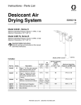
Instructions - Parts List
Membrane Air Drying
System
309920D
EN
Model 234418, Series C
Maximum Working Pressure 160 psi (1.1 MPa,
11 bar)
Maximum Temperature 150° F (65° C)
Important Safety Instructions
Read all warnings and instructions in this manual.
Save these instructions
ti22159a
Includes:
Air Inlet
npt(f)
Air
Outlet
npt(f)
Air Flow
Capacity
at 100 psi
(0.7 MPa, 7 bar)
Maximum
Operating
Pressure
Part No.
Series
Description
234402
B
Stage 1 - Air Filter with auto drain
Removes water and contaminants down
to 3 microns.
1/2”
1/2”
100 CFM
175 psi
(1.2 MPa, 12 bar)
234397
B
Stage 2 - Coalescer with auto drain
Removes oil and sub-micronic particles
down to 1 micron.
1/2”
1/2”
83 CFM
175 psi
(1.2 MPa, 12 bar)
118560
A
Stage 3 - Membrane Air Dryer
Removes uncondensed moisture.
1/2”
1/2”
30 CFM
175 psi
(1.2 MPa, 12 bar)
234394
A
Self Relieving Air Regulator
3/8”
1/4”
100 CFM
288798
A
Shut-off Valve
160 psi
1.1 MPa, 11 bar)
175 psi
(1.2 MPa, 12 bar)
Installation
Installation
1. Before installing air line components, blow out the
pipe line to remove debris. Be sure air to the regulator is clean. Erratic operation or loss of regulation is
usually caused by dirt in the regulator.
2. Install the Air Drying System as close as possible to
the equipment it serves.
3. Install air shut-off valve 288798 upstream from the
air system to isolate it for service.
4. Install system so air flows through filters in the direction noted on top of filter.
5. A minimum 1/2” npt piping is recommended. Avoid
using too many fittings, couplings, etc., which will
restrict air flow.
Shop Air Piping Layout
Main Air Line
3/4” (19 mm) minimum
1-1/4” (32 mm) optimum
1/2” (13
mm) drops
Slope
s
Recom down and a
w
drop in mended 4” ay
(1
50’ (1
5.24 m 17 mm)
) galva
nized
Air Control unit
or Air Filter
Membrane air
drying system
8
6
4
1
6
8
2
1
2
1
4
Ball Valve
1
1
Compressor
Coalescer
Air
Filter
Main Air
Shut-off Valve
Drain
Leg
OR
Desiccant air
drying system
8
4
6
1
8
2
1
2
1
4
6
1
1
Flexible hose
between compressor
and stand pipe
15-2
0
ft. ( 4
.6 - 6
Drain Valve
.1 m
)
DESICCANT
NORMA
SATURA
TED
¨
•
•
2
Main Air Line stand pipe should not be smaller than compressor outlet size.
A minimum of 25 ft. (7.62 m) from compressor to first filter outlet is required to cool air [50 ft. (15.24 m) optimum]
309920D
Shop Air Piping Layout
Minimum Pipe Size Recommendations
Compressor
Main Air Line
Size
Capacity
Length
Size
1-1/2 - 2 HP
6 - 9 CFM
any
3/4” (19 mm)
3 - 5 HP
12 - 20 CFM
Up to 200 ft. (61 m)
3/4” (19 mm)
Over 200 ft. (61 m)
1” (25.4 mm))
5 - 10 HP
20 - 40 CFM
10 - 15 HP
40 - 60 CFM
Up to 100 ft. (30.5)
3/4” (19 mm)
Over100-200ft.(30.5-61m)
1” (25.4 mm)
Over 200 ft. (61 m)
1-1/4” (31.8 mm)
Up to 100 ft. (30.5)
3/4” (19 mm)
Over100-200ft.(30.5-61m)
1-1/4” (31.8)
Over 200 ft. (61 m)
1-1/2” (38.1)
Air Pressure Drop Through Hose, by hose length and ID
psi (Kpa, bar)
Air Hose Inside
Diameter
4 ft.
(1.22 m)
10 ft.
(3.05 m)
15 ft.
(4.6 m)
20 ft.
(6.1 m)
25 ft.
(7.62 m)
50 ft.
(15.24 m)
1/4 in. (6.4 mm)
40 psi (276 kPa, 2.8 bar)
50 psi (345 kPa, 3.4 bar)
60 psi (414 kPa, 4.1 bar)
70 psi (483 kPa, 4.8 bar)
80 psi (552 kPa, 5.5 bar)
90 psi (621 kPa, 6.2 bar)
9.5 (66, .7)
8 (55, .6)
6 (41, .4)
12 (83, .8)
10 (69, .7)
7.5 (52, .5)
14.5 (100, .1)
12.5 (86, .9)
9 (62, .6)
17 (117, 1.2)
14.5 (100, 1)
10.75 (74, .7)
12.25 (84, .8) 16.5(114,1.1) 19.5 (134, 1.3)
18.75 (129, 1.3) 22 (152, 1.5)
14 (97, 1)
11 (76, .8)
12.75 (88, 0.9) 24 (165, 1.7)
14 (97, 1)
28 (193, 1.9)
16 (110, 1.1)
16.75(115,1.2) 19 (131, 1.3)
31 (214, 2.1)
19.5 (134, 1.3) 22.5 (155, 1.6) 34 (234, 2.3)
22.5 (155, 1.6) 25.5 (176, 1.8) 37 (255, 2.6)
25.25 (172, 1.7) 29 (200, 2)
39.5 (169, 2.7)
5/16 in. (7.9 mm)
40 psi (276 kPa, 2.8 bar)
50 psi (345 kPa, 3.4 bar)
60 psi (414 kPa, 4.1 bar)
70 psi (483 kPa, 4.8 bar)
80 psi (552 kPa, 5.5 bar)
90 psi (621 kPa, 6.2 bar)
309920D
2.25 (16, .2)
3 (21, .2)
3.75 (26, .3)
4.5(31, .3)
5.5 (38, .4)
6.5 (45, .4)
2.75 (19, .2)
3.5 (24, .2)
4.5 (31, .3)
5.25 (36, .4)
6.25 (43, .4)
7.5 (52, .5)
3.25 (22, .2)
4 (28, .3)
5 (34, .3)
6 (41, .4)
7 (48, .5)
8.5 (59, .6)
3.5 (24, .2)
4.5 (31, .3)
5.5 (38, .4)
6.75 (47, .5)
8 (55, .6)
9.5 (66, .7)
4 (28, .3)
5 (34, .3)
6 (41, .4)
7.25 (50, .5)
8.75 (60, .6)
10.5 (72, .7)
8.5 (59, .6)
10 (69, .7)
11.5 (79, .8)
13 (90, .9)
14.5 (100, 1)
16 (110, 1.1)
3
Operation
Operation
WARNING
Do not exceed the Maximum Incoming Air Pressure of
the equipment. Over pressurizing can cause component rupture and serious injury.
1. Attach air hose(s) to air regulator outlet valve
289165.
2. Open main shut-off valve 288798.
3. Turn the T-hand adjusting screw in or out to adjust
regulator to desired setting.
4. Open outlet valve 289165 to supply air to spray
guns or tool.
5. With air flowing, readjust air pressure regulator if
necessary.
pressure drop across the element reaches 10-12 psi
(69-83 kPa, 0.7-0.8 bar), the red indicator will be in full
view, and the element should be replaced. Failure to
replace the element when the pressure drop exceeds 10
psi (69 kPa, 0.7 bar) will affect your air quality and tool
efficiency.
Automatic Drain
The automatic drain is equipped with a float actuated
device which automatically ejects liquid contaminates
under pressure.
Parts
Part No.
234402
234397
6. Turn off unit when not in use. Follow Pressure
Relief Procedure, page 5.
Coalescer Pressure Drop Indicator
118560
234394
289165
288798
Description
Air Filter with auto drain; see manual
309919 for parts information
Coalescer with auto drain; see manual
309919 for parts information
Membrane Air Dryer
Air Regulator; see manual 309924 for
parts information
Shut-off Valve
Shut-off Valve
The differential pressure drop indicator provides early
detection of a clogged coalescing filter element. As the
filter element becomes clogged, the red indicator starts
to rise while air is flowing through the unit. When the
288798
118560
234402
234397
289165
234394
4
ti22160a
309920D
How Membrane Air Dryer Works
How Membrane Air Dryer Works
Wet air enters
membrane module
Water vapor purges
Clean, dry air
exits module
Water vapor permeates through
hollow membrane fibers
Pressure Relief Procedure
WARNING
To avoid injury, relieve air and fluid pressure before
checking, cleaning, or repairing the equipment.
The following is a basic pressure relief procedure. Be
sure to follow the specific pressure relief procedure in
your spray gun and/or fluid supply equipment manuals.
1. Close the main air shut-off valve.
2. Trigger the gun or dispense valve and open any
drain valves to relieve pressure.
Maintenance
•
•
309920D
Relieve the pressure before cleaning, checking
or repairing equipment. Follow Pressure
Relief Procedure, above.
Check system at least once per shift to ensure
proper drainage.
Air Filter with Auto Drain 234402, Series B
To maintain maximum filtering efficiency and avoid
excessive pressure drop, the filter must be kept clean.
See Manual 309919 for cleaning and parts information.
Coalescer with Auto Drain 234397, Series B
It is recommended that Air Filter 234402 be
installed upstream of the coalescing filter to
remove 3 micron and larger size particles and separate large droplets of moisture from the air line.
CAUTION
Never let the liquid level in the bowl reach the base of
the coalescing element.
See Manual 309919 for operation, cleaning, and parts
information.
Air Regulator 234394
Be sure air to the regulator is clean. Erratic operation or
loss of regulation is usually caused by dirt in the regulator. See Manual 309924 for cleaning and parts information.
5
Graco Standard Warranty
Graco warrants all equipment referenced in this document which is manufactured by Graco and bearing its name to be free from defects in material
and workmanship on the date of sale to the original purchaser for use. With the exception of any special, extended, or limited warranty published by
Graco, Graco will, for a period of twelve months from the date of sale, repair or replace any part of the equipment determined by Graco to be
defective. This warranty applies only when the equipment is installed, operated and maintained in accordance with Graco’s written
recommendations.
This warranty does not cover, and Graco shall not be liable for general wear and tear, or any malfunction, damage or wear caused by faulty
installation, misapplication, abrasion, corrosion, inadequate or improper maintenance, negligence, accident, tampering, or substitution of
non-Graco component parts. Nor shall Graco be liable for malfunction, damage or wear caused by the incompatibility of Graco equipment with
structures, accessories, equipment or materials not supplied by Graco, or the improper design, manufacture, installation, operation or maintenance
of structures, accessories, equipment or materials not supplied by Graco.
This warranty is conditioned upon the prepaid return of the equipment claimed to be defective to an authorized Graco distributor for verification of
the claimed defect. If the claimed defect is verified, Graco will repair or replace free of charge any defective parts. The equipment will be returned
to the original purchaser transportation prepaid. If inspection of the equipment does not disclose any defect in material or workmanship, repairs will
be made at a reasonable charge, which charges may include the costs of parts, labor, and transportation.
THIS WARRANTY IS EXCLUSIVE, AND IS IN LIEU OF ANY OTHER WARRANTIES, EXPRESS OR IMPLIED, INCLUDING BUT NOT LIMITED
TO WARRANTY OF MERCHANTABILITY OR WARRANTY OF FITNESS FOR A PARTICULAR PURPOSE.
Graco’s sole obligation and buyer’s sole remedy for any breach of warranty shall be as set forth above. The buyer agrees that no other remedy
(including, but not limited to, incidental or consequential damages for lost profits, lost sales, injury to person or property, or any other incidental or
consequential loss) shall be available. Any action for breach of warranty must be brought within two (2) years of the date of sale.
GRACO MAKES NO WARRANTY, AND DISCLAIMS ALL IMPLIED WARRANTIES OF MERCHANTABILITY AND FITNESS FOR A
PARTICULAR PURPOSE, IN CONNECTION WITH ACCESSORIES, EQUIPMENT, MATERIALS OR COMPONENTS SOLD BUT NOT
MANUFACTURED BY GRACO. These items sold, but not manufactured by Graco (such as electric motors, switches, hose, etc.), are subject to
the warranty, if any, of their manufacturer. Graco will provide purchaser with reasonable assistance in making any claim for breach of these
warranties.
In no event will Graco be liable for indirect, incidental, special or consequential damages resulting from Graco supplying equipment hereunder, or
the furnishing, performance, or use of any products or other goods sold hereto, whether due to a breach of contract, breach of warranty, the
negligence of Graco, or otherwise.
FOR GRACO CANADA CUSTOMERS
The Parties acknowledge that they have required that the present document, as well as all documents, notices and legal proceedings entered into,
given or instituted pursuant hereto or relating directly or indirectly hereto, be drawn up in English. Les parties reconnaissent avoir convenu que la
rédaction du présente document sera en Anglais, ainsi que tous documents, avis et procédures judiciaires exécutés, donnés ou intentés, à la suite
de ou en rapport, directement ou indirectement, avec les procédures concernées.
Graco Phone Numbers
For the latest information about Graco products, visit www.graco.com.
For patent information, see www.graco.com/patents.
TO PLACE AN ORDER, contact your Graco distributor or call to identify the nearest distributor.
Phone: 612-623-6921 or Toll Free: 1-800-328-0211, Fax: 612-378-3505
All written and visual data contained in this document reflects the latest product information available at the time of publication.
Graco reserves the right to make changes at any time without notice.
Original instructions. This manual contains English. MM 309920
Sales Offices: Minneapolis
International Offices: Belgium, China, Japan, Korea
GRACO INC. P.O. BOX 1441 MINNEAPOLIS, MN 55440-1441
Copyright 2003, Graco Inc. All Graco manufacturing locations are registered to ISO 9001.
www.graco.com
Revision D, September 2013