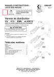
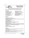
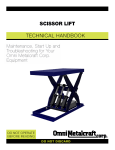
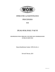
1
Instructions -- Parts List
WITH OR WITHOUT ELECTRONIC METERS
V5t V12t EM6t and
EM12tDispense Valves
308642P
EN
For dispense of petroleum and synthetic based oils.
1500 psi (10 MPa, 102 bar) Maximum Working Pressure
Important Safety Instructions
Read all warnings and instructions in this manual.
Save these instructions.
NotesSee the list on page 3 for Model Numbers
and configurations.
See manual 307965 for information on electronic
meters 244075 and 244076.
EM12
Model 238641
06294A
V12
Model 238644
06292A
Table of Contents
Models . . . . . . . . . . . . . . . . . . . . . . . . . . . . . . . . . . 3
Warnings . . . . . . . . . . . . . . . . . . . . . . . . . . . . . . . . 4
Installation . . . . . . . . . . . . . . . . . . . . . . . . . . . . . . . 6
Operation . . . . . . . . . . . . . . . . . . . . . . . . . . . . . . . 9
Troubleshooting . . . . . . . . . . . . . . . . . . . . . . . . . 10
Service . . . . . . . . . . . . . . . . . . . . . . . . . . . . . . . . 11
Parts — EM12 and V12 Dispense Valves . . . 12
Parts — EM6 Dispense Valves . . . . . . . . . . . . 13
Parts — V5 Dispense Valves . . . . . . . . . . . . . . 14
Technical Data . . . . . . . . . . . . . . . . . . . . . . . . . . 15
Graco Standard Warranty . . . . . . . . . . . . . . . . 16
Graco Phone Number . . . . . . . . . . . . . . . . . . . . 16
Bare Valve
Model 238646
8537A
EM6
Model 243599
TI0407
GRACO INC. P.O. BOX 1441 MINNEAPOLIS, MN 55440--1441
Copyright 2002, Graco Inc. is registered to I.S. EN ISO 9001
Notes
2
308642
Models
Non-Metered Valves
V12 -- with trigger lock
With Extension
Metered Valves
EM12 -- with trigger lock
English Meter
238636 3/4 in. swivel, rigid extension
238644 3/4 in. swivel, rigid extension
238637 3/4 in. swivel, flex extension
238645 3/4 in. swivel, flex extension
238640 1/2 in. swivel, rigid extension
238651 1/2 in. swivel, rigid extension
238652 1/2 in. swivel, flex extension
238641 1/2 in. swivel, flex extension
Metric Meter
238638 3/4 in. swivel, rigid extension
V5 -- with trigger lock
With Extension
238639 3/4 in. swivel, flex extension
238642 1/2 in. swivel, rigid extension
238643 1/2 in. swivel, flex extension
222411, Series C, 1/2 in. swivel, oil nozzle/extension
222412, Series C, 1/2 in. swivel, gear lube extension
222413, Series C, 1/2 in. swivel, ATF nozzle/extension
EM6 -- without trigger lock
English Meter
243599 1/2 in. swivel, rigid extension
Bare Valves
243600 1/2 in. swivel, gear lube
243601 1/2 in. swivel, flex extension
238646 3/4 in. swivel, no extension, with trigger lock
Metric Meter
238647 1/2 in. swivel, no extension, with trigger lock
243602 1/2 in. swivel, rigid extension
243992 1/2 in. swivel, no extension, without trigger
lock
243603 1/2 in. swivel, gear lube
243604 1/2 in. swivel, flex extension
308642
3
Warnings
Warning Symbol
Caution Symbol
WARNING
CAUTION
This symbol alerts you to the possibility of serious
injury or death if you do not follow the instructions.
This symbol alerts you to the possibility of damage to
or destruction of equipment if you do not follow the
instructions.
WARNING
WARNING
EQUIPMENT MISUSE HAZARD
Equipment misuse can cause the equipment to rupture or malfunction and result in serious injury.
INSTRUCTIONS
D This equipment is for professional use only.
D Read all instruction manuals, tags, and labels before you operate this equipment.
D Use the equipment only for its intended purpose. If you are not sure, call your Graco distributor.
D Do not alter or modify this equipment. Use only genuine Graco parts and accessories.
D Check equipment daily. Repair or replace worn or damaged parts immediately.
D Do not exceed the maximum working pressure of the lowest rated system component. Refer to
the Technical Data on page 15 for the maximum working pressure of this component.
D Use fluids and solvents which are compatible with the equipment wetted parts. Refer to the
Technical Data section of all equipment manuals. Read the fluid and solvent manufacturer’s
warnings.
D Do not use 1,1,1--trichloroethane, methylene chloride, other halogenated hydrocarbon solvents or
fluids that contain such solvents in pressurized aluminum equipment. Such use could result in a
chemical reaction, with the possibility of explosion.
D Do not use hoses to pull equipment.
D Route hoses away from traffic areas, sharp edges, moving parts, and hot surfaces. Do not
expose Graco hoses to temperatures above 180_ F (82_ C) or below --40_ F (--40_ C).
D Do not lift pressurized equipment.
D Comply with all applicable local, state, and national fire, electrical, and safety regulations.
4
308642
WARNING
WARNING
SKIN INJECTION HAZARD
Fluid from the dispensing valve, leaks, or ruptured components can inject fluid into your body and
cause extremely serious injury, including the need for amputation. Fluid splashed in the eyes or on
the skin can also cause serious injury.
D Fluid injected into the skin may look like just a cut, but it is a serious injury. Get immediate
surgical treatment.
D Do not point the dispensing valve at anyone or at any part of the body.
D Do not put your hand or fingers over the end of the dispensing valve.
D Do not stop or deflect leaks with your hand, body, glove or rag.
D Use only extensions and nozzles that are designed for use with your dispensing valve.
D Do not use a low-pressure flexible extension with this equipment.
D Follow the Pressure Relief Procedure on page 9 before you clean, check, or service the
equipment.
D Tighten all fluid connections before you operate the equipment.
D Check the hoses, tubes, and couplings daily. Replace worn or damaged parts immediately. Do
not repair high pressure couplings; you must replace the entire hose.
WARNING
WARNING
CALIFORNIA PROPOSITION 65
This product contains a chemical known to the State of California to cause cancer, birth defects or
other reproductive harm. Wash hands after handling.
308642
5
Installation
See manual 307965 for electronic meters installation, operation, parts, and cautions and warnings.
NOTE: Numbers in parenthesis, for example (7), and in the Parts Drawings are reference numbers
in the Parts List on page12.
Typical Installation
Fig. 1 shows a typical installation. Additionally, these
dispense valves can be installed on a console.
CAUTION
Do not use this electronic metered dispense
valve on non-Graco consoles. Such use could
result in the trigger becoming inadvertently
pressed while the dispense valve is stowed.
H
Thermal relief kit (required) Part No. 237904
Install downstream from pump.
J
Fluid shut-off valve
K
Hose
L
Hose reel fluid inlet hose
M
Hose reel
N
Metered dispense valve
The installation shown in Fig. 1 is only a guide. The
components shown are typical; however, it is not a
complete system design. Contact your Graco distributor for assistance in designing a system to suit your
particular needs.
J
L
H
KEY DESCRIPTION
CAUTION
M
To prevent line contamination, which can cause
equipment malfunction or damage, flush the lines
before you install the equipment in the system.
K
WARNING
N
04472A
Fig. 1
6
308642
FIRE AND EXPLOSION HAZARD
The movement of fluids through the
dispensing system generates static
electricity. The static electricity can
cause volatile fumes to ignite, resulting in explosion
and fire. The dispensing system must always be
grounded. See Grounding on page 8.
Installation
Pre-Installation Procedure
Existing Installation
1. Relieve the pressure.
1. Relieve the pressure.
WARNING
WARNING
To reduce the risk of serious injury whenever you
are instructed to relieve pressure, always follow the
Pressure Relief Procedure on page 9.
2. Close the fluid shut-off valve (item J in Fig. 1).
To reduce the risk of serious injury, whenever you
are instructed to relieve pressure, always follow the
Pressure Relief Procedure on page 9.
2. Loosen and disconnect the hose from the old
dispense valve (the one that you are replacing).
3. Ground the hose and reel or console. See
Grounding on page 8. Do not use PTFE tape
on the pipe joints; it may cause a loss of ground
across the pipe joint.
For steps 3 to 5, see Fig. 2.
Installation Procedure
NOTE: Do not over tighten the extension tube
assembly by using the nozzle adapter to hand turn the
nozzel. For rigid extensions, thread the extension
in at least three full turns, position the extension
for proper alignment, and tighten the sealing
nut (7). The PTFE seal on the sealing nut must
face the valve housing.
CAUTION
If this is a new installation, or if the oil in the
lines is contaminated, flush the lines before you
install the dispensing valve.
New Installation
1. Relieve the pressure.
WARNING
To reduce the risk of serious injury, whenever you
are instructed to relieve pressure, always follow the
Pressure Relief Procedure on page 9.
Steps 2 to 6 are the Flushing Procedure.
2. Close the fluid shut-off valve (J) at each dispense
position.
3. Make sure the main fluid outlet valve at the pump
is closed, the air pressure to the pump motor is
adjusted, and the air valve is open. Slowly open
main fluid valve.
3. Thread the extension (26a) into the outlet of the
dispense valve, and tighten firmly.
4. Apply thread sealant to the male threads of the
hose fitting, thread the hose fitting into the swivel
(20), and tighten firmly.
5. Thread the new nozzle (8) or nozzle adapter onto
the extension, and tighten firmly.
6. Open all dispense position shut-off valves, and
start the pump to pressurize the system. See the
Operation section for proper operation.
7. For metered dispense valves, to ensure dispensing accuracy, purge all air from the fluid lines and
dispense valves before you use them.
Model shown is a V12 with
a 75_ bend rigid extension.
7
4. Place the hose end (with no dispense valve connected) into a container for waste oil. Secure the
hose in the container so it will not come out during
flushing. If you have multiple dispense positions,
first flush the dispense position farthest from the
pump, and work your way toward the pump.
26a
8
5. Slowly open the shut-off valve (J) at the dispense
position. Flush out a sufficient amount of oil to
ensure that the entire system is clean, and close
the valve.
6. Repeat step 5 at all other dispense positions.
20
06292A
Fig. 2
308642
7
Installation
Grounding
Proper grounding is an essential part of maintaining a
safe system.
To reduce the risk of static sparking, ground all system
components per local and national electrical codes.
Refer to the user manuals for the pump and other
system components to ground the following:
8
308642
D Pump: Follow manufacturer’s recommendations.
D Air and Fluid hoses: Use only grounded hoses.
D Air compressor: Follow manufacturer’s recommendations.
D Fluid supply container: Follow your local code.
D To maintain grounding continuity when flushing or
relieving pressure, always hold a metal part of the
valve firmly to the side of a grounded metal pail,
then trigger the valve.
Operation
Pressure Relief Procedure
WARNING
PRESSURIZED EQUIPMENT HAZARD
The equipment stays pressurized until
pressure is manually relieved. To
reduce the risk of serious injury from
pressurized fluid, accidental spray from the
dispenser or splashing fluid, follow the Pressure
Relief Procedure whenever you
D Are instructed to relieve pressure
D Check, clean, or service any system equipment
D Install or clean fluid nozzles
1. Turn off the power supply to the pump.
2. Trigger the valve into a waste container to relieve
pressure.
3. Open any bleed-type master air valves and fluid
drain valves in the system.
4. Leave the drain valve open until you are ready to
pressurize the system.
If you suspect that the dispensing valve, extension, or
nozzle is clogged or that pressure has not been fully
relieved after following the steps above, very slowly
loosen a fitting on the fluid line to relieve pressure
gradually, then loosen it completely, then clear the
clog.
WARNING
To reduce the risk of a serious bodily injury, including fluid injection, never exceed the maximum
working pressure of the valve you are using or of
the lowest rated component in your system.
Dispensing Procedure
See instruction manual 307965 for electronic meter
operation.
NOTE: Before you begin, make sure you understand
how to unlock the trigger. Model EM6 does not have
a trigger lock.
1. Pull the trigger toward the valve body to open the
valve and begin dispensing.
2. Lock the valve open by keeping the trigger
squeezed and depressing the trigger lock button
(25 in the Parts Drawing). Then release the
trigger, releasing your forefinger from the trigger
lock last.
3. Pull the trigger toward the valve body to release
the trigger lock. The trigger lock disengages.
4. Release the trigger to stop dispensing.
308642
9
Troubleshooting
Relieve the pressure before you check or repair the
dispensing valve. Be sure all other valves and controls
and the pump are operating properly.
Problem
WARNING
To reduce the risk of serious injury whenever you
are instructed to relieve pressure, always follow the
Pressure Relief Procedure on page 9.
Cause
Solution
Display does not activate or is
showing unintelligent
characters.
Electronic control is malfunctioning.
Replace the electronic control.
See instruction manual 307965.
Slow or no fluid flow
Filter is clogged, or
1. Relieve the pressure.
Pump pressure is low, or
2. Clean or replace the filter (10).
See Filter Replacement on
page 11.
Shutoff valve is not fully open, or
Foreign material is jammed in the
metering element.
Oil leaks from swivel.
Swivel is loose.
3. If the problem remains, contact
your Graco distributor for repair
or replacement.
Torque the swivel (20) to 15 to 20
ft-lb (20 to 27 N-m).
If the problem remains, contact your
Graco distributor for repair or
replacement.
O-ring is worn or damaged.
Replace the o-ring (6), and torque the
swivel (20) to 15 to 20 ft-lb (20 to 27
N-m).
If the problem remains, contact your
Graco distributor for repair or
replacement.
Oil drips from nozzle. *
Nozzle is damaged or obstructed.
Inspect the nozzle for damage or
obstructions, and replace if damaged.
Valve leaks.
O-rings or valve seat are worn or
damaged.
Replace the o-rings (15) and/or the
valve seat (29).
See Valve Handle Repair on
page 11.
* Some fluid weepage is possible in applications where thermal expansion of fluid is possible.
10
308642
Service
NOTE: See instruction manual 307965 for electronic meter service instructions.
Valve Handle Repair
6. Lubricate the cam, and slide it into the valve
handle, making sure the notch is oriented as
shown in Fig. 3. Ensure that the large end of the
pushrod is resting in the notch of the cam.
See Fig. 3.
NOTE: The large end of the pushrod (30) fits into a
notch in the cam (21), which is part of the trigger
assembly. It is important that you know this before you
remove or install parts.
7. Replace the screws (14) and washers (28), and
torque the screws to 15 to 25 in-lb (1.7 to
2.8 N-m).
1. Relieve the pressure.
8. Replace the swivel (20), and torque to 15 to 20
ft-lb (20 to 27 N-m).
WARNING
Filter Replacement
To reduce the risk of serious injury, when you are
instructed to relieve pressure, always follow the
Pressure Relief Procedure on page 9.
See Fig. 3.
1. Relieve the pressure.
WARNING
2. If you are replacing the o-rings (15), or the cam
(21), or the push rod (30), remove the swivel (20),
and remove the internal pieces. You must
remove the cam in order to get the push rod
out of the outlet end of the valve handle.
To reduce the risk of serious injury, when you are
instructed to relieve pressure, always follow the
Pressure Relief Procedure on page 9.
3. Remove the screws (14) and washers (28), and
remove the trigger (24). Push the cam (21) out of
the valve handle (18). Replace the o-rings (15)
and/or the cam.
2. Unscrew the hose fitting from the swivel (20).
3. Remove and replace the filter (10), which is inside
the valve handle (18). Make sure the filter is
oriented as shown in Fig. 3.
4. Replace any worn or broken parts.
4. Thread the hose fitting into the swivel (20), and
tighten. Make sure the swivel (20) is torqued to
15 to 20 ft-lb (20 to 27 N-m).
5. Reassemble the internal pieces. The push rod
(30) must be inserted through the outlet end of
the valve handle before the cam (21) is
installed.
14
30
28
NOTE: For torque specifications and lubrication
instructions, see the service notes in the Parts
Drawings on pages 12, 13 and 14. EM6 models do not
have trigger lock parts 11, 25, and 27.
15
27
11
18
15
28
notch
25
14
21
10
20
24
Fig. 3
308642
7854B
11
Parts — EM12 and V12 Dispense Valves
EM12 Models: 238636 to 238643 -- with trigger lock
(with electronic meter and extension)
V12 Models:
238644, 238645, 238651,
and 238652 -- with trigger lock
(no meter, includes extension)
Bare Valves:
238646 and 238647 -- with trigger lock
(no meter, no extension)
7
26a
36
8
Includes items 6, 10--25, and 27--30
5
2
14
35
26b
30
28
15
18
16
27
11
10
6
20
Ref
No.
6
7
Part No.
111137
112841
8
238400
10
11
12
14
15
16
18
20
185416
113924
113493
110637
113574
113627
191074
238398
238399
12
308642
1
3
21
29
12
4
4
8
28
14
25
4
24
Description
O--RING, valve/swivel
For Models 238636 to 238645,
238651, and 238652
For Models 238646 and 238647
NUT, seal; 1/2--14 npt
For Models 238636, 238638,
238640, 238642, 238644, and
238651
NOZZLE, oil
For Models 238636 to 238645,
238651, and 238652
FILTER
SPRING, compression
SPRING, compression
SCREW, machine
SEAL, o-ring
WASHER, plain
HANDLE, valve
SWIVEL; 3/4--14 npt
For Models 238636 to 238639
and 238644 to 238646
SWIVEL; 1/2--14 npt
For Models 238640 to 238643,
238647, 238651 and 238652
15
2
1
Torque to 15 to 20 ft-lb (20 to 27 N-m).
2
Torque to 15 to 25 in-lb (1.7 to 2.8 N-m).
3
Apply lubricant to threads when reassembling.
4
Apply lubricant to packings and sealing
surfaces when reassembling.
5
Apply thread sealant when reassembling.
Qty
Ref
No.
Part No.
Description
2
1
21
24
25
26a
191315
191320
191321
191403
1
26b
238401
1
1
1
1
2
2
1
1
27
28
29
30
35
192106
191552
191313
192501
158491
36
244075
CAM
TRIGGER
TRIGGER LOCK
TUBE, 75_ bend; 1/2 npt
For Models 238636, 238638,
238640, 238642, 238644, and
238651
HOSE, flexible; 1/2 npt
For Models 238637, 238639,
238641, 238643, 238645,
and 238652
GUIDE, spring
WASHER, flat
SEAT, valve
ROD, push
NIPPLE
For Models 238636 to 238643
METER, electronic; English
For Models 238636, 238637,
238640, and 238641
METER, electronic; metric
For Models 238638, 238639,
238642, and 238643
1
1
1
244076
06293C
Qty
1
1
1
1
1
1
2
1
1
1
1
1
1
Parts — EM6 Dispense Valves
EM6 Models:
243599 to 243604 -- without trigger lock
(with electronic meter and extension)
Bare Valve:
243992 bare valve -- without trigger lock
(no meter, no extension)
28c
28b
Includes items 6, 10--23, and 25--27
7
28a
29c
33
5
2
13
29b
32
29a
27
25
17
14
4
20
14
30a
4
11
10
18
13
15
6
1
30b
25
26
4
23
3
Ref
No.
Part No.
Description
6
111137
O--RING, valve/swivel
For Models 243599 to 243604,
For Model 243992
NUT, seal; 1/2--14 npt
For Models 243599 to 243604,
FILTER
SPRING, compression
SCREW, machine
SEAL, quad ring
WASHER, plain
HANDLE, valve
SWIVEL; 1/2--14 npt
CAM
TRIGGER
NOZZLE, rigid extension
For Models 243599, and 243602
Includes items 28a--28c
. BUSHING; 1/2 npt(m) x 3/8 npt(f)
. TUBE, nozzle
. NOZZLE, non--drip
7
112841
10
11
13
14
15
17
18
20
23
28
185416
113493
110637
113574
113627
191074
238399
191315
191320
203265
28a
28b
28c
100081
159246
203655
Qty
2
1
1
1
1
2
2
1
1
1
1
1
1
1
1
1
TI0408
2
1
Torque to 15 to 20 ft-lb (20 to 27 N-m).
2
Torque to 15 to 25 in-lb (1.7 to 2.8 N-m).
3
Apply lubricant to threads when reassembling.
4
Apply lubricant to packings and sealing
surfaces when reassembling.
5
Apply thread sealant when reassembling.
Ref
No.
29
Part No.
201701
29a
29b
29c
30
100206
187046
201540
203687
30a
109160
30b
25
26
27
32
203655
191552
191313
192501
158491
33
244075
244076
Description
NOZZLE, gear lube
For Models 243600 and 243603
Includes items 29a--29c
. BUSHING; 1/2 npt(m) x 1/4 npt(f)
. TUBE, nozzle
. NOZZLE, non--drip
NOZZLE, flexible extension
For Models 243601 and 243604
Includes items 30a--30b
. HOSE, coupled; 1 ft (0.3 m);
1/2--14 npt(m) x 1/4--18 npt(f)
. NOZZLE, non--drip
WASHER, flat
SEAT, valve
ROD, push
NIPPLE
For Models 243599 to 243604
METER, electronic; English
For Models 243599, 243600,
and 243601
METER, electronic; metric
For Models 243602, 243603,
and 243604
308642
Qty
1
1
1
1
1
1
1
1
1
1
1
1
13
Parts — V5 Dispense Valves
Model 238647 ---- Bare Valve
2
Ref
No.
1*
Part No.
238647
Description
VALVE
Qty
1
Model 222411, Series C ---- For Oil
3
Ref
No.
1*
2
1
Part No.
238647
203265
Description
VALVE
NOZZLE, oil
See parts list on page 13.
Qty
1
1
Model 222412, Series C ---- For Gear Lube
4
Ref
No.
1*
3
Part No.
238647
201701
Description
VALVE
NOZZLE, gear lube
See parts list on page 13.
Qty
1
1
Model 222413, Series C ---- For A.T.F.
7853A
Ref
No.
1*
4
Part No.
238647
203687
Description
VALVE
NOZZLE, A.T.F.
See parts list on page 13.
Qty
1
1
* See parts below.
Model 238647 ---- Bare Valve, with trigger lock
Ref
No.
Part No.
Description
6
10
11
12
14
15
16
18
20
21
24
25
27
28
29
30
111137
185416
113924
113493
110637
113574
113627
191074
238399
191315
191320
191321
192106
191552
191313
192501
O-RING, valve/swivel
FILTER
SPRING, compression
SPRING, compression
SCREW, machine
SEAL, o-ring
WASHER, plain
HANDLE, valve
SWIVEL; 1/2--14 npt
CAM
TRIGGER
TRIGGER LOCK
GUIDE, spring
WASHER, flat
SEAT, valve
ROD, push
Qty
1
1
1
1
2
2
1
1
1
1
1
1
1
2
1
1
1
Torque to 15 to 20 ft-lb (20 to 27 N-m).
2
Torque to 15 to 25 in-lb (1.7 to 2.8 N-m).
3
Apply lubricant to threads when reassembling.
4
Apply lubricant to packings and sealing
surfaces when reassembling.
14
28
15
4
28
27
11
25
16
18
10
14
2
3
24
6
14
4
21
12
1
30
15
29
20
2
308642
4
7854B
Technical Data
NOTE: See instruction manual 307965 for electronic meter Technical Data.
Recommended maximum flow rate*
V5 dispense valves . . . . . . . . . . . . . . . . . . . . . . . . . . . . . . . . . . . . . . . . . . . . . . . . . . . . . . . . . . . . . . . . . . . 5.0 gpm (18.9 lpm)
EM6 dispense valves . . . . . . . . . . . . . . . . . . . . . . . . . . . . . . . . . . . . . . . . . . . . . . . . . . . . . . . . . . . . . . . . . 6.0 gpm (23.0 lpm)
V12 and EM12 dispense valves . . . . . . . . . . . . . . . . . . . . . . . . . . . . . . . . . . . . . . . . . . . . . . . . . . . . . . 12.0 gpm (45.4 lpm)
Maximum operating pressure . . . . . . . . . . . . . . . . . . . . . . . . . . . . . . . . . . . . . . . . . . . . . . . . . . . . . . . . . . . . . . . . . . . 1500 psi
(10 MPa, 102 bar)
Weight (without meter) . . . . . . . . . . . . . . . . . . . . . . . . . . . . . . . . . . . . . . . . . . . . . . . . . . . . . . . . . . . . . . . . . . . 0.4 lb (0.18 kg)
Operating temperature range . . . . . . . . . . . . . . . . . . . . . . . . . . . . . . . . . . . . . . . . . . . . . . . . --4_ to 130_ F (--20_ to 55_ C)
Storage temperature range . . . . . . . . . . . . . . . . . . . . . . . . . . . . . . . . . . . . . . . . . . . . . . . . . --40_ to 140_ F (--40_ to 60_ C)
Inlet sizes . . . . . . . . . . . . . . . . . . . . . . . . . . . . . . . . . . . . . . . . . . . . . . . . . . . . . . . . . . . . . . . . . . . . . . . . . . . 1/2 npt and 3/4 npt
See page 3 for model numbers and configurations.
Outlet size . . . . . . . . . . . . . . . . . . . . . . . . . . . . . . . . . . . . . . . . . . . . . . . . . . . . . . . . . . . . . . . . . . . . . . . . . . . . . . . . . . . . . 1/2 npt
Wetted parts . . . . . . . . . . . . . . . . . . . . . . . . . . . . . . . . . . . . . . . . . . . . . . . . . . . . . . . . . . . . . . . . . . aluminum, stainless steel,
carbon steel, acetal, nitrile rubber, Geolastt
* Under normal operating conditions
Geolastt is a trademark of Advanced Elastomer Systems.
308642
15
Graco Standard Warranty
Graco warrants all equipment manufactured by Graco and bearing its name to be free from defects in material and workmanship on the
date of sale to the original purchaser for use. With the exception of any special, extended, or limited warranty published by Graco,
Graco will, for a period of twelve months from the date of sale, repair or replace any part of the equipment determined by Graco to be
defective. This warranty applies only when the equipment is installed, operated and maintained in accordance with Graco’s written
recommendations.
This warranty does not cover, and Graco shall not be liable for general wear and tear, or any malfunction, damage or wear caused by
faulty installation, misapplication, abrasion, corrosion, inadequate or improper maintenance, negligence, accident, tampering, or substitution of non-Graco component parts. Nor shall Graco be liable for malfunction, damage or wear caused by the incompatibility of
Graco equipment with structures, accessories, equipment or materials not supplied by Graco, or the improper design, manufacture,
installation, operation or maintenance of structures, accessories, equipment or materials not supplied by Graco.
This warranty is conditioned upon the prepaid return of the equipment claimed to be defective to an authorized Graco distributor for
verification of the claimed defect. If the claimed defect is verified, Graco will repair or replace free of charge any defective parts. The
equipment will be returned to the original purchaser transportation prepaid. If inspection of the equipment does not disclose any defect
in material or workmanship, repairs will be made at a reasonable charge, which charges may include the costs of parts, labor, and
transportation.
THIS WARRANTY IS EXCLUSIVE, AND IS IN LIEU OF ANY OTHER WARRANTIES, EXPRESS OR IMPLIED, INCLUDING BUT
NOT LIMITED TO WARRANTY OF MERCHANTABILITY OR WARRANTY OF FITNESS FOR A PARTICULAR PURPOSE.
Graco’s sole obligation and buyer’s sole remedy for any breach of warranty shall be as set forth above. The buyer agrees that no other
remedy (including, but not limited to, incidental or consequential damages for lost profits, lost sales, injury to person or property, or any
other incidental or consequential loss) shall be available. Any action for breach of warranty must be brought within two (2) years of the
date of sale.
Graco makes no warranty, and disclaims all implied warranties of merchantability and fitness for a particular purpose in connection
with accessories, equipment, materials or components sold but not manufactured by Graco. These items sold, but not manufactured
by Graco (such as electric motors, switches, hose, etc.), are subject to the warranty, if any, of their manufacturer. Graco will provide
purchaser with reasonable assistance in making any claim for breach of these warranties.
In no event will Graco be liable for indirect, incidental, special or consequential damages resulting from Graco supplying equipment
hereunder, or the furnishing, performance, or use of any products or other goods sold hereto, whether due to a breach of contract,
breach of warranty, the negligence of Graco, or otherwise.
FOR GRACO CANADA CUSTOMERS
The parties acknowledge that they have required that the present document, as well as all documents, notices and legal proceedings
entered into, given or instituted pursuant hereto or relating directly or indirectly hereto, be drawn up in English. Les parties reconnaissent avoir convenu que la rédaction du présente document sera en Anglais, ainsi que tous documents, avis et procédures judiciaires
exécutés, donnés ou intentés à la suite de ou en rapport, directement ou indirectement, avec les procedures concernées.
Graco Phone Numbers
TO PLACE AN ORDER, contact your Graco distributor, or call one of the following numbers
to identify the distributor closest to you:
1--800--533--9655 Toll Free
612--623--6928
612--378--3590 Fax
All written and visual data contained in this document reflect the latest product information available at the time of publication.
Graco reserves the right to make changes at any time without notice.
This manual contains English. MM 308642
For patent information: www.graco.com/patents
Graco Headquarters: Minneapolis
International Offices: Belgium, Korea, China, Japan
GRACO INC.
P.O. BOX 1441
MINNEAPOLIS, MN 55440--1441
www.graco.com
02/1997, Revised December 2014
16
308642