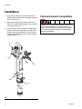
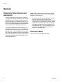
1
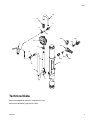
Instructions - Parts List
Electronic
POWERFIL Metered
Dispense Pumps
307637R
Used for low-volume dispense of petroleum-base lubricants. For professional use only.
Model 239702
Pump with gallon/quart/liter Electronic Meter
100 psi (0.7 MPa, 7 bar) Maximum Working Pressure
Model 222602
Unmetered pump
100 psi (0.7 MPa, 7 bar) Maximum Working Pressure
Important Safety Instructions
Read all warnings and instructions in this
manual. Save these instructions.
EN
Warnings
Warnings
The following warnings are for the setup, use, grounding, maintenance, and repair of this equipment. The exclamation point symbol alerts you to a general warning and the hazard symbols refer to procedure-specific risks. When
these symbols appear in the body of this manual or on warning labels, refer back to these Warnings. Product-specific
hazard symbols and warnings not covered in this section may appear throughout the body of this manual where
applicable.
WARNING
FIRE AND EXPLOSION HAZARD
When flammable fluids are present in the work area, such as gasoline and windshield wiper fluid, be
aware that flammable fumes can ignite or explode. To help prevent fire and explosion:
• Use equipment only in well ventilated area.
• Eliminate all ignition sources, such as cigarettes and portable electric lamps.
• Keep work area free of debris, including rags and spilled or open containers of solvent and gasoline.
• Do not plug or unplug power cords or turn lights on or off when flammable fumes are present.
• Ground all equipment in the work area.
• Use only grounded hoses.
• Stop operation immediately if static sparking occurs or you feel a shock. Do not use equipment
until you identify and correct the problem.
• Keep a working fire extinguisher in the work area.
PRESSURIZED EQUIPMENT HAZARD
Fluid from the equipment, leaks, or ruptured components can splash in the eyes or on skin and cause
serious injury.
• Follow the Pressure Relief Procedure when you stop spraying/dispensing and before cleaning,
checking, or servicing equipment.
• Tighten all fluid connections before operating the equipment.
• Check hoses, tubes, and couplings daily. Replace worn or damaged parts immediately.
EQUIPMENT MISUSE HAZARD
Misuse can cause death or serious injury.
• Do not operate the unit when fatigued or under the influence of drugs or alcohol.
• Do not exceed the maximum working pressure or temperature rating of the lowest rated system component. See Technical Data in all equipment manuals.
• Use fluids and solvents that are compatible with equipment wetted parts. See Technical Data in all
equipment manuals. Read fluid and solvent manufacturer’s warnings. For complete information
about your material, request MSDS from distributor or retailer.
• Turn off all equipment and follow the Pressure Relief Procedure when equipment is not in use.
• Check equipment daily. Repair or replace worn or damaged parts immediately with genuine manufacturer’s replacement parts only.
• Do not alter or modify equipment. Alterations or modifications may void agency approvals and create
safety hazards.
• Make sure all equipment is rated and approved for the environment in which you are using it.
• Use equipment only for its intended purpose. Call your distributor for information.
• Route hoses and cables away from traffic areas, sharp edges, moving parts, and hot surfaces.
• Do not kink or over bend hoses or use hoses to pull equipment.
• Keep children and animals away from work area.
• Comply with all applicable safety regulations.
2
307637R
Warnings
WARNING
PRESSURIZED ALUMINUM PARTS HAZARD
Use of fluids that are incompatible with aluminum in pressurized equipment can cause serious chemical
reaction and equipment rupture. Failure to follow this warning can result in death, serious injury, or property damage.
• Do not use 1,1,1-trichloroethane, methylene chloride, other halogenated hydrocarbon solvents or fluids containing such solvents.
• Many other fluids may contain chemicals that can react with aluminum. Contact your material supplier for compatibility.
PERSONAL PROTECTIVE EQUIPMENT
Wear appropriate protective equipment when in the work area to help prevent serious injury, including
eye injury, hearing loss, inhalation of toxic fumes, and burns. This protective equipment includes but is
not limited to:
• Protective eyewear, and hearing protection.
• Respirators, protective clothing, and gloves as recommended by the fluid and solvent manufacturer
307637R
3
Installation
Installation
1. Apply thread sealant to the male threads of the
bushing (20g) and install the air regulator (20) at the
pump air inlet. (FIG. 1)
2. Apply thread sealant to the male threads of the
elbow (11) and install the dispense valve assembly
at the pump outlet. (FIG. 1)
3. Install the pump in the bung hole of a fluid supply
container. Screw the bung adapter (A) tightly into
the hole. Raise the pump about 1/2 inch (12 mm)
from the bottom of the container. Tighten the bung
adapter screw. (FIG. 1)
Fluid and Solvent Compatibility
To reduce the risk of component rupture, which can
result in serious bodily injury, all fluids used in this
pump must be chemically compatible with the wetted
parts shown on page 8. Consult your fluid suppplier
to ensure compatibility.
12
1a
20g
20
11
A
FIG. 1
4
307637R
Operation
Operation
position to open the valve. Slowly open the regulator
until the desired fluid flow is obtained. Air pressure
of 30-40 psi (0.21-0.28 MPa, 2.1-2.8 bar) is recommended to provide sufficient fluid flow without
splashing.
1. Start the pump. See instruction manual 307906,
supplied.
To use the electronic meter, see instruction manual
308687, supplied, for detailed operating instructions.
2. To dispense fluid and adjust fluid flow from the
valve, start with the air supply turned off at the regulator (20). Hold the valve handle (1a) in the down
Maintenance
Electronically Metered Models
Only
For electroniccaly metered models, see instruction manual 308687, supplied.
Troubleshooting
Check all possible problems and causes before disassembling gun.
Problem
Valve will not dispense fluid
Fluid flow from dispense valve is low
or irregular
Leakage at valve seat
Fluid meter registers incorrectly or
not at all
307637R
Cause
Solution
Pump is not operating
Check pump. See manual 307906
Valve diffuser is clogged
Remove and clean valve diffuser
Strainer, if used, is clogegd
Remove and clean strainer
Electronic meter is malfunctioning
Replace dispense meter. See manual 308687
Pump is malfunctioning
Check pump. See manual 307906
Valve diffuser is clogged
Remove and clean valve diffuser
Strainer, if used, is clogged
Remove and clean strainer
Valve seal is worn or damaged
Replace
Valve spring is weak or broken
Replace
Electronic control is malfunctioning
Replace. See manual 308687
5
Service
Service
Dispensing Valve Service and
Adjustment
NOTE: Clearance between the valve handle (1b) and
the valve housing (1k) is necessary to ensure proper
dispensing valve operation.
•
To clean or replace the valve seal (1f), screw the
valve nozzle (1e) off the valve housing (1k). Remove
the gasket (1h). Unscrew ther etaining screw (1g)
from the valve stem (1j). Remove the valve seal (1f).
See the Parts Drawing, page 7. Clean and inspect
all parts and replace as necessary. Reassemble the
valve, making sure the gasket (1h) is in place.
•
•
To adjust the dispensing valve, drive the pin (1m)
out of the handle (1b) witha 1/8 in. drift pin. Remove
the valve handle (1b) from the stem (1j). See Parts
Drawing, page 7. Turn the adjusting nut (1c) upward
until a small gap (0.040 in maximum) exists between
the handle (1b) and the valve housing (1k) when the
valve is reassembled. Reinstall the handle on the
stem. Reinstall the pin.
6
To replace the valve stem (1j), spring (1l) or packings (1d), remove the valve handle (1b) as
described above. Screw the valve nozzle (1e) off the
valve housing (1k). Remove the gasket (1h). Screw
adjusting nut (1c) off the valve stem. Pull the stem
out through the bottom of the valve housing. See
Parts Drawing, page 7. Clean and inspect all parts
and replace as necessary. Reassemble valve.
Adjust it as described above.
Electronic Meter
See instruction manual 308687 (included).
307637R
Notes
Notes
307637R
7
Parts
Parts
Ref 1, Model 220110
Dispensing Valve
Ref.
1a
1b
1c
1d*
1e
1f*
1g
1h*
1j
1k
1l
1m
1n
1p
*
Part
108789
154773
154891
154594
166779
156312
156311
154779
154781
179932
150534
155473
112122
190223
Unmetered Dispesne Pump
Model 222602, without meter
Description
KNOB, handle
HANDLE
NUT, adjusting
PACKING, o-ring, nitrile rubber
NOZZLE, valve
SEAL, valve, nitrile rubber
SCREW, valve
GASKET
STEM, valve
HOUSING, valve
SPRING, compression
PIN, 5/32 in. x 1 in. long
ADAPTER, 3/8 in. (m x f) npt
RESTRICTOR
Qty.
1
1
1
2
1
1
1
1
1
1
1
1
1
1
Recommended “tool box” spare parts. Keep on hand
to reduce downtime.
1b
1a
1m
1c
Ref.
101
102
103
Part
Description
Qty.
222103 PUMP, see 307906 for parts
1
218115 UNMETERED DISPENSE KIT, see
1
parts below
109125 HOSE, air, 1/4” ID, 1/4” npt(mbe),
1
72” long
Electronic Metered Dispense Pump,
Model 239702, with gallon/quart/pin/liter
electronic meter
Ref.
101
102
Part
Description
222103 PUMP, see 307906 for parts
239703 ELECTRONIC METERED DISPENSE KIT, See parts below
Unmetered Dispense Kit, Model 218115,
Series E, Includes items 1, 11, 20, 22
Metered Dispense Kit, Model 239703, Series
E, Includes items 1-20
5
1p
4
1n
1k
3
Ref.
1
9
11
Part
220100
155699
157619
12
239824
13
14
158212
158256
16
18
20
186034
185163
218316
*1d
1
1l
1j
*1f
1g
20a 100403
20b 104655
20c 104815
*1h
2
1
2
3
4
5
8
Qty.
1
1
1e
Apply lubricant to o-ring.
20d 103656
20e 169969
20f 114558
Torque to 120 to 130 in-lb (14 to 15 N.m).
Apply lubricant to housing threads.
Press fit.
20g 100030
22
179928
Description
Qty.
VALVE, dispense
1
ELBOW, street, 3/8 npt (m x f)
1
ELBOW, street, 3/8 npt (f) x 3/4 npt
1
(m)
ELECTRONIC METER, See man1
ual 308687
BUSHING, 3/8 npt (f) x 1/2 npt (m)
1
UNION, adapter, 1/2 npt (m) x 3/8
1
npsm (f) swivel
TUBE
1
TUBE
1
AIR REGULATOR KIT, includes
1
items 20a-20g
PLUG, pipe, 1/8 npt
1
GAUGE, air pressure, 0-60 psi
1
(0-0.42 MPa, 0-4.2 bar)
REGULATOR, air pressure, 0-60 psi
1
(0-0.42 MPa, 0-4.2 bar)
NIPPLE, pipe, 1/8 npt
1
FITTING, air coupler, 1/8 npt (m)
1
COUPLER, air quick disconnect,
1
1/4 npt (f) inlet
BUSHING, pipe, 1/4 npt (m) x 1/8
1
npt (f)
TUBE
1
Turn nut (1c) upward until a small gap (0.040 in. max)
exists between the handle (1b) and the housing (1k).
Step 2 under maintenance.
307637R
Parts
18
14
9
1n
1p
20f
20b
12
1
20e
20c
13
1p
20d
20g
16
20a
101
1n
22
11
Technical Data
See manual 308687 for electronic meter technical data.
See manual 307906 for pump technical data.
307637R
9
Graco Standard Warranty
Graco warrants all equipment referenced in this document which is manufactured by Graco and bearing its name to be free from defects in
material and workmanship on the date of sale to the original purchaser for use. With the exception of any special, extended, or limited warranty
published by Graco, Graco will, for a period of twelve months from the date of sale, repair or replace any part of the equipment determined by
Graco to be defective. This warranty applies only when the equipment is installed, operated and maintained in accordance with Graco’s written
recommendations.
This warranty does not cover, and Graco shall not be liable for general wear and tear, or any malfunction, damage or wear caused by faulty
installation, misapplication, abrasion, corrosion, inadequate or improper maintenance, negligence, accident, tampering, or substitution of
non-Graco component parts. Nor shall Graco be liable for malfunction, damage or wear caused by the incompatibility of Graco equipment with
structures, accessories, equipment or materials not supplied by Graco, or the improper design, manufacture, installation, operation or
maintenance of structures, accessories, equipment or materials not supplied by Graco.
This warranty is conditioned upon the prepaid return of the equipment claimed to be defective to an authorized Graco distributor for verification of
the claimed defect. If the claimed defect is verified, Graco will repair or replace free of charge any defective parts. The equipment will be returned
to the original purchaser transportation prepaid. If inspection of the equipment does not disclose any defect in material or workmanship, repairs will
be made at a reasonable charge, which charges may include the costs of parts, labor, and transportation.
THIS WARRANTY IS EXCLUSIVE, AND IS IN LIEU OF ANY OTHER WARRANTIES, EXPRESS OR IMPLIED, INCLUDING BUT NOT LIMITED
TO WARRANTY OF MERCHANTABILITY OR WARRANTY OF FITNESS FOR A PARTICULAR PURPOSE.
Graco’s sole obligation and buyer’s sole remedy for any breach of warranty shall be as set forth above. The buyer agrees that no other remedy
(including, but not limited to, incidental or consequential damages for lost profits, lost sales, injury to person or property, or any other incidental or
consequential loss) shall be available. Any action for breach of warranty must be brought within two (2) years of the date of sale.
GRACO MAKES NO WARRANTY, AND DISCLAIMS ALL IMPLIED WARRANTIES OF MERCHANTABILITY AND FITNESS FOR A
PARTICULAR PURPOSE, IN CONNECTION WITH ACCESSORIES, EQUIPMENT, MATERIALS OR COMPONENTS SOLD BUT NOT
MANUFACTURED BY GRACO. These items sold, but not manufactured by Graco (such as electric motors, switches, hose, etc.), are subject to
the warranty, if any, of their manufacturer. Graco will provide purchaser with reasonable assistance in making any claim for breach of these
warranties.
In no event will Graco be liable for indirect, incidental, special or consequential damages resulting from Graco supplying equipment hereunder, or
the furnishing, performance, or use of any products or other goods sold hereto, whether due to a breach of contract, breach of warranty, the
negligence of Graco, or otherwise.
FOR GRACO CANADA CUSTOMERS
The Parties acknowledge that they have required that the present document, as well as all documents, notices and legal proceedings entered into,
given or instituted pursuant hereto or relating directly or indirectly hereto, be drawn up in English. Les parties reconnaissent avoir convenu que la
rédaction du présente document sera en Anglais, ainsi que tous documents, avis et procédures judiciaires exécutés, donnés ou intentés, à la suite
de ou en rapport, directement ou indirectement, avec les procédures concernées.
Graco Information
For the latest information about Graco products, visit www.graco.com.
TO PLACE AN ORDER, contact your Graco distributor or call to identify the nearest distributor.
Phone: 612-623-6928 or Toll Free: 1-800-533-9655, Fax: 612-378-3590
All written and visual data contained in this document reflects the latest product information available at the time of publication.
Graco reserves the right to make changes at any time without notice.
For patent information, see www.graco.com/patents.
Original instructions. This manual contains English. MM 307637
Graco Headquarters: Minneapolis
International Offices: Belgium, China, Japan, Korea
GRACO INC. AND SUBSIDIARIES • P.O. BOX 1441 • MINNEAPOLIS MN 55440-1441 • USA
Copyright 1983, Graco Inc. All Graco manufacturing locations are registered to ISO 9001.
www.graco.com
Revised January 2013