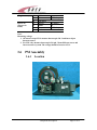
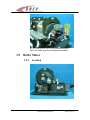
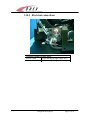
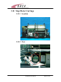
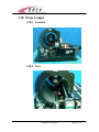
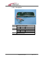
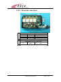
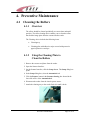
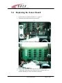
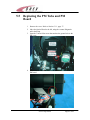
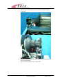
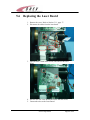
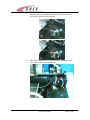
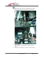
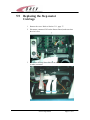
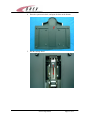
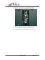
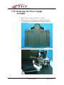
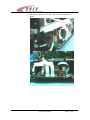
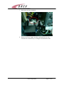
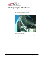
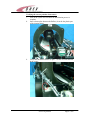
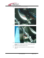
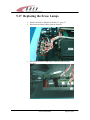
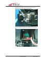
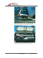
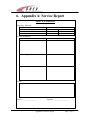
1
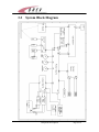
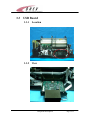
PcCR 1417 ACL4 System
(AA095042-00)
Automatic Cassette Loading Version
Service Manual
Catalog number: AT095005-02
September, 2003
Ver. 01
OREX Ltd. is a market innovator in the field of portable Computed Radiography
Technologies—designed and priced for low-volume clinic or field unit needs .
Founded in 1995 under the name of Digident, the company initially entered the market of
desktop dental radiography providing high quality, portable CR reading units for dental and
orthodontic professionals around the world. The secret of Digident/OREX’s rapid success lies
in the best cost-performance ratio on the market.
OREX designs, manufactures and markets phosphor image laser scanners. These units replace
the traditional x-ray film and light box. The scanners allow the user to immediately read the
x-ray image from the phosphor plate, and transfer it to a DICOM 3 compatible digital
computer file. Once transferred, users can manipulate the digital image for close-up
screening, or transmit it for long-distance consultation. After each scan, the phosphor plates
are automatically erased by the unit, ready for re-use.
OREX provides clients with a full solution including phosphor image plates, laser readers,
software for image processing, storage, retrieval and communication in Picture Archiving and
Communications System (PACS) compatible format.
The company’s mission is to become a leading provider of compact personal CR systems.
Following the successful penetration of the global dental market, the company changed its
name from Digident to OREX and expanded its markets and product lines to serve the dental,
medical, military, industrial and veterinary fields.
“We are committed to assisting our customers in obtaining maximum value
from OREX products by providing excellent support at exce ptional value.”
Technical Support
Israel Headquarters :
Tel: ++972-4-959-1331
Fax: ++972-4-959-1262
E-mail: [email protected]
US Office:
Tel: ++1-617-244-9000
Toll free: 1-888-844-7775 (within US only)
Fax: ++1-617-244-9020
E-mail: [email protected]
Document Part Number: AT095005-02
Printed in Yokneam, Israel 2003
Copyright © 2002, all rights reserved
Page ii
Safety
Laser Safety Instructions
1. During nominal operation, the scanner is closed
and sealed with a protective cover. That is for
preventing the laser from being exposed to the
outside area, and to prevent access to the laser by
the user.
2. During nominal operation, the cover should not be
removed. Removing the cover shall be done only
for service purposes, and by a qualified technician
for service operations.
3. Any service operation shall be done without
activating the laser unit. Disconnecting the relevant
connector on the laser board will disconnect the
power supply to the laser, and deactivate the laser
unit for service operations.
4. In case the laser must be operated during service
operation, the service technician shall make sure
that the optical unit is located within the cylinder
area, where the laser beam is blocked and cannot
leak outside.
5. When a service operation is taking place, with
cover removed and laser activated, avoid direct
exposure to the laser beam.
Page iii
Table of Contents
1.
2.
3.
Terms and Conventions ......................................................................................... 1
Required Tools for FSE ......................................................................................... 2
Component Description ......................................................................................... 3
3.1
GENERAL........................................................................................................ 3
3.2
SYSTEM BLOCK DIAGRAM .............................................................................. 4
3.3
USB BOARD ................................................................................................... 5
3.3.1
Location ................................................................................................. 5
3.3.2
View ....................................................................................................... 5
3.3.3
Electrical connections ............................................................................ 6
3.4
MOTION B OARD .............................................................................................. 7
3.4.1
Location ................................................................................................. 7
3.4.2
View ....................................................................................................... 7
3.4.3
Electrical connections ............................................................................ 8
3.5
SENSOR BOARD .............................................................................................10
3.5.1
Location ...............................................................................................10
3.5.2
View .....................................................................................................10
3.5.3
Electrical connections ..........................................................................11
3.6
PM A SSEMBLY..............................................................................................12
3.6.1
Location ...............................................................................................12
3.6.2
View .....................................................................................................13
3.7
LASER B OARD...............................................................................................13
3.7.1
Location ...............................................................................................13
3.7.2
View .....................................................................................................14
3.7.3
Electrical connections ..........................................................................14
3.8
LASER ...........................................................................................................15
3.8.1
Location ...............................................................................................15
3.9
ROLLER MOTOR ............................................................................................16
3.9.1
Location ...............................................................................................16
3.9.2
View .....................................................................................................17
3.9.3
Electrical connections ..........................................................................17
3.10 STEP MOTOR SLIDE.......................................................................................18
3.10.1 Location ...............................................................................................18
3.10.2 View .....................................................................................................18
3.10.3 Electrical connections ..........................................................................19
3.11 STEP MOTOR CARRIAGE...............................................................................20
3.11.1 Location ...............................................................................................20
3.11.2 View .....................................................................................................20
3.11.3 Electrical connections ..........................................................................21
3.12 POWER SUPPLY ASSEMBLY...........................................................................22
3.12.1 Location ...............................................................................................22
3.12.2 View .....................................................................................................22
3.12.3 Electrical connections ..........................................................................23
3.13 ERASE L AMPS S ENSOR..................................................................................24
3.13.1 Location ...............................................................................................24
3.13.2 View .....................................................................................................24
Table of Contents
Page iv
3.13.3 Electrical connections ..........................................................................25
3.14 LEFT ORIGIN SENSOR....................................................................................26
3.14.1 Location ...............................................................................................26
3.14.2 View .....................................................................................................26
3.15 RIGHT ORIGIN S ENSOR..................................................................................27
3.15.1 Location ...............................................................................................27
3.15.2 View .....................................................................................................27
3.16 LOCATING SENSORS......................................................................................28
3.16.1 Location ...............................................................................................28
3.16.2 View .....................................................................................................28
3.17 ROLLERS S ENSOR..........................................................................................29
3.17.1 Location ...............................................................................................29
3.17.2 View .....................................................................................................29
3.18 ERASE L AMPS ...............................................................................................30
3.18.1 Location ...............................................................................................30
3.18.2 View .....................................................................................................30
3.18.3 Description...........................................................................................31
3.19 INVERTERS A SSEMBLY..................................................................................32
3.19.1 Location ...............................................................................................32
3.19.2 View .....................................................................................................32
3.19.3 Electrical connections ..........................................................................33
4. Preventive Maintenance.......................................................................................34
4.1
CLEANING THE ROLLERS..............................................................................34
4.1.1
Overview..............................................................................................34
4.1.2
Using the Cleaning Plate to Clean the Rollers .....................................34
5. Service Operation.................................................................................................37
5.1
REMOVING THE COVER .................................................................................37
5.1.1
Main Cover ..........................................................................................37
5.1.2
Service Pane l........................................................................................38
5.2
REPLACING THE USB BOARD .......................................................................39
5.3
REPLACING THE MOTION BOARD..................................................................40
5.4
REPLACING THE SENSOR BOARD ..................................................................41
5.5
REPLACING THE PM TUBE AND PM BOARD..................................................42
5.6
REPLACING THE LASER BOARD .....................................................................44
5.7
REPLACING THE ROLLER MOTOR..................................................................45
5.8
REPLACING THE SLIDE..................................................................................47
5.9
REPLACING THE STEP MOTOR CARRIAGE......................................................51
5.10 REPLACING THE POWER S UPPLY ASSEMBLY .................................................54
5.11 REPLACING THE ERASE LAMPS INVERTERS...................................................58
5.12 REPLACING THE ERASE LAMPS SENSORS......................................................60
5.13 REPLACING THE LEFT O RIGIN S ENSOR..........................................................62
5.14 REPLACING THE RIGHT ORIGIN SENSOR .......................................................63
5.15 REPLACING THE P LATE SIZE SENSOR ............................................................64
5.16 REPLACING THE ROLLERS S ENSOR................................................................66
5.17 REPLACING THE ERASE LAMPS .....................................................................69
6. Appendix A: Service Report................................................................................72
Table of Contents
Page v
1. Terms and Conventions
Term
FSE
PSP
USB
PM
Meaning
Field Service Engineer
Photo-Stimulate Plate
Universal Serial Bus
Photo multiplayer
Terms and Conventions
Page 1 of 1
2. Required Tools for FSE
•
•
•
•
•
•
•
•
Philips screw driver PH2
Open end spanner 7.0mm
Hexagon (Allan) key 1.5mm
Hexagon (Allan) key 2.0mm
Hexagon (Allan) key 3.0mm
Hexagon (Allan) key 4.0mm
Sharp nose pliers
Electronic Side cutters
Required Tools for FSE
Page 2 of 2
3. Component Description
3.1
General
The PcCR 1417 consists of 16 major assemblies, which can be replaced in
the field in case of malfunction.
USB BOARD
MOTION B OARD
SENSOR BOARD
PM + P M BOARD
LASER BOARD
ROLLER M OTOR
STEP MOTOR S LIDE
STEP MOTOR CARRIAGE
POWER SUPPLY ASSEMBLY
ERASE LAMPS SENSORS
L-ORIGIN SENSOR
R – ORIGIN S ENSOR
P LATE SIZE S ENSOR
ROLLERS SENSOR
ERASE LAMPS
INVERTERS ASSEMBLY
This chapter includes description for each part,
including its location and wiring.
Component Description
Page 3 of 3
3.2
System Block Diagram
Component Description
Page 4 of 4
3.3
USB Board
3.3.1
Location
3.3.2
View
Component Description
Page 5 of 5
3.3.3
Connector 1
Connector 2
Connector 3
J305
Connector 4
J300
Connector 5
J304
Electrical connections
Destination: USB connector on pc.
Serial EPROM
Destination: 5v/12v power supply.
1
Red
5v
3
Black
GND
4
Yellow
12v
Destination: flat cable to J1 on pm card.
Destination: flex cable to J200 on motion card.
Component Description
Page 6 of 6
3.4
Motion Board
3.4.1
Location
3.4.2
View
Component Description
Page 7 of 7
3.4.3
Connector 1
J208
Connector 2
J203
Connector 3
J205
Electrical connections
Destination: J500 on sensor card
Destination: J401 on laser card.
Destination: J1 on front panel led card.
Component Description
Page 8 of 8
Connector 4
J213
Connector 5
J206
Voltage on J206:
Connector 6
J202
Connector 7
J204
Destination: 12v power supply.
1
orange
12v
Destination: connectors panel (rollers motor).
1
orange
12v
2
Brown
GND
Rollers forward +12v ; rollers backwards -12v ; rollers
stop 0v
Destination: J2 on enhanced motion card.
Destination: loader.
Orange + blue
130Hz load/unload
Red + yellow
130Hz load/unload
Destination: connectors’ panel to stepper motor.
Yellow + black
Connector 8
J201
Connector 9
J211
Connector 10
Connector 11
J200
Blue + white
11KHz moving left/right ;
0KHz stop
11KHz moving left/right ;
0KHz stop
Destination: 15v power supply.
1
black
GND
2
red
15v
Destination: 5v power supply.
1
black
GND
2
red
5v
Destination: J302 on USB card.
Component Description
Page 9 of 9
3.5
Sensor Board
3.5.1
Location
1.
3.5.2
View
2.
Component Description
Page 10 of 10
3.5.3
Electrical connections
J513
J509
J505
J501
J514
J510
J506
J502
J515
J511
J507
J503
J516
J512
J508
J504
J500
J500 connector connects to J208 on motion card.
J501 connects to sensor 4 on the drum.
J502 connects to sensor 5 on the drum.
J505 connects to sensor 1 on the drum.
J506 connects to sensor 2 on the drum.
J507 connects to sensor 3 on the drum.
J508 connects to loader sensor in back position.
J509 connects to roller sensor.
J511 connects to W0 sensor.
J513 connects to cassette presence sensor.
J514 connects to cassette lock sensor.
J515 connects to right limit sensor.
J516 connects to left limit sensor.
Typical Sensor connections
Connector
1
2
3
4
(Brown) (White) (Blue) Not in
5v
Signal
GND use
Sensor on
1
Brown
Sensor
5v always
Component Description
Page 11 of 11
(Flag in sensor)
Sensor off
(Flag not in
sensor)
2
3
4
1
2
3
4
White
Blue
Not in use
Brown
White
Blue
Not in use
0v
GND always
5v always
5v
GND always
Note:
Measuring voltage:
1. All sensors except J511: measure between pin 2 & 3 and insert object
between sensors.
2. For J511 only: measure between pin 2 & pin 3 from diffe rent sensor and
insert cassette to system. The voltage should be between 4.5 -5v.
3.6
PM Assembly
3.6.1
Location
Component Description
Page 12 of 12
3.6.2
View
Destination: J300 on USB card.
3.7
Laser Board
3.7.1
Location
Component Description
Page 13 of 13
3.7.2
View
3.7.3
Electrical connections
1
2
1
2
3
4
Destination: J203 on motion card.
Destination: encoder reader.
Red
GND
Black
Index
41±0.5 Hz
Blue
Encoder
41± 0.5 KHz
Yellow
5v
Component Description
Page 14 of 14
3
1
2
4
1
2
3.8
Destination: rotation motor card.
Brown
GND
Blue
12v rotation motor on.
Destination: laser assembly.
Red
Laser On 3.3V
Black
GND
Laser
3.8.1
Location
Component Description
Page 15 of 15
For parts identification, refer to Section Error! Reference
source not found., page Error! Bookmark not defined..
3.9
Roller Motor
3.9.1
Location
Component Description
Page 16 of 16
3.9.2
View
3.9.3
Electrical connections
Connector’s panel to the rollers motor.
1
Orange
Rollers forward +12v; rollers backwards -12v; rollers
stop 0v.
2
Brown
GND.
Component Description
Page 17 of 17
3.10 Step Motor Slide
3.10.1 Location
3.10.2 View
Component Description
Page 18 of 18
3.10.3 Electrical connections
Connector’s panel to stepper motor.
Yellow + black
11KHz moving left/right ; 0KHz stop
Blue + white
11KHz moving left/right ; 0KHz stop
Component Description
Page 19 of 19
3.11 Step Motor Carriage
3.11.1 Location
3.11.2 View
Component Description
Page 20 of 20
3.11.3 Electrical connections
1
Destination: J204 on motion card.
Orange + blue 130Hz load/unload
Red + yellow
130Hz load/unload
Component Description
Page 21 of 21
3.12 Power Supply Assembly
3.12.1 Location
3.12.2 View
Component Description
Page 22 of 22
3.12.3 Electrical connections
P1
P2
P3
P4
P5
P6
Source: AC INPUT POWER.
CB 090065_a Destination: J211 on motion board
1
Red
15v
2
Black
GND 0v
CB 090064_a Destination: U201 on motion board
1
Red
5v
2
Black
GND 0v
CB 090071 Destination: J213 on motion board
1
Red
12v
2
Black
GND 0v
CB 090064_b Destination: J305 on USB board (power input)
1
Red
5v
2
White
12v
3
Black
GND 0v
CB 090065_b Destination: Fuses connector
1
Red
15v
2
White
12v
3
Green
GND 0v
4
Black
GND 0v
Component Description
Page 23 of 23
3.13 Erase Lamps Sensor
3.13.1 Location
3.13.2 View
Component Description
Page 24 of 24
3.13.3 Electrical connections
1
2
Destination: Erase lamps Board
1
Red
5v
4
Black
GND
Test Point
Dark
0v
Light
3v
Voltage decrease when lamps failure
Component Description
Page 25 of 25
3.14 Left Origin Sensor
3.14.1 Location
3.14.2 View
For the sensor connector number on the sensor board and sensor measurements see
Section Error! Refere nce source not found., page Error! Bookmark not defined...
Component Description
Page 26 of 26
3.15 Right Origin Sensor
3.15.1 Location
3.15.2 View
For the sensor connector number on the sensor board and sensor measurements, see
Sensor Board, Section 3.5, page 10.
Component Description
Page 27 of 27
3.16 Locating Sensors
3.16.1 Location
3.16.2 View
For the sensor connector number on the sensor board and sensor measurements see
Sensor Board, Section 3.5, page 10.
Component Description
Page 28 of 28
3.17 Rollers Sensor
3.17.1 Location
3.17.2 View
For the sensor connector number on the sensor board and sensor measurements see
Sensor Board, Section 3.5, page 10.
Component Description
Page 29 of 29
3.18 Erase Lamps
3.18.1 Location
3.18.2 View
Component Description
Page 30 of 30
3.18.3 Description
1
2
Destination: Connectors panel
1
Red
5v
2
Black
GND 0v
CB090069 Destination: Erase lamps board
1
2
3
4
3
Red
White
Green
Black
5v
Lamp on 0v; lamp off 2.5-5v
Lamp on 0v; lamp off 2.5-5v
GND
Destination: Inverters.
AC high voltage
Component Description
Page 31 of 31
3.19 Inverters Assembly
3.19.1 Location
3.19.2 View
Component Description
Page 32 of 32
3.19.3 Electrical connections
1
1
2
3
4
2
3
1
2
4
Destination: J1 ON Lamp Sensor card
Red
5v
White
Lamp on 0v; lamp off 2.5-5v
Green
Lamp on 0v; lamp off 2.5-5v
Black
GND
Destination: J202 on motion card
Destination: p2 on 15v power supply
Red
15v
White
GND
AC - High voltage to erase laps
Component Description
Page 33 of 33
4. Preventive Maintenance
4.1
Cleaning the Rollers
4.1.1
Overview
The rollers should be cleaned periodically to remove dust and small
particles. The roller-cleaning device enables you to clean the rollers
that feed the image plate from the cassette into the reader.
The Cleaning device includes the following items:
•
Cleaning tray
•
Cleaning plate with adhesive strips covered with protective
paper/a protective envelope.
4.1.2
Using the Cleaning Plate to
Clean the Rollers
1. Remove the cassette and plates form the reader.
2. Open the Scanner Interface.
3. On the Scanner Interface, click the Setup button. The Setup dialog box
opens.
4. In the Setup dialog box, select the Anatomical tab.
5. Click the Prepare button in the Scanner cleaning box located in the
lower left corne r of the Anatomical tab.
6. Disconnect the reader from the electric power source.
7. Attach the cleaning tray to the reader. Push it in until it locks.
Preventive Maintenance
Page 34 of 34
8. Remove the transparent protective sheet/protective envelope from the
cleaning plate.
9. Remove the protective paper strips from the cleaning plate to expose
the adhesive.
10.Place the cleaning plate on the tray. Make sure the cleaning plate is
placed in the correct direction, as specified on the plate.
11.While holding onto the plate, push the plate into the reader. It should
go in almost entirely. A 10 cm segment of the plate should remain
visible. Then pull the plate out.
12.Repeat step 11 four to six times.
Preventive Maintenance
Page 35 of 35
13.Remove the cleaning plate from the reader. Disconnect the cleaning
tray by pulling out the knob underneath the front tray.
Preventive Maintenance
Page 36 of 36
5. Service Operation
5.1
Removing the Cover
For any service operation, the cover of the scanner must be removed. After the
service operatio n is finished, the cover must be secured back to the scanner.
Before removing the main cover, it is necessary to remove the back service
panel.
5.1.1
Main Cover
1 The cover is secured to the system with eleven Philips screws
around the base of the system
2 When opening the cover, do not place the scanner on its back
(bottom-side up). Pull the system to the edge of the table and open
the screws on the bottom. Repeat this for all sides of the system, and
when all the screws are open, lift the cover up and remove it from
the system.
Service Operation
Page 37 of 37
5.1.2
Service Panel
1. Open the back panel Philips screws.
Service Operation
Page 38 of 38
5.2
Replacing the USB Board
1. Remove the Service Panel. Refer to Section 5.1.1, page 37.
2. Open the two 3.0mm screws of the USB bracket.
3. Pull the USB out and disconnect the cables on the bottom of the
board.
4. Connect the new USB, return it to its place, and close the bracket
screws.
5. Close the back panel.
Service Operation
Page 39 of 39
5.3
Replacing the Motion Board
1.
Remove the Service Panel. Refer to Section 5.1.1, page 37.
2.
Open the two 3.0 Allen screws holding the motion board bracket.
3.
Pull the motion out, and disconnect the cables.
4.
Place the new Motion, connect the cables, and close the screws on
the bracket.
Close the back panel.
5.
Service Operation
Page 40 of 40
5.4
Replacing the Sensor Board
1. Remove the cover. Refer to Section 5.1.1, page 37.
2. Disconnect the cables from the sensor board.
3. Open the four 3.0mm Allen screws holding the board.
4. Remove the board and connect the new one with Allen screws.
5. Connect the cables back to the board; on each connector there is a
number indicating to where it should be connected.
Service Operation
Page 41 of 41
5.5
Replacing the PM Tube and PM
Board
1.
Remove the cover. Refer to Section 5.1.1, page 37.
2.
Move the Optical Head to the left, using the scanner Diagnostic
tab in the Setup.
Open the 3.0mm Allen screw that attaches the ground wire to the
PM cover.
3.
4.
Disconnect the flex cable from its connector at the bottom of the
PM board.
Service Operation
Page 42 of 42
5.
Open the two 3.5mm Allen screws that attach t he PM assembly
to its place.
6.
Replace the PM assembly and secure with Allen screws; the short
screw is at the bottom.
Connect the flex cable and the ground cable.
7.
Service Operation
Page 43 of 43
5.6
Replacing the Laser Board
1. Remove the cover. Refer to Section 5.1.1, page 37.
2. Disconnect the cables from the laser board.
3. Open the three 3.0mm Allen screws, and remove the Laser
Board.
4. Put back the new Laser Board and secure with the screws.
5. Connect the wires to the Laser Board.
Service Operation
Page 44 of 44
5.7
Replacing the Roller Motor
1.
Remove the cover. Refer to Section 5.1.1, page 37.
2.
Disconnect the Roller Motor Cable from the connector panel.
3.
Open the 3.0mm Rollers Coupling Allen screw.
4.
Open the four 2.0mm Allen screws that attach the Roller Motor
to its place.
Service Operation
Page 45 of 45
5.
Pull out the motor, and hold the coupling parts.
6.
Insert the new motor into its place, while re-fitting the coupling
parts onto the motor axis (see figure in Step 3)
Close back the four Allen screws that attach the motor to the
system.
Connect the Motor Cable to the connector on the Connectors
Panel.
7.
8.
Service Operation
Page 46 of 46
5.8
Replacing the Slide
1.
Remove the cover. Refer to Section 5.1.1, page 37.
2.
Using the Scanner Interface Diagnostic screen, move the Optical
Head to the middle of the drum.
Cables
3.
Disconnect the flex cable from the USB board.
Service Operation
Page 47 of 47
4.
Disconnect the Laser Card flex cable from the Motion Board.
5.
Release the two flex cables, until it can be freely taken out of the
system together with the slide.
Disconnect the slide Step Motor cable and the left Origin Sensor
cable from the Connectors panel.
6.
Service Operation
Page 48 of 48
7.
Disconnect the right Origin Sensor cable from its connector and
remove the connector from its bracket.
8.
Disconnect the ground wire from the slide, by opening the Allen
screw; then, removing the ground wire.
Service Operation
Page 49 of 49
Slide
9.
Open the four 4.0mm Allen screws holding the Slide Assembly
to the system (two on each side of the slide), and remove the
screws from the slide.
10.
Remove the slide from the system by pulling it to the left, until it
is out of the drum.
While pulling it out, pay attention to the location of the flex
cables.
Return the slide assembly by reversing the removal instructions.
11.
Service Operation
Page 50 of 50
5.9
Replacing the Step motor
Carriage
1.
Remove the cover. Refer to Section 5.1.1, page 37.
2.
Disconnect connector J505 on the Sensors Board; make sure that
the wire is free.
3.
Disconnect the Step Motor Cable from the Motion Board J204
(Loader) connector.
Service Operation
Page 51 of 51
4.
Place the system on its back, and open the door on the bottom.
5.
Pull the carriage down.
Service Operation
Page 52 of 52
6.
Open the four 3.0 mm Allen screws attaching the carriage
assembly to the system, and pull out the carriage assembly.
7.
Put the new assembly in the system, and secure with the screws.
8.
Close the bottom door, and secure with the Philips screw.
9.
Connect the cables to the Motion and to the Sensors Board.
Service Operation
Page 53 of 53
5.10 Replacing the Power Supply
Assembly
1.
Remove the cover. Refer to Section 5.1.1, page 37.
2.
Pull the system to the right edge of the table, and open the six
3.5mm Allen screws that attach the Power Supply assembly to
the system base.
3.
Disconnect the power cable from the USB board.
Service Operation
Page 54 of 54
4.
Disconnect connectors J213, J211 and U211 from the Motion
Board.
Service Operation
Page 55 of 55
5.
Disconnect the ground wire from the slide, by opening the 3.5mm
Allen screw.
6.
Disconnect the main ground wires from the system, by opening
the 7mm screw, and removing the wires from the ground pole.
Service Operation
Page 56 of 56
7.
Disconnect the fuses connector.
8.
Remove the Power Supply assembly and install the new one;
reconnect the connectors by reversing the disconnection order.
Service Operation
Page 57 of 57
5.11 Replacing the Erase lamps
inverters
1.
Remove the cover. Refer to Section 5.1.1, page 37.
2.
Open the four screws attaching the Inverter Cover to the system.
3.
Disconnect the Erase Lamps connectors from the Inverters.
Service Operation
Page 58 of 58
4.
Disconnect the cables from the Erase Lamp Board.
5.
Open the screws at the bottom of the system, attaching the
Inverters assembly to the system.
6.
Remove the inverters assembly, connect the new one to the
system and reconnect the cables.
Service Operation
Page 59 of 59
5.12 Replacing the Erase Lamps
Sensors
1.
Remove the cover. Refer to Section 5.1.1, page 37.
2.
Open the five 3.0mm Allen screws that attach the flex cables
bracket to the system.
3.
Disconnect the cable from the Erase Lamps Sensor.
Service Operation
Page 60 of 60
4.
Open the two 3.0mm Allen screws, and remove the Sensor.
5.
Install the new Sensor, secure with the Allen screws, and connect
with the connector.
Service Operation
Page 61 of 61
5.13 Replacing the Left Origin Sensor
1.
Remove the cover. Refer to Section 5.1.1, page 37.
2.
Disconnect the Sensor cable from the Connectors Panel.
3.
Mark the location of the sensor.
Open two 2.0mm Allen screws attaching the Sensor to the Sensor
Bracket, and remove the Sensor.
Service Operation
Page 62 of 62
4.
5.
Install the new Sensor, by the marking of the old one, and secure
with the Allen screws.
Connect the Sensor Cable to the connector on the connector
panel.
5.14 Replacing the Right Origin
Sensor
1.
Remove the cover. Refer to Section 5.1.1, page 37.
2.
Move the Optical Head a few centimeters to the left.
3.
Mark the position of the sensor on the sensor bracket.
4.
Disconnect the cable from the connector on the Sensor Bracket,
open two 2.0mm Allen screws, and remove the Sensor.
5.
Install the new Sensor, by placing it on the marking, and secure
with the screws.
Connect the Sensor Cable to the connector.
6.
Service Operation
Page 63 of 63
5.15 Replacing the Plate Size Sensor
1.
Remove the cover. Refer to Section 5.1.1, page 37.
2.
Locate the Sensor and open its two Allen screws.
3.
Cut the tie-wraps that route the sensor cable, and follow the cable
up to the Sensor Board. Disconnect the cable from the Sensor
Board.
Connect the new Sensor to the Sensor Board, and route the
Sensor cable to the appropriate location on the system, using tiewraps.
4.
Service Operation
Page 64 of 64
5.
Secure the Sensor to its location, using the Allen screws; make
sure that the Plate Guide Carriage moves smoothly under the new
Sensor.
Service Operation
Page 65 of 65
5.16 Replacing the Rollers Sensor
1.
Remove the cover. Refer to Section 5.1.1, page 37.
2.
Mark the position of the Sensor in the system.
3.
Open the two Allen screws, attaching the Sensor to the system,
and remove the Sensor.
4.
Disconnect the Sensor Cable J509 from the Sensor Board.
5.
Connect the new Sensor Cable.
6.
Secure the new Sensor to its location on the system, according to
the markings on the old Sensor.
Service Operation
Page 66 of 66
Verifying the correct position of the sensor
7.
8.
9.
Turn on the system and wait until the initialization process is
complete.
Insert a demo plate between the Rollers (it can be the plastic part
of the cleaning plate).
Verify that the Rollers Sensor is open – use the red LED indicator
in the sensor.
Service Operation
Page 67 of 67
10.
Remove the demo plate from the Rollers.
11.
Verify that the Rollers Sensor is closed – red LED in the sensor is
off.
12.
If one of the Position Sensors in the Rollers is not indicating the
correct position, adjust its location until it indicates the correct
position.
Remove the demo plate from the system.
13.
14.
Turn off the system, and place the Cover after the sensors are
adjusted.
Service Operation
Page 68 of 68
5.17 Replacing the Erase Lamps
1.
Remove the slide as described in Section 5.8, page 47.
2.
Disconnect the Lamps Cables from the Inverters.
3.
Disconnect the Erase Lamps Sensor Cable from the Inverters
assembly.
Service Operation
Page 69 of 69
4.
Disconnect the W0 upper sensor cable from the Connectors
Panel, and remove the Connector from the panel.
5.
Open the screws that attach the Erase Lamps assembly to the
system – two screws on the left side, and one screw on the right
side.
Service Operation
Page 70 of 70
6.
Remove the Erase Lamps assembly through the Drum front
opening; the Erase Lamps assembly includes all the wiring, as
shown in the image below.
7.
Install the new Erase Lamps assembly, and connect it to the
system. Follow the removal instructions in reverse order.
Service Operation
Page 71 of 71
6. Appendix A: Service Report
SERVICE REPORT
Reporting distributor:
Company name:
Technician servicing the PcCr 1417:
Name:
Tee. No.:
e-mail:
System information:
System SN:
Problem reported:
Problem diagnosis
Repair activity:
Result:
Name: __________________
signature: __________________
Appendix A: Service Report
Page 72 of 72