1
INSTRUCTIONS-PARTS LIST
This manual contains important
warnings and information.
READ AND KEEP FOR REFERENCE.
307–159
Rev. K
Supersedes Rev. J
INSTRUCTIONS
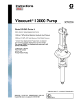
Viscount II 4500 Pump
1500 psi (100 bar, 10 MPa) Maximum Hydraulic Input Pressure
4500 psi (310 bar, 31 MPa) Maximum Working Pressure
Model 221–066, Series B
With Severe-Duty Displacement Pump*
and Quiet Hydraulic Motor
* Severe-Duty displacement pumps have an abrasion
and corrosion-resistant displacement rod and cylinder.
Refer to the Technical Data section of the separate pump
manual for “Wetted Parts” information.
GRACO INC.
P.O. BOX 1441 MINNEAPOLIS, MN
COPYRIGHT 1975, GRACO INC.
Graco Inc. is registered to I.S. EN ISO 9001
55440–1441
Table of Contents
Warnings . . . . . . . . . . . . . . . . . . . . . . . . . . . . . . . . . . . . . . 2
Installation . . . . . . . . . . . . . . . . . . . . . . . . . . . . . . . . . . . . 5
Operation . . . . . . . . . . . . . . . . . . . . . . . . . . . . . . . . . . . . . 8
Maintenance . . . . . . . . . . . . . . . . . . . . . . . . . . . . . . . . . . 10
Troubleshooting . . . . . . . . . . . . . . . . . . . . . . . . . . . . . . . 11
Service . . . . . . . . . . . . . . . . . . . . . . . . . . . . . . . . . . . . . . 12
Parts . . . . . . . . . . . . . . . . . . . . . . . . . . . . . . . . . . . . . . . . 13
Dimensions . . . . . . . . . . . . . . . . . . . . . . . . . . . . . . . . . . .
Mounting holes . . . . . . . . . . . . . . . . . . . . . . . . . . . . . . .
Performance Charts . . . . . . . . . . . . . . . . . . . . . . . . . . .
Technical Data . . . . . . . . . . . . . . . . . . . . . . . . . . . . . . . .
Warranty . . . . . . . . . . . . . . . . . . . . . . . . . . . . . . . . . . . . .
Graco Phone Number . . . . . . . . . . . . . . . . . . . . . . . . . .
14
14
15
15
16
16
Symbols
Warning Symbol
Caution Symbol
WARNING
CAUTION
This symbol alerts you to the possibility of serious
injury or death if you do not follow the instructions.
This symbol alerts you to the possibility of damage to
or destruction of equipment if you do not follow the
instructions.
WARNING
EQUIPMENT MISUSE HAZARD
Equipment misuse can cause the equipment to rupture or malfunction and result in serious injury.
D This equipment is for professional use only.
D Read all instruction manuals, tags, and labels before operating the equipment.
D Use the equipment only for its intended purpose. If you are not sure, call your Graco distributor.
D Do not alter or modify this equipment.
D Check equipment daily. Repair or replace worn or damaged parts immediately.
D Do not exceed the maximum working pressure stated on the equipment or in the Technical Data
for your equipment. Do not exceed the maximum working pressure of the lowest rated component
in your system.
D Use fluids and solvents which are compatible with the equipment wetted parts. Refer to the Technical Data section of all equipment manuals. Read the fluid and solvent manufacturer’s warnings.
D Handle hoses carefully. Do not pull on hoses to move equipment.
D Route hoses away from traffic areas, sharp edges, moving parts, and hot surfaces. Do not expose
Graco hoses to temperatures above 66_C (150_F) or below –40_C (–40_F).
D Wear hearing protection when operating this equipment.
D Do not move or lift pressurized equipment.
D Comply with all applicable local, state, and national fire, electrical, and safety regulations.
WARNING
INJECTION HAZARD
Spray from the gun/valve, leaks or ruptured components can inject fluid into your body and cause extremely serious injury, including the need for amputation. Fluid splashed in the eyes or on the skin can
also cause serious injury.
Fluid injected into the skin might look like just a cut, but it is a serious injury. Get immediate medical attention.
Do not point the gun/valve at anyone or at any part of the body.
Do not put your hand or fingers over the spray tip/valve nozzle.
Do not stop or deflect leaks with your hand, body, glove or rag.
Do not “blow back” fluid; this is not an air spray system.
Always have the tip guard and the trigger guard on the gun/valve when spraying/dispensing.
Be sure the gun/valve trigger safety operates before spraying/dispensing.
Lock the gun/valve trigger safety when you stop spraying/dispensing.
Follow the Pressure Relief Procedure on page 8 if the spray tip clogs and before cleaning,
checking or servicing the equipment.
Tighten all fluid connections before operating the equipment.
Check the hoses, tubes, and couplings daily. Replace worn, damaged, or loose parts immediately.
Permanently coupled hoses cannot be repaired; replace the entire hose.
MOVING PARTS HAZARD
Moving parts can pinch or amputate your fingers.
Keep clear of all moving parts when starting or operating the pump.
Before checking or servicing the equipment, follow the Pressure Relief Procedure on page 8 to
prevent the equipment from starting unexpectedly.
WARNING
FIRE AND EXPLOSION HAZARD
Improper grounding, poor ventilation, open flames or sparks can cause a hazardous condition and result in a fire or explosion and serious injury.
Ground the equipment and the object being sprayed. Refer to Grounding on page 5.
If there is any static sparking or you feel an electric shock while using this equipment, stop spraying/dispensing immediately. Do not use the equipment until you identify and correct the problem.
Provide fresh air ventilation to avoid the buildup of flammable fumes from solvents or the fluid
being sprayed/dispensed.
Keep the spray/dispense area free of debris, including solvent, rags, and gasoline.
Before operating this equipment, electrically disconnect all equipment in the spray/dispense area.
Before operating this equipment, extinguish all open flames or pilot lights in the spray/dispense
area.
Do not smoke in the spray/dispense area.
Do not turn on or off any light switch in the spray/dispense area while spraying/dispensing or while
operating if fumes are present.
Do not operate a gasoline engine in the spray/dispense area.
TOXIC FLUID HAZARD
Hazardous fluid or toxic fumes can cause serious injury or death if splashed in the eyes or on the skin,
inhaled, or swallowed.
Know the specific hazards of the fluid you are using.
Store hazardous fluid in an approved container. Dispose of hazardous fluid according to all local,
state and national guidelines.
Always wear protective eyewear, gloves, clothing and respirator as recommended by the fluid and
solvent manufacturer.
4
307-159
Installation
General Information
4. Spray gun: ground through connection to a properly grounded fluid hose and sprayer.
NOTE: Reference numbers and letters in parentheses
in the text refer to the callouts in the figures and the
parts drawing.
5. Object being sprayed: follow your local code.
NOTE: Always use Genuine Graco Parts and Accessories, available from your Graco distributor.
Grounding
WARNING
FIRE AND EXPLOSION HAZARD
Before operating the pump, ground the
system as explained below. Also read
the section FIRE OR EXPLOSION HAZARD on page 4.
6. Fluid supply container: follow your local code.
7. Solvent pails used when flushing: follow your local
code. Use only metal pails, which are conductive,
placed on a grounded surface. Do not place the
pail on a nonconductive surface, such as paper or
cardboard, which interrupts the grounding continuity.
8. To maintain grounding continuity when flushing or
relieving pressure, hold a metal part of the spray
gun firmly to the side of a grounded metal pail,
then trigger the gun.
1. Pump: use a ground wire and clamp as shown in
Fig. 1. Loosen the grounding lug locknut (W) and
washer (X). Insert one end of a 12 ga (1.5 mm)
minimum ground wire (Y) into the slot in lug (Z)
and tighten the locknut securely. Connect the other
end of the wire to a true earth ground. Order part
number 222–011 Grounding Clamp and Wire.
Z
X
Y
2. Fluid and hydraulic hoses: use only grounded
hoses with a maximum of 500 ft (150 m) combined
hose length to ensure grounding continuity.
3. Hydraulic Power Supply: according to manufacturer’s recommendations.
W
06431
Fig. 1
Installation
E
F
H
J
N
K
C
L
S
G
D
A
R
P
B
T
Q
M
06639
Key
A
B
C
D
E
F
G
H
J
Fluid Hose to Gun
Fluid Drain Valve
Suction Hose
Hydraulic Return Line
Hydraulic Return Line Shutoff Valve
Pressure Gauge
Flow Control Valve
Pressure Reducing Valve
Accumulator
K
L
M
N
P
Q
R
S
T
Drain Line (from pressure reducing valve)
Hydraulic Supply Line
Hydraulic Power Supply
Ground Wire
Wet-Cup
Drain Line (from motor drip pan)
Check Valve
Hydraulic Supply Line Shutoff Valve
Return Line Filter
Fig. 2
Mount the pump to suit the type of installation planned.
Pump dimensions and mounting hole layout are shown
on page 14.
CAUTION
It is very important to keep the hydraulic supply
system clean at all times. Be sure that all hydraulic
fluid lines are absolutely clean. Blow out the lines
with air and flush thoroughly with solvent before
connecting to the hydraulic motor to avoid introducing harmful contaminants into the motor.
6
307-159
Filters
Be sure that your hydraulic power supply is equipped
with a suction filter to the hydraulic pump and a system
return line filter of 10 micron size.
Carefully follow the manufacturer’s recommendations
on reservoir and filter cleaning, and periodic changes
of hydraulic fluid. Use only Graco-approved hydraulic
oil.
Installation
Hydraulic Lines
Operating Temperature
The motor has a 3/4 npt(f) hydraulic oil supply fitting,
and a 1” npt(f) hydraulic oil return fitting. Usa a minimum 1/2 in. ID hydraulic supply line and a minimum
7/8 in. ID, return line.
Keep the hydraulic oil temperature below 130_ F
(54_ C) for maximum pump performance.
On the hydraulic supply side (C), install the following
accessories shown in Fig. 2, using adapters as necessary.
The hydraulic motor is equipped with a drip pan to
collect any leakage that might occur. Connect a 1/4 in.
ID drain hose (Q) to the barbed hose fitting on the drip
pan.
D A shutoff valve (E) isolates the pump for service.
D A fluid pressure gauge (F) to monitor hydraulic oil
pressure to the motor and to avoid overpressurizing
the motor or displacement pump, and a pressureand temperature-compensated flow control
valve (G) to prevent the motor from running too
fast and possibly damaging itself.
D A pressure reducing valve (H), with a drain
line (K) running directly to the hydraulic return
line (D).
D An accumulator (J) to reduce the hammering
effect caused by the motor reversing direction.
D A shutoff valve (E) isolates the pump for service.
CAUTION
Do not exceed 10 gpm (37.8 liter/minute) volume to
avoid pump stalling.
Drip Pan
Drain Valve
Install a high pressure fluid drain valve (B) near the
pump outlet to relieve fluid pressure in the displacement pump and hose during shutdown. See Fig. 2.
WARNING
The fluid drain valve (B) is required in your system
to help reduce the risk of serious injury, including
fluid injection and splashing in the eyes or on the
skin if you are adjusting or repairing any part of the
system. Triggering the gun to relieve pressure may
not be sufficient.
Fluid Lines
Connect a grounded fluid supply line to the 1 in. npt
fluid outlet on the displacement pump.
Attach a suction nose to the 1–1/2 in. npt pump fluid
intake.
Operation
Pressure Relief Procedure
WARNING
INJECTION HAZARD
Fluid under high pressure can be injected through the skin and cause serious injury. To reduce the risk of an injury
from injection, splashing fluid, or moving parts, follow the Pressure Relief Procedure whenever you:
are instructed to relieve the pressure,
stop spraying/dispensing,
check or service any of the system equipment,
or install or clean the spray tips/nozzles.
1. Lock the spray gun or dispensing valve trigger
safety latch and any other equipment safety
latches.
2. Shut off the power supply to the hydraulic motor.
3. Unlock the gun/valve trigger safety, and trigger the
gun into a grounded metal waste container, holding
a metal part of the gun firmly to the side of the
container until pressure is relieved.
Hydraulic Fluid
Check the hydraulic fluid level, and add fluid as necessary to the fill lines before each use.
Wet-Cup
If the pump is not immersed, fill the displacement
pump wet-cup (P) 1/3 full of Graco Throat Seal Liquid
(TSL) or compatible solvent to prevent fluid from drying
on the displacement rod and damaging the pump
packings. See Fig. 2.
Flushing
Flush the pump before using it for the first time to
remove the light oil which was left in after factory
testing to protect the pump from corrosion. Be sure the
solvent used is compatible with the fluid to be sprayed
and the pump wetted parts shown (see manual
307–728). Flush until clean solvent comes from the
gun, or in a circulating system, flush long enough to
clean the entire system.
4. Lock the trigger safety.
5. Open all system drain valves, having a container
ready to catch the drainage.
If you suspect that the spray tip or hose is completely
clogged, or that pressure has not been fully relieved
after following the steps above, very slowly loosen the
tip guard retaining nut or hose end coupling and relieve
pressure gradually, then loosen completely. Now clear
the tip or hose.
8
307-159
WARNING
Be sure the entire system and flushing pails are
properly grounded before flushing. Always use the
lowest possible fluid pressure, and maintain firm
metal to metal contact between the gun and pail to
reduce the risk of static sparking and splashing.
See page 5.
Operation
WARNING
COMPONENT RUPTURE HAZARD
To reduce the risk of overpressurizing
your system, which could cause component rupture and serious injury, never
exceed the specified Maximum Incoming Air Pressure to the pump (see the Technical Data on
page 15).
To prevent overpressurizing the hydraulic motor or
its seals, always shut off the supply line valve (S)
first, then shut off the return line valve (E).
Pump Operation
To operate the pump, turn on the hydraulic power
supply. Open the return line shutoff valve first, then
slowly open the hydraulic supply shutoff valve. Use the
lowest possible pressure to obtain the desired results.
Higher pressures will increase tip wear and pump
wear.
In a direct supply system, the pump will start when the
gun or valve is opened, and stall when it is closed. In a
circulating system, the pump will operate continuously
until the hydraulic power supply is turned off.
WARNING
To reduce the risk of overpressurizing the pump,
which can cause a rupture, fire or explosion and
result in serious injury including fluid injection,
always follow these precautions.
Never exceed 1500 psi (100 bar, 10 MPa), or 3.3
gpm (12.5 liter/min) hydraulic input to the motor.
Never exceed 4500 psi (310 bar, 3.1 MPa) maximum pump outlet pressure.
CAUTION
Do not allow the hydraulic oil temperature to exceed
130 F (54 C). The pump seals will wear faster and
leakage may occur if the pump is operated at higher
oil temperatures.
307-159
9
Maintenance
WARNING
To reduce the risk of serious injury whenever you
are instructed to relieve pressure, always follow the
Pressure Relief Procedure on page 8.
Keep the wet-cup (P) 1/3 filled with Graco Throat Seal
Liquid (TSL)
Check the tightness of the packing nut weekly. Before
adjusting, relieve the pressure. The packing nut
should be tight enough to stop leakage, but no tighter.
Overtightening will compress and damage the packings and result in pump leaking. Place a pin in one of
the holes of the packing nut to adjust it.
Carefully monitor the fluid supply. If the pump empties
the supply container, air will be drawn into the pump,
causing it to run too fast and to be damaged. If the
pump runs too fast, shut it off immediately. Fill the
supply container and prime the pump and hoses to
remove all air, or flush the pump and hoses with a
compatible solvent and leave it filled with an oil-base
solvent or mineral spirits.
Always flush the pump before the fluid can dry in it.
Always stop the pump at the bottom of its stroke to
prevent the fluid from drying on the displacement rod.
Corrosion Protection for Carbon Steel
WARNING
To reduce the risk of serious injury whenever you
are instructed to relieve pressure, always follow the
Pressure Relief Procedure on page 8.
CAUTION
Water, or even moist air, can cause your pump to
corrode. To help prevent corrosion, never leave the
pump filled with water or air. After normal flushing,
flush the pump again with mineral spirits or oil-based
solvent, relieve the pressure, and leave the mineral
spirits in the pump.
Troubleshooting
WARNING
To reduce the risk of serious injury whenever you
are instructed to relieve pressure, always follow the
Pressure Relief Procedure on page 8.
Before servicing this equipment, always make sure to
relieve the pressure.
NOTE: Check all possible problems and solutions
before disassembling the pump.
Problem
Cause
Solution
Pump operates, but output low on
both strokes
Restricted lines or inadequate hydraulic supply
Clear lines; increase hydraulic supply.
Open flow control
Insufficient hydraulic pressure;
Closed or clogged valves, etc.
Open; clean.
Exhausted fluid supply
Refill & reprime, or flush*
Clogged fluid line, valves, etc.
Clear**
Packing nut too tight
Loosen
Loose packing nut or worn packings
Tighten; replace. See manual
307–728
Pump operates, but output low on
down stroke
Held open or worn intake valve
Clear, service. See manual 307–728
Pump operates, but output low on
up stroke
Held open or worn piston or packings
Clear; service. See manual 307–728
Erratic pump operation
Exhausted fluid supply
Refill and reprime, or flush*
Held open or worn intake valve or
piston packings
Clear; service. See manual 307–728
Excessive hydraulic fluid supply volume
Lower
Restricted lines or inadequate hydraulic supply
Clear; increase
Insufficient hydraulic pressure; closed
or clogged valves, etc.
Open, clean
Exhausted fluid supply
Refill and reprime, or flush*
Clogged fluid line, valves, etc.
Clear**
Damaged hydraulic motor
Service. See manual 307–158
Dried fluid seizure of displacement
rod
Service***
Pump fails to operate
* Stop the pump immediately if it is running too fast; check the fluid supply. If empty, refill and reprime the pump
being sure to eliminate all air from the system, or flush the pump and store it with an oil-based solvent, such as
mineral spirits, to prevent corrosion.
** Relieve the pressure, and then disconnect the fluid line. If the pump starts when the hydraulic power is restored, line, etc. is clogged.
*** Always stop the pump at the bottom of its stroke, and keep the packing nut/wet-cup 1/3 full of TSL to help
prevent displacement rod seizure.
Service
Disconnecting the Hydraulic Motor
WARNING
To reduce the risk of serious injury whenever you
are instructed to relieve pressure, always follow the
Pressure Relief Procedure on page 8.
Remove the tie rod lock nuts (3), then unscrew the tie
rods (6) from the hydraulic motor base. See the parts
drawing on page 13.
See separate instruction manual 307–158 for hydraulic
motor service instructions, and 307–728 for the displacement pump.
Relieve the pressure.
Close the hydraulic supply line shutoff valve first, and
then the return line shutoff valve. Disconnect the
hydraulic supply, return, and drain lines from the motor.
Remove the cotter pin (1) and unscrew the connecting
rod coupling nut (7). See the Parts Drawing on
page 13.
When reconnecting the motor to the displacement
pump, be sure the pump outlet is 90_ counterclockwise
(looking at the top of the motor) from the motor inlet
and outlet. Refer to the illustration on the front cover.
Use locking compound and tighten the tie rods (6)
securely into the hydraulic motor base. torquing the
40–50 ft-lb (54–68 NSm). Torque the tie rod locknuts
(3) to 40–50 ft-lb (54–68 NSm).
Parts
1
Torque to 40–50 ft-lb (54–68 NSm)
34
Ref.
No.
Part No.
Description
1
100–103
3
4
5
6
7
8
9
11
101–712
101–936
158–674
167–911
168–210
168–211
168–212
217–527
34
221–168
35
36
158–586
203–916
37
38*
39
40
41
42
203–921
101–454
151–220
160–494
160–516
162–289
PIN, cotter; 0.125” (3.18 mm) x
1.50” (38.1 mm); steel
NUT, lock; 5/8–11
NUT, hex jam; 3/4–10
O-RING; nitrile rubber
ROD, tie
NUT, coupling
COUPLING, connecting rod
ROD, connecting
DISPLACEMENT PUMP
See manual 307–728 for parts
HYDRAULIC MOTOR
See manual 307–158 for parts
BUSHING, pipe
CHECK VALVE ASSEMBLY
Includes items 37–42
. SEAT
. BALL, steel; 5/8” dia.
. SPRING, compression
. HOUSING
. O-RING; VitonR
. PLUG
Qty.
2
3
1
1
3
1
1
1
1
1
1
1
1
1
1
1
1
1
*Recommended Tool Box spare parts. Keep these spare
parts on hand to reduce down time.
8
1
VitonR is a registered trademark of the DuPont Company.
7
5
6
1
3
1
9
4
1
37
11
38*
41
35
06637
40
39
42
Dimensions
Mounting Hole
Layout
Gasket
161–806
1” npt(f) Outlet
3/4 npt(f) Inlet
45.8” (1163 mm)
4” (102 mm)
Four .437” (11.1 mm)
holes on 10.5”
(267 mm) bolt circle
9.75”
(247.7 mm)
1.38”
(34.9 mm) R
90
45
06595
1” npt(f)
20.9” (531 mm)
1–1/2” npt(f)
06638
Accessories
HYDRAULIC FLUID, Graco-Approved
207–428 1 gallon (3.8 liter)
169–236 5 gallons (19 liters)
14
307-159
POLYETHYLENE TUBE 054–106
0.25 in. (6.4 mm) ID; 0.375 in. (9.5 mm) OD.
Connect to barbed hose fitting on hydraulic motor drip
pan. Order desired length.
Technical Data
Maximum hydraulic input pressure . . . . . . . . . . . . . . . . . . . . . . . . . . . . . . . . . . . . . . . . . . . . 1500 psi (100 bar, 10.0 MPa)
Maximum pump output pressure . . . . . . . . . . . . . . . . . . . . . . . . . . . . . . . . . . . . . . . . . . . . . . 4500 psi (310 bar, 31.0 MPa)
Maximum recommended pump speed . . . . . . . . . . . . . . . . . . . . . . . . . . 50 cycles per minute – 3.3 gpm (12.5 liter/min)
Hydraulic fluid consumption . . . . . . . . . . . . . . . . . . . . . . . . . . . . . . . . . . . . . . . . . . . . . . . . . . . . . 0.2 gal (0.76 liter) per cycle
Wetted parts . . . . . . . . . . . . . . . . . . . . . . . . . . . . . . . . . . . . . . . . . . . . . . . . . . . . . . . . . . . . . . . . . . . . . . . See manual 307–728
VitonR is a registered trademark of the Loctite Corporation.
Pump Performance Charts
Pump Pressure Developed
Hydraulic
Input Pressure
Pump Outlet
Pressure
Pump Output
Pump
Speed
Hydraulic
Fluid Required
Pump
Output
(Cycles/min)
gpm
liter/min
gpm
liter/min
(41 bar, 4.1 MPa)
5
1.0
3.8
0.33
1.1
(62 bar, 6.2 MPa)
10
2.0
7.6
0.66
2.5
15
3.0
11.4
0.99
3.7
(104 bar, 10.4 MPa)
20
4.0
15.1
1.32
5.0
(124 bar, 12.4 MPa)
25
5.0
18.9
1.65
6.3
30
6.0
22.7
1.98
7.5
(166 bar, 16.6 MPa)
35
7.0
26.5
2.31
8.7
(187 bar, 18.7 MPa)
40
8.0
30.3
2.65
10.0
45
9.0
34.1
2.97
11.2
50
10.0
37.8
3.30
12.5
100 psi
(7 bar, .7 MPa)
300 psi
(21 bar, 2.1 MPa)
200 psi
( 14 bar, 1.4 MPa)
600 psi
300 psi
( 21 bar, 2.1 MPa)
900 psi
400 psi
(28 bar, 2.8 MPa)
1200 psi
(83 bar, 8.3 MPa)
500 psi
(34 bar, 3.4 MPa)
1500 psi
600 psi
(41 bar, 4.1 MPa)
1800 psi
700 psi
(48 bar, 4.8 MPa)
2100 psi
(145 bar, 14.5 MPa)
800 psi
(55 bar, 5.5 MPa)
2400 psi
900 psi
(62 bar, 6.2 MPa)
2700 psi
1000 psi
(69 bar, 6.9 MPa)
3000 psi
(208 bar, 20.8 MPa)
1100 psi
(76 bar, 7.6 MPa)
3300 psi
(229 bar, 22.9 MPa)
1200 psi
(83 bar, 8.3 MPa)
3600 psi
(250 bar, 25.0 MPa)
1300 psi
(90 bar, 9.0 MPa)
3900 psi
(271 bar, 27.1 MPa)
1400 psi
(97 bar, 9.7 MPa)
4200 psi
(292 bar, 29.2 MPa)
1500 psi
(104 bar, 10.4 MPa)
4500 psi
(313 bar. 31.3 MPa)
Manual Change Summary
The following changes have been added to this manual since the last revision:
D The entire manual was updated electronically.
The Graco Warranty and Disclaimers
WARRANTY
Graco warrants all equipment listed in this manual which is manufactured by Graco and bearing its name to be free from defects
in material and workmanship on the date of sale by an authorized Graco distributor to the original purchaser for use. Graco will,
for a period of twelve months from the date of sale, repair or replace any part of the equipment determined by Graco to be defective. This warranty applies only when the equipment is installed, operated and maintained in accordance with Graco’s written recommendations.
This warranty does not cover, and Graco shall not be liable for general wear and tear, or any malfunction, damage or wear
caused by faulty installation, misapplication, abrasion, corrosion, inadequate or improper maintenance, negligence, accident,
tampering, or substitution of non-Graco component parts. Nor shall Graco be liable for malfunction, damage or wear caused by
the incompatibility of Graco equipment with structures, accessories, equipment or materials not supplied by Graco, or the improper design, manufacture, installation, operation or maintenance of structures, accessories, equipment or materials not supplied by Graco.
This warranty is conditioned upon the prepaid return of the equipment claimed to be defective to an authorized Graco distributor
for verification of the claimed defect. If the claimed defect is verified, Graco will repair or replace free of charge any defective
parts. The equipment will be returned to the original purchaser transportation prepaid. If inspection of the equipment does not
disclose any defect in material or workmanship, repairs will be made at a reasonable charge, which charges may include the
costs of parts, labor, and transportation.
THIS WARRANTY IS EXCLUSIVE, AND IS IN LIEU OF ANY OTHER WARRANTIES, EXPRESS OR IMPLIED, INCLUDING
BUT NOT LIMITED TO WARRANTY OF MERCHANTABILITY OR WARRANTY OF FITNESS FOR A PARTICULAR PURPOSE.
Graco’s sole obligation and buyer’s sole remedy for any breach of warranty shall be as set forth above. The buyer agrees that no
other remedy (including, but not limited to, incidental or consequential damages for lost profits, lost sales, injury to person or property, or any other incidental or consequential loss) shall be available. Any action for breach of warranty must be brought within two
(2) years of the date of sale.
GRACO MAKES NO WARRANTY, AND DISCLAIMS ALL IMPLIED WARRANTIES OF MERCHANTABILITY AND FITNESS
FOR A PARTICULAR PURPOSE IN CONNECTION WITH ACCESSORIES, EQUIPMENT, MATERIALS, OR COMPONENTS
SOLD BUT NOT MANUFACTURED BY GRACO. These items sold, but not manufactured by Graco (such as electric motors,
switches, hose, etc.) are subject to the warranty, if any, of their manufacturer. Graco will provide purchaser with reasonable assistance in making any claim for breach of these warranties.
For Sales to Canadian Customers:
Except as expressly stated herein, Graco makers no representations, warranties or conditions, express, implied or collateral, concerning any goods or services sold, and GRACO SHALL NOT BE LIABLE IN ANY MANNER FOR any other representation,
warranty or condition of any kind, whether arising by operation of law or otherwise, including but not limited to, WARRANTIES OF
MERCHANTABLE QUALITY OR FITNESS FOR A PARTICULAR PURPOSE.
LIMITATION OF LIABILITY
In no event will Graco be liable for indirect, incidental, special or consequential damages resulting from Graco supplying equipment hereunder, or for the furnishing, performance, or use of any products or other goods sold hereto, whether due to a breach of
contract, breach of warranty, the negligence of Graco, or otherwise.
Graco Phone Number
TO PLACE AN ORDER, contact your Graco distributor, or call this number to identify the distributor closest to you:
1–800–367–4023 Toll Free.
All written and visual information contained in this document reflects the latest product information available at the time of
publication. Graco reserves the right to make changes at any time without notice.
Sales Offices: Atlanta, Chicago, Detroit, Los Angeles
Foreign Offices: Belgium, Canada, England, Korea, Switzerland, France, Germany, Hong Kong, Japan
GRACO INC.
P.O. BOX 1441 MINNEAPOLIS, MN
55440–1441
PRINTED IN U.S.A. 307–159 May 1975, Revised August 1996
16
307-159