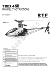
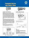
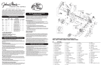
1
GILSJ
JN MIXERS
MORTAR-PLASTER MIXER
MODEL: 600MP
OPERATOR’S GUIDE & PARTS MANUAL
GILSJ
J N MIXERS
BY
4343 Easton Road · St. Joseph, MO 64503
816-233-4840 · 800-253-3676
Fax 816-233-4624 · 888-253-3676
E-Mail: [email protected]
Web Address: www.cleform.com
INTRODUCTION
This operator’s manual has been prepared to provide the information you need to
correctly operated and maintain your mixer. For maximum satisfaction, carefully read
and follow the instructions in this manual. Should you need repair parts or service, refer
to the parts breakdown on pages 14 through 25.
Information regarding operation and maintenance of the factory-installed engine or motor
can be found in a separate engine/motor owner’s manual supplied with the mixer. The
manual prepared by the engine/motor manufacturer gives you the information necessary
regarding engine adjustments, operation and maintenance. Should any questions arise
concerning engine operation or service, contact the nearest engine/motor repair facility or
dealer. For dealers in your area, consult the Yellow Pages under “Engines-Gasoline” or
“Motors-Electric”.
Be sure safety precautions are observed. Read and follow all safety and operating
instructions in this operator’s manual.
The replacement of any part on this product by other than the manufacturer’s authorized
replacement part may adversely affect the performance, durability, or safety of the
product.
The manufacturer reserves the right to make changes on, or add improvements to its
product at any time reserves the right to decide, upon its sole discretion and at any time,
to discontinue a product.
NOTICE: Record the model and serial numbers of your unit (located on the
nameplate) in the spaces provided below. Engine model, type and code numbers are
located on the engine blower housing, cylinder head or back plate.
PRODUCT MODEL NUMBER: ________________________________
PRODUCT SERIAL NUMBER: ________________________________
ENGINE/MOTOR MODEL NUMBER: __________________________
ENGINE/MOTOR CODE NUMBER: ____________________________
PURCHASE DATE: _________________________________________
DEALER PURCHASED FROM: _______________________________
DEALER ADDRESS: ________________________________________
DEALER PHONE NUMBER: _________________________________
1
TABLE OF CONTENTS
1. SAFETY PRECAUTIONS . . . . . . . . . . . . . . . . . . . . . . . . . . . . . 3
2. ASSEMBLY AND PREOPERATIONAL CHECKS . . . . . . . 4
3. CONTROLS AND OPERATION
Clutch Control Lever . . . . . . . . . . . . . . . . . . . . . . . . . . . . 5
Tow Pole Assembly . . . . . . . . . . . . . . . . . . . . . . . . . . . . . .6
Safety Chains . . . . . . . . . . . . . . . . . . . . . . . . . . . . . . . . . . 6
4. MIXER TRANSPORT . . . . . . . . . . . . . . . . . . . . . . . . . . . . . . . . 7
5. MIXER OPERATION
Starting the Mixer . . . . . . . . . . . . . . . . . . . . . . . . . . . . . . . 7
Extension Cords for Electric Motors . . . . . . . . . . . . . . . . .7
Loading the Mixer . . . . . . . . . . . . . . . . . . . . . . . . . . . . . . . 8
Discharging the Mixer . . . . . . . . . . . . . . . . . . . . . . . . . . . .8
Cleaning . . . . . . . . . . . . . . . . . . . . . . . . . . . . . . . . . . . . . . . 8
Trouble Shooting Guide for MP Mixers . . . . . . . . . . . . . . .9
6. OPERATING GUIDELINES
Masonry Construction Guidelines . . . . . . . . . . . . . . . . . . .10
7. LUBRICATION
Drum Seal Housings . . . . . . . . . . . . . . . . . . . . . . . . . . . . . . 10
Mixing Shaft Bearings . . . . . . . . . . . . . . . . . . . . . . . . . . . . .11
Wheel Bearings . . . . . . . . . . . .. . . . . . . . . . . . . . . . . . . . . . 11
Drum Shaft Bearing Hangers . . . . . . . . . . . . . . . . . . . . . . . 11
Engine/Motor . . . . . . . . . . . . . . . . . . . . . . . . . . . . . . . . . . . 11
8. ADJUSTMENT
Rubber Wiper Blades . . . . . . . . . . . . . . . . . . . . . . . . . . . . . 12
Engine/Motor Drive . . . . . . . . . . . . . . . . . . . . . . . . . . . . . . 12
9. STORAGE . . . . . . . . . . . . . . . . . . . . . . . . . . . . . . . . . . . . . . . . . .13
10. PARTS LISTS AND POWER OPTIONS
Drum and Drive . . . . . . . . . . . . . . . . . . . . . . . . . . . . . . . . . 14-15
Mixing Blades . . . . . . . . . . . . . . . . . . . . . . . . . . . . . . . . . . 16-17
Engine Housing Assembly . . . . . . . . . . . . . . . . . . . . . . . . .18-19
Frame Drive and Clutch Control . . . . . . . . . . . . . . . . . . . . 20-21
Engine and Power Options . . . . . . . . . . . . . . . . . . . . . . . . .22-25
2
1 – SAFETY PRECAUTIONS
THE FOLLOWING PRECAUTIONS ARE SUGGESTED TO HELP PREVENT
ACCIDENTS. A CAREFUL OPERATOR IS THE BEST OPERATOR. MOST
ACCIDENTS CAN BE AVOIDED BY OBSERVING CERTAIN PRECAUTIONS.
READ AND PRACTICE THE FOLLOWING PRECAUTIONS BEFORE
OPERATING THIS EQUIPMENT TO HELP PREVENT ACCIDENTS.
EQUIPMENT SHOULD BE OPERATED ONLY BY THOSE WHO ARE
RESPONSIBLE AND HAVE BEEN PROPERLY INSTRUCTED.
Read all operating and maintenance instruction before operating or servicing
the mixer. Test run the empty unit prior to actual use.
A mixer is only as safe as its operator. Give complete and undivided attention
to the operations of the mixer.
Know how to stop the mixer and engine/motor instantly in emergency
situations.
Always keep all guard and safety devices and labels attached and in place
before operating mixer. Close engine housing during mixer operation.
Keep inexperienced and unauthorized people away from the mixer at all times.
Never leave the mixer unattended when it is running
Shut off engine or disconnect electric power before making repairs or
adjustments. NEVER REACH INTO DRUM OR PLACE TOOLS INTO
THE DRUM WHILE THE MIXER IS RUNNING.
Do not overfill- -do not attempt to exceed the mixer’s rated capacity.
Do not refuel the engine when it is hot or running.
Do not smoke while refueling the engine.
Block mixer wheels when in operation.
Keep the mixer well maintained and in good operating condition. Check
periodically for loose or missing hardware.
Avoid loose clothing that could get caught in moving parts or on control levers.
KEEP HANDS AND FEET AWAY FROM MOVING PARTS.
3
Never charge or fill the unit prior to starting the mixing blades as an overload
encountered in starting a loaded unit could damage the engine/motor or drive
components.
Connect safety chains as instructed when towing the mixer. Connect only to
correct hitch or coupler.
Keep warning, caution and safety instruction labels clean and in good condition.
Replace missing, damaged or illegible labels.
2 – ASSEMBLY AND PRO-OPERATIONAL CHECKS
The only assembly required on this mixer is the installation of the drum tilt handle.
Remove the handle from the bag shipped in the drum and install, referring to parts
list Figure 5, item numbers 7, 18, 20 and 21 for proper assembly.
The following steps should be taken prior to placing the mixer in use:
1. The operator must be familiar with the location and operation of all controls.
2. Check the crankcase oil level on gasoline powered units, and fill the fuel tank
before starting.
3. Check for free rotation of the mixer blade shaft by rotating the drum through
one complete dump-charge-dump cycle. Make sure no foreign objects or
tools are in drum before starting engine/motor.
4. Start engine/motor, slowly engage the drum drive and check for smooth
operation of the mixer blade shaft and drive.
5. Move the clutch lever through several cycles to assure correct clutch
operation.
4
3 – CONTROLS AND OPERATIONS
1. The mixing paddles feature adjustable rubber wipers and steel backing plates.
Paddles are factory preset for appropriate drum wrap clearance. If adjustment is
required, proceed as follows:
A. Loosen the wiper attaching hardware and move the wiper outward to
maintain contact with the drum but without folding over when in
operation.
B. After adjustment, turn the mixer arms one full turn manually to check
clearance and eliminate the possibility of wiper back plates contacting the
drum.
2. Read through the manual for all operation, adjustment and maintenance
instructions. Be sure all engine/motor and drive system operation instructions are
followed as outlines.
3. All nuts and cap screws should be checked and tightened during the first two (2)
hours of use. Periodic checks should be made thereafter.
CLUTCH CONTROL LEVER
This control is located in front of the mixing drum on the mixer leg. SEE FIGURE 1.
This control engages and disengages the drive to the mixing blades.
TO ENGAGE: Position lever in line with the mixer frame (12 o’clock position). Lever
is held in the engage position by the over-center action of the linkage.
TO DISENGAGE: Push lever down (counter-clock-wise) to the 9 o’clock position.
Lever is spring loaded to hold it in the disengaged position.
5
TOW POLE ASSEMBLY
The tow pole assembly is located on the front of the mixer and is used for transport only.
For transport, pull the tow pole assembly out, line up the hold and insert the L-shaped pin
through holes.
When operating the mixer, pull the L-shaped pin out of the hole and push tow pole
assembly all the way in. Line up the holes and insert the L-shaped pin through the holes.
SAFTEY CHAINS
For transporting the mixer, slide the tow pole out as far as possible and insert the locking
pin. When operating the mixer, slide the tow pole in and lock it in place.
Make sure drum is locked in position and engine housing is closed and secured.
1. Cross the chains under the tow pole to prevent the tow pole from dropping to the
ground if the mixer comes loose.
2. Pass chain around a frame member or secure bumper iron and hook it back to
itself for strongest attachment. If the chain hook is attached to a frame member or
bumper iron or hole, it may slip off or the hook straightened out if the mixer
comes loose. Attach chains securely.
3. Allow only enough slack in chains to permit proper turning of vehicles. Do not
let chains drag on ground, or to be drawn up too tight. Slack length should hold
tow pole and front leg off the ground with the mixer loose. (Fig. 2)
NOTE: SAFETY CHAIN LENGTH MAY NEED TO BE ALTERED FOR
PROPER CONNECTION TO TOW VEHICLE. REPOSITION HOOKS, DO NOT
CUT CHAIN.
6
4 – MIXER TRANSPORT
1. Secure drum by engaging drum lock.
2. Secure all moveable parts, including the rear housing.
3. Secure tow pole coupler to vehicle and attach safety chains and hooks. (See
FIGURE 2, Safety Chains).
A. Pintle type couplers require the appropriate tow vehicle coupler retainer.
B. Match ball coupler size exactly with hitch ball.
5 – OPERATING THE MIXER
STARTING THE MIXER
Start the mixer engine/motor. Refer to the engine/motor manual for proper starting
procedures.
Prior to engaging clutch, lift drum latch from between transport lock blocks. Pull drum
to dump position and lower drum latch to horizontal position. Return drum to operating
position with transport lock block resting against drum latch lever. (Note: Rotation of
paddles will hold drum into drum latch lever. SEE CAUTION DECAL ON MIXING
DRUM)
When the engine/motor is warmed up and is running smoothly, move the control lever to
the engaged position.
EXTENSION CORDS FOR ELECTRIC MOTORS
The following size extension cords should be used: length of cord, upt to 100 ft.-14 gauge
wire; up to 200 feet-12 gauge wire; up to 300 feet-10 gauge wire; up to 400 feet-8 gauge
wire.
NOTE: Extension cord must be a 3-wire power cord and 3-wire power plug that is
approved for outdoor use. When connecting the power cord, always connect cord to
motor first and then plug into a grounded receptacle. When disconnecting the
power cord, always unplug the grounded receptacle first.
7
LOADING THE MIXER
When the mixing blades are rotating, pour the required amount of water into the drum,
then add cement, sand and lime.
The desired mixing speed is 33 RPM
DISCHARGING THE MIXER
Allow the entire mixture to mix for one (1) full minute. DO NOT STOP MIXER FROM
ROTATING. Hold the tilt handle and disengage the drum lock. Dump mortar to the side
by pulling the tilt lever downward.
After the mixture is dumped, return the drum to the operating position and engage drum
lock.
CLEANING
To achieve satisfactory performance from the mixer, it is essential to give the drum
reasonable care. Clean the mixer after each use, before the mortar dries and becomes
hard. Never permit mortar to harden on either the inside or outside of the drum. Do not
pound or dent the drum as this impairs mixing efficiency and can cause spot wear on the
drum surface. Spray the entire unit off after each use.
8
TROUBLE SHOOTING GUIDE FOR MP MIXERS.
ENGINE WON’T START:
1. Check for sufficient fuel.
2. Check oil level (some engines have an oil alert, preventing the engine from starting
when oil level is low)
3. Was engine choked when starting?
4. Is engine flooded?
5. Check spark plug. (Clean and check gap).
6. If engine still won’t start, take to service center.
BELT DRIVEN MODELS:
1. Check condition of belts, replace if necessary.
2. Check for oil or grease on belts as well as for loose belts.
3. Adjust set screw under engine base down until belts are tight.
TRANSMISSION DRIVEN MODELS.
CLUTCH SLIPS:
1. Remove spark plug wire.
2. Remove side cover on transmission.
3. Loosen set screw on clutch and adjust clutch clockwise a couple of notches at a time
until paddles turn and have a firm pressure on the clutch handle.
TRANSMISSION TURNS BUT PADDLE ARMS WON’T:
1. Check if shear bolt on coupler is broken and has fallen out.
HYDRAULIC DRIVEN MODELS.
PADDLE ARMS WON’T TURN:
1. Check if clutch rod has been bent or broken.
2. Check if flow control valve moves in forward position.
IF VALVE DOES NOT GO INTO FORWARD POSTION CHECK THE
FOLLOWING:
1. Check if linkages are free.
2. Remove stem set screw (Fig 1) and put a few drops of oil in stem.
3. Replace set screw but do not overtighten.
PADDLE ARMS STOP WHEN DRUM IS FILLED:
1. Remove cap (Fig 2) and set pressure up by tightening threaded screw with allen
wrench no more than ¼ turn at a time. Valve pressure is set at 1500 psi at factory.
Each ¼ turn will increase the pressure by 250 psi. After each ¼ turn check to see if
paddles turn (CAUTION) maximum pressure of valve is 3000 psi.
REVERSE TOO FAST OR TOO SLOW:
1. Loosen set screw on knob (Fig. 3)
2. Turn knob a small amount at a time clockwise to slow movement and
counterclockwise to speed up movement
9
6 – OPERATING GUIDELINES
MASONRY CONSTRUCTION GUIDELINES
The strength and durability of brick masonry depends upon the quality of the brick, the
quality of the mortar and the workmanship in laying. The strength also depends upon
adequate bond and the shape of the masonry unit.
Brick quality – Characteristics are hardness and density. Brick for masonry which is
exposed to weather or where strength is desired should have a crushing strength of not
less than 2500 PSI.
Laying and bonding – Brick should be laid in a full bed of mortar and shoved laterally
into place to secure solid bearing, a bed of even thickness, and to fill the vertical joints.
Brick should be thoroughly wet before laying, except in freezing weather. Bricks laid
with the long dimension parallel to the face of the work are called stretches,
perpendicular to the face are called headers. Bats (chalk bricks) should not be used
except where necessary to make corners or to form patterns on the face of the walls.
Walls are bonded or tied together longitudinally by overlapping stretches in successive
courses. Transverse bond is obtained by making every sixth course headers with the
headers themselves overlapping in successive courses in the interior of thick walls.
Mortars – Mortar composition is dependent on the structural use of the masonry unit. It
is also dependent upon grade, weather exposure and climactic condition. Consult you
brick or block supplier, the ACI (American Concrete Institute) Manual of Concrete
Practices or your local building codes for the proper mortar selection for each application
form more information.
7 – LUBRICATION
DRUM SEAL HOUSINGS
Drum seals are provided on each end of the drum where the mixing shaft passes through
to the bearings. It is important to pump grease into the housings through use to retain
seal efficiency. Use enough grease to flush out old grease and carry away any grit. Use
lithium based grade 2 multi-purpose grease. SEE FIGURE 3
10
MIXING SHAFT BEARINGS
The mixing shaft bearings are permanently factory sealed and lubricated, and should not
require further service.
DRUM SHAFT BEARING HANGERS
Drum bearing hangers are located on each side of the drum, and are equipped with grease
fittings. These bearings should be lubricated once each week with lithium based grade 2
multi-purpose grease. SEE FIGURE 3
ENGINE/MOTOR
Refer to the engine/motor operating instructions for all maintenance and lubrication
instructions and requirements.
WHEEL BEARINGS
Wheel bearings should be packed once a year. Thoroughly clean old lubricant from the
bearings, hub and spindles before repacking. Pack bearings only one-half to two-thirds
full with grease to prevent overheating. Use no. 2 wheel bearing grease.
JACK SHAFT BEARINGS
Pillow block style bearing are used on the drive train counter-shaft. See Drum Seal
Housing, Lubrication Guidelines for more information. See Figure 4 for bearing
locations.
11
8 – ADJUSTMENT
RUBBER WIPER BLADES
Adjust rubber wipers so they fit snugly against the drum but not to the point that they fold
over when the blades rotate.
ENGINE/MOTOR DRIVE
SEE FIGURE 4.
1. Align pulleys correctly
2. Tighten locking collars in the direction of rotation and tighten setscrews.
3. Adjust tension on the engine belt as follows:
A. Place clutch lever in the engaged (drive) position.
B. Move the engine/motor to tighten the belt until the engine plate is slightly
above the horizontal position (about 1-2 degrees). Tighten engine/motor
securely.
4. Adjust belt fingers so they do not touch the belt when the drive is engaged, but
must allow disengagement of the belt when the drive is disengaged.
5. Adjust bull gear for minimum clearance of 3/16 inch from the pillow block stand
and tighten both setscrews.
12
9 – STORAGE
For short term storage, clean the mixer and store in a dry place. If the mixer is not to
be used for an extended period of time, service the mixer completely and store in a
dry place.
1. Refer to the engine/motor instructions for storage instructions.
2. Cover exposed metal surfaces with a thin coat of SAE 30 weight engine oil.
3. Lubricate per instructions outlined in the LUBRICATION section.
13
14
Concrete Mixer Parts List
REF NO. PART NO. DESCRIPTION
QTY
DRUM & DRIVE
1
232255
2
1031
3
214837
4
5079
5
5207
6
232392
7
245704
8
5771
9
245349
10
5772
11
5773
12
5776
13
245258
14
5777
15
*70343
16
*70430
17
*71259
18
*70258
19
*70563
20
*70553
21
*70649
22
*70655
23
*70643
24
*71018
25
*70073
26
*70069
27
*70429
28
*70631
29
1183
* LOCAL SOURCE
Bearing Hanger
Grease Fitting
Gear
Drum Sheel Assembly
Grill Assembly
Bearing Support Assembly
Drum Tilt Lever
Drum Seal
Houseing, Seal
O-ring Seal Clamp
O-Ring
Bearing, Drum shaft
Drum Shaft
Locking Collar
Capscrew, Hex Hd 1/2-13 x 1-1/2 GR 5
Capscrew, Flat Hd 3/8-16 x 1 1/4
Capscrew, Hex Hd 1/4-28 x 3/4 GR 5
Capscrew, Hex Hd 3/8-16 x 2 GR 5
Nut, Hex 1/2-13
Nut, Hex 3/8-16
Washer, 3/8 Spring Lock
Washer, 1/2 Spring Lock
Washer, 1/4 Spring Lock
Key, Square 5/16 x 2
Setscrew, Sq Hd Cup Pt 1/2-13 x 1
Setscrew, Sq Hd Cup Pt 1/2-13 x 1 1/4
Capscrew, Flat Hd 3/8-16 x 1
Nut, Cone Lock 3/8-16
Grip, Drum Tilt Lever
15
2
4
1
1
1
2
1
2
2
2
2
2
1
2
4
8
6
4
4
18
20
4
6
1
1
1
8
2
1
16
Concrete Mixer Parts List
MIXING BLADES
REF NO. PART NO. DESCRIPTION
QTY
1
245711 Mixing Arm Assembly, Tow End
2
2
245709 Mixing Arm Assembly, Engine End
2
3
245705 MixingArm Cap
4
4
5235 Drum Wrap Wiper
4
5
5234 Wrap Wiper Backing Plate
4
6
5230 End Wiper Backing Plate
2
7
5231 Drum End Wiper
2
8
*70343 Capscrew, Hex HD 1/2-13 x 1 1/2 Gr 5
10
9
*70157 Capscrew, Hex HD 5/16-18 x 1 1/4 Gr 5
8
10
*70563 Nut, Hex 1/2-13
10
11
*70549 Nut, Hex 5/16-18
12
12
*70655 Washer, 1/2 Spring Lock
10
13
*70646 Washer, 5/16 Spring Lock
12
14
245708 Side Arm Assembly, Tow End
1
15
245706 Side Arm Assembly, Engine End
1
16
*70164 Capscrew, Hex HD 5/16-18 x 1 1/2 Gr 5
4
17
*70701 Washer, 5/16 Flat
16
*Local Source
17
18
Concrete Mixer Parts List
ENGINE HOUSING AND AXLE
REF NO. PART NO. DESCRIPTION
1
245712 Engine Housing Assembly w/decals
2
245701 Housing Base Assembly
3
32082 Reflector
4
232623 T-Handle Latch
5
5402 Handle, Engine Housing
6
220521 Rivet, Handle
7
223590 Rubber Bumper
8
232614 Housing Base Front Plate
9
213297 Screw, Thread Forming 5/16-18 x 1/2
10
*29065 Screw, Sheet Metal #10-24 x 3/8
11
232299 Axle Assembly
12
38565 Hub Assembly (includes:)
13
1046
Bearing Cup
14
1045
Bearing Cone
15
5037
Hub Cap
16
38567
Lug Nut
17
19981
Seal
18
245306 Axle Support Assembly
20
38569 Wheel and Tire Assembly
(Standard for MP 600)
38570 Wheel
29044 Tire, 4.80-12
10631 Valve Stem w/Cap
20
232385 Wheel and Tire Assembly
(Optional for MP 600)
232386 Wheel
232387 Tire, A78-13
10631 Valve Stem w/cap
21
*70339 Capscrew, Hex Hd 1/2-13 x 1 1/4 Gr 5
22
*70143 Capscrew, Hex Hd 5/16-18 x 3/4 Gr 5
23
*70563 Nut, Hex 1/2-13
24
*70942 Nut, 5/16-18 KEPS
25
*70610 Nut, Hex 10-24 KEPS
26
*70386 Screw, Rd Hd Machine 10-24 x 1/2
27
*70655 Washer, 1/2 Spring Lock
28
*70646 Washer, 5/16 Spring Lock
29
*70701 Washer, 5/16 Flat
30
*70727 Pin, Cotter 1/8 x 1 3/4
31
*70620 Nut, Hex Castle 3/4-16
32
*70713 Washer, 3/4 Flat
33
69500 Kit, Spring Axle (option) includes
34
245550 Bracket, Spring Mount RH
35
245549 Bracket, Spring Mount LH
36
232496 Spring
37
*70343 Capscrew, Hex Hd 1/2-13 x 1 1/2 Gr 5
38
*70563 Nut, Hex 1/2-13
39
*70655 Washer, 1/2 Spring Lock
*-Local Source
19
QTY
1
1
2
2
1
4
4
1
6
4
1
2
4
4
2
10
2
2
2
2
2
2
2
2
8
6
8
4
4
4
8
2
10
2
2
2
1
1
1
2
12
12
12
20
Concrete Mixer Parts List
FRAME, DRIVE AND CLUTCH CONTROL
REF NO. PART NO. DESCRIPTION
1
245265 Frame, Engine and Drive Support
2
245281 Frame Assembly
3
232276 Pin and Chain Assembly
4
*70731 Pin, Cotter 3/16 x 1
5
*2776 Spring Clip
6
232301 Tow Pole Assembly Pintle (std)
7
*71215 Capscrew, Hex Hd 1/2-13 x 3 1/4 Gr 5
8
245426 Handle, Drum Lock
9
36282 Grip Handle
10
*70343 Capscrew, Hex Hd 1/2-13 x 1 1/2 Gr 5
11
*70581 Nut, 1/2-13 Jam
12
*70068 Setscrew, Sq Hd 1/2-13 x 3
13
*70707 Washer, 1/2 Flat
14
5242 Shaft, Pinion
15
5239 Gear, Pinion
16
5082 Bearing, Pillow Block
17
*70804 Key, 1/4 Sq x 2
18
*70498 Setscrew, Soc Hd 5/16-18 x 1/4 Cup Pt
19
Pulley, Driven (see ref #18, Fig 11A)
20
245263 Shaft, Clutch Control
21
245264 Link, 3/8 and 5/8 holes
22
245328 Link, 3/8 and 1/2 holes
23
232263 Link, Clutch 6 inch
24
*70981 Pin, 3/16 x 1 3/8 Roll
25
245316 Clutch Rod Sub-Assembly
26
211689 Roller, Clutch
27
*70705 Washer, 7/16 Flat
28
232266 Spring, Overcenter
29
*70254 Capscrew, Hex Hd 3/8-16 x 1 3/4 Gr 5
30
*70631 Nut, 3/8-16 Cone Lock
31
*70563 Nut, 1/2-13
32
*15589 Washer, 3/8 Flat Thick 7/8 O.D.
33
*70649 Washer, 3/8 Spring Lock
34
*70553 Nut, Hex 3/8-16
35
245338 Clamp, Frame
36
*70655 Washer, 1/2 Spring Lock
*-Local Source
21
QTY
1
1
1
1
1
1
1
1
2
1
1
1
1
1
1
2
2
4
1
1
1
1
2
1
1
2
1
6
2
5
8
6
4
2
4
22
Concrete Mixer Parts List
ENGINE AND POWER OPTIONS
REF NO. PART NO.
1
232412
2
245339
3
*70631
4
*70703
5
232548
6
*70258
7
*70553
8
*70649
9
*23156
10
*71404
11
*70803
12
*70498
13
*70451
DESCRIPTION
Belt Guide, Upper
Belt Guide, Lower (Angled Bracket)
Nut, Hex 3/8-16 Cone Lock
Washer, 3/8 Flat
Pivot Blocks, Engine Plate
Capscrew, Hex Hd 3/8-16 x 2 Gr 5
Nut, Hex 3/8-16
Washer, 3/8 Spring Lock
Spring
Capscrew, Hex Hd 3/8-16 x 7 Gr 5
Key, 1/4 Square x 1 3/4
Setscrew, Soc Hd 5/16-18 x 5/16 Cup P
Capscrew, Carr Hd 3/8-16 x 1
*-Local Source
23
QTY
1
1
3
4
2
4
4
4
1
1
1
2
1
24
Mixer Parts List
REF. #
14
15
16
17
18
19
14
15
16
17
18
19
14
15
16
17
18
19
14
15
16
17
18
19
14
15
16
17
18
19
14
15
16
17
18
19
20
21
22
23
24
ENGINE AND POWER OPTIONS
MP600 Model 59299
PART #
DESCRIPTION
QUANTITY
245200 Engine, Honda GX240HA 8 HP
1
245400 Engine Mount Plate
1
239969 Belts (set of 2)
1
5254 Pulley, Drive 5 3/4 O.D.
1
5240 Pulley, Driven 8 1/4 O.D.
1
*70170 Capscrew, Hex Hd 5/16-18 x 1 3/4 Gr 5
4
MP600 Model 59297
29055 Engine, Briggs & Stratton 170452 8HP
1
245400 Engine Mount Plate
1
239969 Belts (set of 2)
1
5254 Pulley, Drive 5 3/4 O.D.
1
5240 Pulley, Driven 8 1/4 O.D.
1
*70170 Capscrew, Hex Hd 5/16-18 x 1 3/4 Gr 5
4
MP600 Model 59346
245720 Engine, Wisconsin Robin 7.5HP
1
245400 Engine Mount Plate
1
239969 Belts (set of 2)
1
5254 Pulley, Drive 5 3/4 O.D.
1
5240 Pulley, Driven 8 1/4 O.D.
1
*70170 Capscrew, Hex Hd 5/16-18 x 1 3/4 Gr 5
4
MP600 Model 59300
201756 Engine, Wisconsin 7HP
1
245402 Engine Mount Plate
1
239969 Belts (set of 2)
1
239951 Pulley, Drive 3 7/16 O.D.
1
5240 Pulley, Driven 8 1/4 O.D.
1
*70258 Capscrew, Hex Hd 3/8-16 x 2 Gr 5
4
MP600 Model 59295
214912 Engine, Briggs & Stratton 132252 5HP
1
245401 Engine Mount Plate
1
239969 Belts (set of 2)
1
214862 Pulley, Drive 5 3/4 O.D. w/214863 bushing
1
5240 Pulley, Driven 8 1/4 O.D.
1
*70170 Capscrew, Hex Hd 5/16-18 x 1 3/4 Gr 5
4
MP600 Model 59302
207498 Engine, Baldor L3514TM 1 1/2 HP
1
245403 Motor Mount Plate
1
239967 Belts (set of 2)
1
239953 Pulley, Drive 2 7/8 O.D.
1
239963 Pulley, Driven 12 1/4 O.D.
1
*70151 Capscrew, Hex Hd 5/16-18 x 1 Gr 5
4
*70985 Key, 3/16 Sq x 1 1/2
1
Additional Engine Mount Hardware-See Ref. 19 for Correct Size
*70703 Washer, 3/8 Flat
4
*70701 Washer, 5/16 Flat
4
*15589 Washer, 3/8 Flat Large
4
*70649 Washer, 3/8 Spring Lock
4
*70553 Nut, Hex 3/8-16
4
*70942 Nut, Hex 5/16-18 KEPS
4
25
GILSON MIXER WARRANTY
WARRANTY:
This mixer is warranted to the original purchaser only, to be free of defects in
material and workmanship under normal use, for one year from purchase date.
Cleform Tool Corp. shall without charge, repair or replace parts which are found
to be defective. All transportation charges for replacement parts must be borne to
the purchaser.
For warranty service, the product must be delivered, with proof of purchase date,
to the dealer of original purchase, or any factory authorized service dealer. The
delivery of the unit must be made no later than 30 days after the expiration of the
warranty period.
If difficulty is encountered in having the warranty work performed, contract the
factory Service Department directly.
EXCLUSTION FROM THIS WARRANTY:
1. The following items are not covered under the CLEFORM TOOL CORP. One
Year Limited Warranty and are warranted by the respective manufacturer.
a) Engines, including starters, generators, alternators and gear reducers.
b) Enclosed gear transmissions.
c) Hydraulic components, including pumps, motors and valves
d) A copy of the warranty and service contract information for the above
items is furnished with the individual product.
2. All consequential damages, including pickup and delivery of the unit,
communication, mileage charges and/or rental of a replacement unit during
repairs are not covered under this warranty, nor is any loss of income and/or other
loss resulting from the failure of the product to function due to a warranty defect.
3. This warranty will not apply when the product becomes inoperative due to
misuse, normal wear, neglect, improper maintenance, accident or freight damage;
has not been operated and maintained in accordance with the instructions
furnished in the Operator’s Manual; or has been altered or modified without
approval from the factory Service Department.
4. No parts or products are to be returned to the factory without prior written
approval from the factory.
ALL IMPLIED WARRANTIES, INCLUDING THOSE OF MERCHANTABILITY
AND FITNESS FOR A PARTICULAR PURPOSE, ARE LIMITED TO ONE YEAR
FROM DATE OF PURCHASE BY THE ORIGINAL RETAIL CUSTOMER AND
TO THE EXTENT PERMITTED BY LAW ANY AND ALL IMPLIED
26
WARRANTIES ARE EXCLUDED AND DISCLAIMED AFTER THE
EXPIRATION OF SUCH PERIOD.
Some states do not allow limitations on how long an implied warranty lasts, or the
exclusion or limitations of incidental or consequential damages, so the above
limitations or exclusions may not apply to you.
This warranty gives you specific legal rights, and you may also have other rights,
which vary from state to state.
HOW TO OBTAIN PARTS AND
SERVICE INFORMATION
For parts and service information,contact either
your local dealer or the Cleform Tool Corp. factory:
CLEFORM TOOL CORP.
4343 EASTON ROAD
ST. JOSEPH, MO 64503
800-253-3676 PHONE
888-253-3676 FAX
HOW TO ORDER PARTS
When ordering parts be sure to indicate the
following information:
§
§
§
§
§
Name of each part
Complete part number
Quantity of each part
Model Name (Include all letters and numbers)
Serial Number (Include all letters and numbers)
27