1
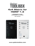
Audio/Video Scaler
Pro with Amplifier
EXT-AVSCALER-PRO
User Manual
www.gefen.com
f
ASKING FOR ASSISTANCE
Technical Support:
Telephone
Fax
(818) 772-9100
(800) 545-6900
(818) 772-9120
Technical Support Hours:
8:00 AM to 5:00 PM Monday thru Friday.
Write To:
Gefen Inc.
c/o Customer Service
20600 Nordhoff St
Chatsworth, CA 91311
www.gefen.com
[email protected]
Notice
Gefen Inc. reserves the right to make changes in the hardware, packaging and
any accompanying documentation without prior written notice.
Audio/Video Scaler Pro with Amplifier is a trademark of Gefen Inc.
© 2008 Gefen Inc., All Rights Reserved
All trademarks are the property of their respective companies
Rev X1
CONTENTS
1
Introduction
2
Operation Notes
3
Features
4
Unit Panel Layout
5
Unit Panel Descriptions
6
Unit Panel Descriptions
7
Connecting The Audio/Video Scaler Pro with Amplifier
8
RMT-SR-IR Remote Description
9
Operating The Audio/Video Scaler Pro with Amplifier
15 RMT-SR-IR Remote Installation
16 RMT-SR-IR Code Configuration
17 RS-232 Serial Control Interface
18 Rack Mount Installation
19 Specifications
20 Warranty
INTRODUCTION
Congratulations on your purchase of the Audio/Video Scaler Pro with Amplifier.
Your complete satisfaction is very important to us.
Gefen
Gefen delivers innovative, progressive computer and electronics add-on solutions
that harness integration, extension, distribution and conversion technologies.
Gefen’s reliable, plug-and-play products supplement cross-platform computer
systems, professional audio/video environments and HDTV systems of all sizes
with hard-working solutions that are easy to implement and simple to operate.
The Gefen Audio/Video Scaler Pro with Amplifier
The Gefen Audio/Video Scaler Pro is an all-in-one, commercial-grade, rackmountable AV switcher and scaler for a myriad of AV source types. Amplified
20W audio outputs for external speakers save further space by removing the
need for a separate amplifier. The Gefen Audio/Video Scaler Pro allows you to
scale video and digitally enhance key aspects such as color, aspect ratio, and AV
noise. External audio and video are digitized and combined into an HDMI output
signal along with external digital audio (S/PDIF and TOSLINK).
Video inputs can be standard definition or high definition television, computer
or High-Definition DVI-I (DVI-A or DVI-D), Component, Composite, S-Video,
and HDMI resolutions of up to 1080p. Outputs consist of two HDMI digital video
outputs, two digital audio outputs (S/PDIF, TOSLINK), and two 20W speaker
terminal outputs.
Anything from set-top boxes and DVD players to the next generation of gaming
consoles including the Xbox 360 and PS3 can be plugged into the Audio/Video
Scaler Pro.
Computer users will especially benefit with the scaling of VGA and DVI video to
make better use of their viewing areas on wide screen monitors or televisions.
How It Works
Audio/Video sources are connected to free ports on the scaler (see the next
paragraph for further details). Output devices such as HD displays connect to
one of the HDMI outputs. Easy to use on-screen menus accessible through
the IR remote control allow for effortless setup and image adjustment to
accommodate different viewing modes and screen sizes.
In order for HDMI output to contain digital audio, each video input source must be
paired with a like type of analog or digital audio in order for the scaler to output
HDMI with digital audio. For example, analog video sources VGA, Component
and Composite/S-Video are input along with analog 2-channel L/R audio. For
multichannel digital results, two HDMI or DVI-D sources could be input with
external digital audio (S/PDIF or TOSLINK). The result in both cases is a single
HDMI signal emerging from the two HDMI output jacks, with both embedded and
external digital audio available on the coaxial and optical outputs.
1
OPERATION NOTES
READ THESE NOTES BEFORE INSTALLING OR
OPERATING THE AUDIO/VIDEO SCALER PRO WITH AMPLIFIER
•
When initially powering on HDMI or DVI-D sources, it is important to have
the A/V Scaler Pro with Amplifier’s input selected to that source to ensure
that the EDID (display information) is relayed properly.
•
Only use speakers with an impedance of 8Ω with the A/V Scaler Pro with
Amplifier.
•
Discrete switching is available using the RS-232 serial communications port.
Please see page 17 for more information.
•
Only 2-channel stereo audio sources are output through the amplified
speaker terminals. Multi-channel audio will not be output through these
speaker outputs.
•
HDMI 1.2 compliant
•
HDCP compliant.
2
FEATURES
Features
•
Both digital and analog inputs are format converted and pixel re-scaled
through the Home Audio/Video Scaler Pro with Amplifier. It outputs a large
range of formats and resolutions that will easily match the native resolution/
format of your display to ensure highest picture quality.
•
DVI/HDCP/HDMI compliant input: Operates up to 165Mhz (Up to WUXGA
@60Hz)
•
Supports digital HD output up to 1080p
•
Integrated 8-bit triple-ADC/PLL.
•
Dual high quality scaling engines.
•
Dual 3-D motion adaptive de-interlacers with smooth low-angle edge.
•
Automatic 3:2 pull-down & 2:2 pull-down detection and recovery.
•
High performance frame rate conversion engine.
•
The Proprietary Advanced Color Engine technology gives: Brilliant and fresh
color, Intensified contrast and details, Vivid skin tone, Sharp edge, Accurate
and independent color control
•
Option to select audio input from HDMI or TOSLINK/SPDIF audio source
•
3D noise reduction on analog inputs only.
•
Operates through on-screen display (OSD) menu control and remote control
•
Digital Audio Delay to match audio/video timing
•
Less then one frame delay allowing for gaming
•
Aspect Ratio Control
•
Reset Button
Package Includes
(1) Gefen Audio Video Scaler Pro
(1) 6 Foot HDMI Cable (M-M)
(1) 24V DC Power Supply
(1) IR Remote control
(1) Set of Rack Ears
(1) User’s Manual
3
8
1
9
2
10
11
3
12
13
4
14
15
Back Panel
Front Panel
16 17
18
4
19
5
20
6
7
21
UNIT PANEL LAYOUT
UNIT PANEL DESCRIPTIONS
1
IR Receiver
This receivers will accept commands from the included RMT-SR-IR remote
control. There must be line-of-sight between this receiver and the remote control
for successful operation to occur.
2
Power Indicator LED
This LED indicator will become active once the included 5V DC power adapter
has bee properly connected between the sender unit and an open wall power
socket.
3
Selected Input LED
Each input source has an LED that will become active when it is selected. All
input sources are listed below.
CV
SV
Comp
HDMI 1
HDMI 2
DVI
Composite input
S-video input
Component input
HDMI 1 input
HDMI 2 input
DVI input
4
RS-232 Serial Communications Port
This port can accept commands from an RS-232 device to control the input
switching. Please see page 17 for more details on this feature.
5
Analog Stereo Input Port for Composite
This input will accept audio from one pair of RCA analog stereo cables for use
with the composite input.
6
Composite Input Port
This input will accept video from one RCA composite source. The composite
source will be digitally converted for output through the HDMI Output Port.
7
Analog Stereo Input Port for Component
This input will accept audio from one pair of RCA analog stereo cables for use
with the component input.
8
24V Power Supply Input Port
Connect the included 24V DC power supply to this input. Once properly
connected between the unit and an open wall power socket, the Power Indicator
LED should become active.
9
Stereo Speaker Terminals
The stereo speaker output terminals use spring-loaded compression. These
terminals are designed to accept 8Ω speakers.
5
UNIT PANEL DESCRIPTIONS
10 Reset Button
This button will reset the unit and cycle power off and on again.
11 Digital Audio Output Ports
There are two digital audio output types, S/PDIF (coaxial) and TOSLINK
(optical). Both digital outputs are always active.
12 HDMI Output Port
Connect the HDMI capable device to this output port. This output port supports
both audio and video.
13 Digital Audio Input Ports for HDMI 2
There are two digital audio input types, S/PDIF (coaxial) and TOSLINK (optical).
Both these inputs are individually selectable in the GUI for use with the HDMI 2
input.
14 HDMI 2 Input Port
Connect a HDMI source device to this input port. This input port supports both
audio and video.
15 Digital Audio Input Ports for HDMI 1
There are two digital audio input types, S/PDIF (coaxial) and TOSLINK (optical).
Both these inputs are individually selectable in the GUI for use with the HDMI 1
input.
16 HDMI 1 Input Port
Connect a HDMI source device to this input port. This input port supports both
audio and video.
17 Analog Stereo Input Port for DVI
This input will accept audio from one 3.5mm analog stereo cable for use with the
DVI input.
18 DVI-I Input Port
This input port will accept a DVI-A (analog) or DVI-D (digital) signal. DVI-A
signals will be digitally converted for output through the HDMI Output Port.
19 Analog Stereo Input Port for S-Video
This input will accept audio from one pair of RCA analog stereo cables for use
with the s-video input.
20 S-Video Input Port
This input will accept video from one s-video source. The s-video source will be
digitally converted for output through the HDMI Output Port.
21 Component Input Port
This input will accept video from one 3 RCA component source. The component
source will be digitally converted for output through the HDMI Output Port.
6
CONNECTING THE AUDIO/VIDEO SCALER PRO WITH AMPLIFIER
How to Connect the Audio/Video Scaler Pro with Amplifier
1.
Connect source devices to the Audio/Video Scaler Pro with Amplifier using
user supplied cables. The following input options are available.
Composite
- Single RCA video cable.
S-Video
- Single s-video cable.
Component - 3 RCA video cables.
HDMI 1
- Single HDMI cable.
HDMI 2
- Single HDMI cable.
DVI
- Single DVI-I, DVI-A, or DVI-D cable.
NOTE: All analog video sources will be converted to digital an output through the
HDMI Output Port.
2.
Connect audio sources to the Audio/Video Scaler Pro with Amplifier using
user supplied cables. Audio input options are available for the following
source inputs.
Composite
- Analog stereo using a 2 RCA analog stereo cable.
S-Video
- Analog stereo using a 2 RCA analog stereo cable.
Component - Analog stereo using a 2 RCA analog stereo cable.
HDMI 1
- Embedded audio through the HDMI cable and both a digital
S/PDIF (coaxial) and digital TOSLINK (optical) using digital
audio cables.
HDMI 2
- Embedded audio through the HDMI cable and both a digital
S/PDIF (coaxial) and digital TOSLINK (optical) using digital
audio cables.
DVI
- Analog stereo using a 3.5mm analog stereo cable.
NOTE: All analog sources will be converted to digital and output through the
HDMI, digital S/PDIF, and digital TOSLink outputs.
3.
Connect a HDMI cable device to the Audio/Video Scaler Pro with Amplifier’s
HDMI Output Port using the supplied HDMI cable.
4.
Connect a right and left speaker to the spring-loaded speaker terminals.
NOTE: Speaker impedance must be 8Ω or higher.
5.
Optionally, connect the digital S/PDIF (coaxial) or digital TOSLINK (optical)
audio outputs to a digital audio input device.
6.
Connect the included 24V DC power supply to the Audio/Video Scaler Pro
with Amplifier and to an open wall power socket.
7.
Power on the display first and the sources second.
7
RMT-SR-IR REMOTE DESCRIPTION
1
2
3
4
5
6
7
8
9
1.
Output - Cycles through
hrough the available output resolutions.
resolutions Please
Ple
see the section
A/V Scaler Pro with Amplifier CONFIGURATION / Output on page 8 for the
output resolution table.
2.
Input - Cycles though all of input sources. The selectable inputs are
Composite, S-Video, Component, HDMI 1, HDMI 2, and DVI.
3.
Power - Turns the unit on and off (standby).
4.
Exit - Exits the current menu option and menu system.
5.
Menu - Displays the menu system for adjustment of options.
6.
Navigation Keys - These include up, down, left, and right buttons for
navigating the menu system. (When not in the GUI, up and down will control
the up and down volume for the amplified speaker outputs.)
7.
The OK button will select specific menu options for adjustment and will also
confirm/cycle-through selections (Output/Input). (When not in the GUI, the
OK button will mute/un-mute all audio outputs)
8.
Reset - Resets the input and output resolutions to factory default.
9.
Auto Adjust - Sets the display for optimal resolution and aspect ratio based
on the display’s EDID information and the currently selected sources output
resolution.
8
OPERATING THE AUDIO/VIDEO SCALER PRO WITH AMPLIFIER
Entering the Menu System
Pressing the Menu button on the included RMT-SR-IR remote control will display the
GUI (graphical user interface) for adjustment options.
The GUI is overlaid onto the outgoing video to the display. Therefore, the selected
source must be outputting a compatible resolution for viewing on the display. If video
is not visible on the display, the GUI will also fail to be displayed. To correct this,
please follow the steps below.
1.
Verify that the source is on and outputting a video signal.
2.
Verify that the RMT-SR-IR remote channel is in the default position (page 13).
3.
Verify that the A/V Scaler Pro with Amplifier is selected to the chosen source.
4.
Press the Output button on the RMT-SR-IR remote control to cycle through
output resolutions until video is displayed. Please see page 8 for a listing of the
available output resolutions and cycle order.
Navigation
Use the directional buttons to navigate the menu system. Press the OK button to
enter a sub category and also to select a menu item for adjustment. Use the Left and
Right buttons to adjust the selected menu item. Press the EXIT or OK button to return
to the previous menu. Use the LEFT and RIGHT buttons to adjust selected options.
Pressing the EXIT button while in the main menu will exit out of the menu system.
MAIN MENU
The following are the main menu options. Use the UP and DOWN buttons to choose
your desired subcategory and press OK to enter it.
VIDEO
COLOR
OUTPUT
OSD
AUDIO
INFORMATION
VIDEO
Picture Mode
Preset and user configurable settings for different viewing scenarios. Preset settings
will not allow user adjustment. Only the USER option will allow customized video
settings. The USER settings are saved.
Options:
•
•
•
•
Standard - useful for general content
Movie - useful for dimly lit environments
Vivid - useful for accentuating colors for a more vibrant image
User - user configurable settings
NOTE: User settings are saved. However, user settings for the digital inputs (HDMI
1, 2 and DVI) are linked and user settings for the analog inputs (Composite, S-Video,
and Component) are linked. i.e. adjustments to video user settings made on HDMI 1
will be reflected in HDMI 2.
9
OPERATING THE AUDIO/VIDEO SCALER PRO WITH AMPLIFIER
VIDEO CONTINUED
Press OK to begin adjusting settings. Use the LEFT and RIGHT buttons to change
settings. Press the OK button once the desired settings are made.
Contrast
Adjusts the contrast in increments of 1 on a scale of 1 to 100 (default 50).
Brightness
Adjusts the brightness in increments of 1 on a scale of to 100 (default 50).
Hue
Adjusts the hue in increments of 1 on a scale of 1 to 100 (default 50).
Saturation
Adjusts the saturation in increments of 1 on a scale of 1 to 100 (default 50).
Sharpness
Adjusts the sharpness in increments of 1 on a scale of 1 to 100 (default 50).
Scale
Adjusts the aspect ratio of the video.
Options: Full, Overscan, Underscan, Letterbox Underscan, Pan Scan Underscan,
Letterbox Full, Pan Scan Full
4:3 Source
Example
16:9 Source
Example
Full - Stretches the image to fill the screen
Overscan - Stretches the image to fullscreen and just beyond the border of the display
Underscan - Stretches the image to fullscreen and just within the border of the screen
Letterbox Underscan - Stretches the image to 16:9 aspect ratio with underscan
Pan Scan Underscan - Stretches the image to 4:3 aspect ratio with underscan
Letterbox Full - Stretches the image to 16:9 aspect ratio without underscan
Pan Scan Full - Stretches the image to 4:3 aspect ratio without underscan
N.R. (Noise Reduction) - Only for Composite and S-Video Inputs
Reduces video noise inherent in analog video signals.
Options:
•
•
•
•
Off - default
Low
Middle
High
10
OPERATING THE AUDIO/VIDEO SCALER PRO WITH AMPLIFIER
VIDEO CONTINUED
H-Pos (Horizontal Position)
Adjusts the image’s horizontal position on the screen.
• Adjusts in increments of 1 on a scale of 1 to 100 (default is 50)
V-Pos (Vertical Position)
Adjusts the image’s vertical position on the screen.
• Adjusts in increments of 1 on a scale of 1 to 100 (default is 50)
Y/C Separation - Only for Composite Input
Selects the method in which the brightness and color are separated from the
composite video signal.
Options:
• Auto - automatically selects the optimal method (default)
• 2D - Separation based on single frame analysis
• 3D - Motion adaptive color separation based on multiple frame analysis
Coring - Only for Composite Input
Adjusts the threshold level for pixel noise evaluation. This relates to how much of the
image is processed in regards to noise reduction.
• Adjusts in increments of ~6.5 on a scale of 1 to 100. (default is 20)
OUTPUT
This menu sets the output resolution for all video sources. Use the directional buttons
to choose your desired output resolution and press the OK button to set it. These
outputs can be cycled through in the numbered order below when not in the menu
system by pressing the OUTPUT button on the RMT-SR-IR remote control.
1
2
3
4
5
VGA
SVGA
XGA
SXGA
UXGA
6
7
8
9
10
480i
480p
720p 60
1080i 60
1080p 60
11
12
13
14
15
576i
576p
720p 50
1080i 50
1080p 50
16
17
18
WXGA
WSXGA
WUXGA
Native
Native
This option will select the native resolution of the connected display based on the
EDID from the display.
NOTE: If a resolution that is not supported by the display is selected, the menu GUI
will not longer be visible. To correct this, press the OUTPUT button on the RMT-SRIR remote control and cycle through the output resolutions until a supported mode is
displayed.
11
OPERATING THE AUDIO/VIDEO SCALER PRO WITH AMPLIFIER
COLOR
Press OK to begin adjusting settings. Use the LEFT and RIGHT buttons to change
settings. Press the OK button once the desired settings are made.
Color Tone
Sets the color for the appearance of white. Only the USER option will allow
customized settings. The USER settings are saved.
•
•
•
•
Normal - Normal white color appearance (default)
Warm - Slight red shift to white appearance
Cool - Slight blue shift to white appearance
User - User adjustments to Red, Green, and Blue
Red
Adjust the red color in regards to the appearance of white for the USER setting.
• Adjustments are in increments of 1 from 1 to 100 (default is 50)
Green
Adjusts the green color in regards to the appearance of white for the USER setting.
• Adjustments are in increments of 1 from 1 to 100 (default is 50)
Blue
Adjusts the blue color in regards to the appearance of white for the USER setting.
• Adjustments are in increments of 1 from 1 to 100 (default is 50)
OSD (ON SCREEN DISPLAY)
Press OK to begin adjusting settings. Use the LEFT and RIGHT buttons to change
settings. Press the OK button once the desired settings are made.
H-Pos (Horizontal Position)
Adjusts the OSD’s horizontal position on the screen.
• Adjustments are in increments of 1 from 1 to 100 (default is 50)
V-Pos (Vertical Position)
Adjusts the OSD’s vertical position on the screen.
• Adjustments are in increments of 1 from 1 to 100 (default is 50)
Time Out
Adjusts the amount of idle time, in seconds, before the OSD is automatically exited.
• Adjustments are in increments of 1 from 1 to 100 (default is 10)
Background
Sets the transparency level of the OSD background.
• Adjustments are in increments of ~12.5 on a scale of 1 to 100 (default is 50)
12
OPERATING THE AUDIO/VIDEO SCALER PRO WITH AMPLIFIER
OSD (ON SCREEN DISPLAY) CONTINUED
Remote Channel
Sets the remote channel for use with the RMT-SR-IR remote control. If the selected
channel in this menu and does not match the channel set in the RMT-SR-IR remote,
the unit will cease to respond to IR commands from the remote.
• Selectable remote channel from 1 to 4 (default is 1)
AUDIO
Press OK to begin adjusting settings. Use the LEFT and RIGHT buttons to change
settings. Press the OK button once the desired settings are made.
Source
Sets the audio source for current input.
Options for Composite:
• L/R1 - Composite analog audio input (default)
Options for S-Video:
• L/R2 - S-Video analog audio input (default)
Options for Component:
• L/R3 - Component analog audio input (default)
Options for HDMI 1:
• HDMI1 - HDMI 1 internal audio (default)
• Optical1 - Optical input 1
• Coaxial1* - SPDIF input 1
Options for HDMI 2:
• HDMI2 - HDMI 2 internal audio (default)
• Optical2 - Optical input 2
• Coaxial2* - SPDIF input 2
Options for DVI:
• L/R4 - DVI analog audio input (default)
Delay
Sets the audio delay for lip syncing correction.
•
•
•
•
Off - No delay (default)
40ms - 40 millisecond audio offset
110ms - 110 millisecond audio offset
150ms - 150 millisecond audio offset
Sound
Select general audio output function. Mute/Un-mute can also be accessed by using
the OK button on the included RMT-SR-IR remote control when not in the GUI.
• On - Use selected audio source (default)
• Mute - No sound output
*Coaxial is also know as SPDIF
13
OPERATING THE AUDIO/VIDEO SCALER PRO WITH AMPLIFIER
AUDIO CONTINUED
Volume
Adjusts the amplified speaker output volume. The volume can also be accessed by
using the UP (volume up) and DOWN (volume down) buttons on the included RMTSR-IR remote control when not in the GUI.
• Adjusts in increments of 1 on a scale of 1 to 100 (default is 50)
INFORMATION
This menu will allow the user to view general information. There are no configurable
options in this menu.
•
•
•
•
Source - Displays current source
Input - Displays current input source resolution
Output - Displays current output resolution
Version - Displays current firmware revision
14
RMT-SR-IR REMOTE INSTALLATION
1.
Remove battery cover from the back of the RMT-SR-IR remote.
2.
Verify that dip switches 1 & 2 are in the down (OFF) position. (See page 13)
3.
Insert the battery, hold the battery so that you can see the positive side
facing up. The side that is not marked must be facing down.
4.
Test the RMT-SR-IR remote by pressing ONLY one button at a time. The
indicator light on the remote will flash once each time you press a button.
WARNING:
Do not press multiple buttons simultaneously and do NOT press buttons rapidly.
These actions will cause the remote to reset and steps 1-4 will have to be
repeated.
Note: The RMT-SR-IR ships with two batteries. Only one battery is required for
operation, the other battery is complimentary.
15
RMT-SR-IR CODE CONFIGURATION
How to Resolve IR Code Conflicts
In the event that IR commands from other remote controls conflict with the
supplied RMT-SR-IR remote control, changing the remote channel will alleviate
this issue. The RMT-SR-IR remote control has DIP SWITCHES for configuring
the remote channel. The A/V Scaler Pro with Amplifier must match the remote
channel set in the RMT-SR-IR remote control. Please see page 10 for instruction
on how to configure the channel on the A/V Scaler Pro with Amplifier. By default,
both the A/V Scaler Pro with Amplifier and the RMT-SR-IR remote control are set
to Channel 1.
Remote
Remote Channel 1:
Default
Remote Channel 2:
1
2
Remote Channel 3:
2
1
2
Remote Channel 4:
1
16
1
2
RS-232 SERIAL CONTROL INTERFACE
12345
12345
6789
6789
Only Pins 2 (RX), 3 (TX), and 5 (Ground) are used on the RS-232 serial interface
ASCII
1
2
5
6
g
Binary Table
Corresponding
Corresponds to
RMT16-IR
Binary
Input
Button
1
0011 0001
Input Cycle
2
0011 0010
Composite
5
0011 0101
Component
6
0011 0110
HDMI 1
16
0110 0111
HDMI 2
These commands can be used for discrete switching of the listed inputs. To
access the s-video input, use the ASCII command 2 followed by ASCII command
1 to switch to the composite input and then cycle to the s-video input. Likewise, to
access the DVI input, use the ASCII command G followed by ASCII command 1
to switch to the HDMI 2 input and then cycle to the DVI input. There are currently
no discrete commands available to immediately access the s-video and DVI
inputs.
RS232 Settings
Bits per second ................................................................................................. 19200
Data bits .................................................................................................................... 8
Parity .................................................................................................................. None
Stop bits .....................................................................................................................1
Flow Control ....................................................................................................... None
17
RACK MOUNT INSTALLATION
Rack mount ears are provided for installation of this unit into a 1U rack mount
space.
1.
2.
3.
4.
Locate the side screws on the unit.
Remove the front 2 screws that are located closest to the front of the unit.
Using the removed screws, screw the rack mounting bracket into the unit.
Repeat the procedure on the opposite side of the unit.
1
Front of unit
Rear of unit
2
3
4
18
SPECIFICATIONS
Digital Video Amplifier Bandwidth ............................................................ 165 MHz
Component Video Bandwidth ................................................................... 350 MHz
Input DDC Signal ......................................................................... 5 Volts p-p (TTL)
Input Video Signal .............................................................................. 1.2 Volts p-p
Maximum Resolution ............................................................... 1080p/1920 x 1200
Analog Video Connector (input) ............................. 1x VGA (via DVI-I Connector)
Analog Video Connector (input) .................................. 3x RCA Component Jacks
Analog Video Connector (input) .............................................. 1x RCA Composite
Analog Video Connector (input) ........................................................... 1x S-Video
Analog Audio Connector (input) ............................................. 1x 3.5mm Mini Jack
Digital Video Connector (input) ............................ 1x DVI-D (via DVI-I Connector)
Digital Video Connector (input) ............................................................... 1x HDMI
Digital Video Connector (output) ............................................................. 2x HDMI
Digital Audio Connector (output) ............................................ 1x Optical TOSLINK
Digital Audio Connector (output) ............................................... 1x Coaxial S/PDIF
Analog Audio Connector (output) ............................... 2x Pair L+R Spring-Loaded
Speaker Terminals (Amplified 20W RMS max.)
Power Supply/Power Consumption ................................... 24V DC/60 Watts max.
Dimensions ...................................................................... 17.2”W x 2.12”H x 6.8”D
Shipping Weight ............................................................................................ 6 lbs.
19