1
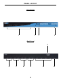
®
8x4 Matrix for
EXT-HDMI-844
User Manual
www.gefen.com
f
ASKING FOR ASSISTANCE
Technical Support:
Telephone
Fax
(818) 772-9100
(800) 545-6900
(818) 772-9120
Technical Support Hours:
8:00 AM to 5:00 PM Monday thru Friday Pacific Time
Write To:
Gefen Inc.
c/o Customer Service
20600 Nordhoff St
Chatsworth, CA 91311
www.gefen.com
[email protected]
Notice
Gefen Inc. reserves the right to make changes in the hardware, packaging and
any accompanying documentation without prior written notice.
8x4 Matrix for HDMI is a trademark of Gefen Inc.
© 2010 Gefen Inc., All Rights Reserved
All trademarks are the property of their respective owners
Rev A2
CONTENTS
1
Introduction
2
Operation Notes
3
Features
4
Panel Layout
5
Panel Descriptions
6
Connecting And Operating The 8X4 Matrix For HDMI
7
LED Array
8
RMT-16IR Remote Description
9
IR Code Configuration
10 EDID Management Feature
11 EDID Management Modes
12 RS-232 Serial Communications
13 RS-232 Serial Communications Commands
14 Specifications
15 Warranty
INTRODUCTION
Congratulations on your purchase of the 8x4 Matrix for HDMI. Your complete
satisfaction is very important to us.
Gefen
Gefen delivers innovative, progressive computer and electronics add-on solutions
that harness integration, extension, distribution and conversion technologies.
Gefen’s reliable, plug-and-play products supplement cross-platform computer
systems, professional audio/video environments and HDTV systems of all sizes
with hard-working solutions that are easy to implement and simple to operate.
The Gefen 8x4 Matrix for HDMI
The rack-mountable 8x4 Matrix for HDMI sends high definition video and
multichannel digital audio from any of 8 HDMI sources to any 4 Displays. The
HDMI inputs consist of 4 High Definition video switches that can each accept 2
video sources. This input scheme allows up to 8 sources to be available while
viewing any 4 on the output displays concurrently.
The 8x4 Matrix for HDMI eliminates the need to disconnect and reconnect
sources to displays. It works with Blu-Ray players, Set-Top boxes, Home
Theater PCs, and game consoles that connect to an HDMI display. Any source
is accessible at all times by any display by selecting it using an IR remote or an
RS-232 remote control device. The Matrix comes with rack ears for mounting in a
shelving system.
How It Works
Up to 8 HDMI sources (4 viewable at any one time) connect to the Matrix’s inputs
and up to four Displays connect to the Matrix’s outputs. Power up the 8x4 Matrix,
HDMI sources and all connected Displays. Select which HDMI sources you want
to view on each display using the IR remote. The result will be clear and vibrant
HDMI video with multichannel digital audio at each Display.
1
OPERATION NOTES
READ THESE NOTES BEFORE INSTALLING OR
OPERATING THE 8X4 MATRIX FOR HDMI
•
Important Note: The 8x4 Matrix for HDMI incorporates a 2x1 switch in front
of each input on a traditional 4x4 matrix. This allows for the connection of up
to 8 different HDMI source devices with a maximum of 4 sources available
for viewable at any one time. Each of the 4 switched inputs on the 8x4 Matrix
for HDMI are labeled as “A” and “B”. Both “A” and “B” for each input cannot
be active at the same time.
Example A (Multiple outputs viewing the same input source)
Devices: 1A (DVD player) & 1B (Cable STB)
Scenario: Outputs 1 and 2 are both viewing input 1A (DVD).
Action: User viewing output 1 switches the input from 1A (DVD) to 1B
(STB).
Result: Both outputs 1 and 2 will be switched to viewing 1B (STB).
Example B (Multiple outputs viewing separate input sources)
Devices: 1A (DVD player), 1B (Cable STB), and 2A (Video Game system)
Scenario: Output 1 is viewing 1A and output 2 is viewing 2A.
Action: User viewing output 1 switches the input from 1A (DVD) to 1B
(STB).
Result: Output 2 is not affected by the change of 1A to 1B because it is
viewing a source (2A) on a different input.
•
Display information (EDID) from the displays attached to the 8x4 Matrix for
HDMI need to be sent back to the input sources. Please see page 10 for
EDID management features and options.
•
HDMI 1.2 compliant (HDMI 1.3 compatible)
•
HDCP compliant
2
FEATURES
Features
•
Switches any eight HDMI™ sources to 4 Displays
•
Distributes any of the four switched inputs (total of eight inputs) to any
combination of the four HDMI™ output displays
•
Maintains high resolution video - beautiful, sharp HDTV resolutions up to
1080p, 2k, and computer resolutions up to 1920 x 1200 are easily achieved
•
Serial RS-232 remote port for switching via control automation
•
HDMI™ 1.2 Compliant (HDMI 1.3 Compatible); HDCP Compliant
•
Discrete IR remote (included)
•
Rack ears included
Package Includes
(1) 8x4 HDMI Matrix
(1) RMT-16IR Remote Control
(8) 6-Foot HDMI Cable (M-M)
(1) 24V DC Power Supply
(1) User’s Manual
(1) Rack Ears (set)
3
PANEL LAYOUT
Front Panel
1
2
3
4
Back Panel
5
6
7
8
9
4
10
11
PANEL DESCRIPTIONS
1
Selected Input LED Indicator
Each of the 4 outputs has an 4 LED array to indicate which source is currently
selected on the 8x4 Matrix for HDMI. Each of the inputs can accept up to 2
sources (A and B) and the LED array will behave in 2 modes to indicate which
of the two sources for input is selected. Please see the operation section for a
complete description on how the LED array functions.
2
IR (Infrared) Receiver
This receiver will accept command for switching between input HDMI devices
using the included RMT-16IR remote control. Line of sight must be preserved for
proper operation.
3
IR (Infrared) Receiver Extension
An optional IR Receiver Extension (part # EXT-RMT-EXTIR) can be connected if
the unit is placed in a location that will not provide line of sight to the included IR
remote control. The IR extension can then be placed in a location where it can
receive commands form the IR remote control.
4
Power LED Indicator
This LED will become active once the included 24V DC power supply is properly
connected between the unit and an open wall power socket.
5
RS-232 Serial Communications Port
This port is used to control multiple functions available on the 8x4 Matrix for
HDMI. Please see page 12 for complete details on the serial communication
features that are used on this product.
6
HDMI 1 Inputs
There are two inputs, labeled 1A and 1B, that will accept an HDMI source
device. Only one of these inputs can be active at any given time.
7
HDMI 2 Inputs
There are two inputs, labeled 2A and 2B, that will accept an HDMI source
device. Only one of these inputs can be active at any given time.
8
HDMI 3 Inputs
There are two inputs, labeled 3A and 3B, that will accept an HDMI source
device. Only one of these inputs can be active at any given time.
9
HDMI 4 Inputs
There are two inputs, labeled 4A and 4B, that will accept an HDMI source
device. Only one of these inputs can be active at any given time.
10 HDMI Outputs 1 to 4
Connect up to 4 HDMI capable devices (i.e. display) to these output ports.
11 24V DC Power Receptacle
Connect the included 24V DC power supply between this input and an open
wall power socket.
5
CONNECTING AND OPERATING THE 8X4 MATRIX FOR HDMI
How to Connect the 8x4 Matrix for HDMI
1.
Connect up to 8 HDMI source devices to the 8x4 Matrix for HDMI using the
included HDMI cables.
NOTE: Please be aware that each input has two available HDMI ports and that
only one will be active at any given time. It is recommended that commonly used
HDMI sources be put on separate inputs (i.e. 1A and 2A, not 1A and 1B) so that
these devices are always available.
2.
Connect up to 4 HDMI capable devices (i.e. displays) to the 8x4 Matrix for
HDMI using user supplied HDMI cables.
3.
Connect the included 24V DC power supply between the power input on the
unit and an open wall power socket.
4.
Power on all output devices first and the source devices second.
How to Operate the 8x4 Matrix for HDMI
The 8x4 Matrix for HDMI can be controlled by either the included RMT16-IR
remote control or the RS-232 serial communications port.
For RMT-16IR remote control functions please see page 8.
For RS-232 serial communication functions please see page 12.
6
LED ARRAY
The LED array on the 8x4 Matrix for HDMI is designed to inform the user of the
current source to output routes. Each output has a 4 LED array that will indicate
which source is currently selected. Each input can accept two sources and
therefore the LED array will act differently according to which input, “A” or “B”, is
active for each.
•
An input’s “A” source will be indicated by an single LED (the selected “A”
input) that is ON.
•
An input’s “B” source will be indicated by the reverse; a single LED will be
OFF (the selected “B” input) while the remaining 3 LEDs will be ON.
The examples below will show some scenarios to illustrate the LED array
functionality. Please note that it is not possible to have both “A” and “B” inputs
active at the same time for any given input.
= LED ON
= LED OFF
Scenario 1 (”A” Example)
Output-1
Output 1 is selected to 1A
Output-2
Output 2 is selected to 2A
Output-3
Output-4
Output 3 is selected to 3A
Output 4 is selected to 4A
Scenario 2 (”B” Example)
Output-1
Output 1 is selected to 1B
Output-2
Output 2 is selected to 2B
Output-3
Output-4
Output 3 is selected to 3B
Output 4 is selected to 4B
Scenario 3 (Mixed Example)
Output-1
Output 1 is selected to 3A
Output-2
Output 2 is selected to 4B
7
Output-3
Output-4
Output 3 is selected to 2A
Output 4 is selected to 1A
RMT-16IR REMOTE DESCRIPTION
The RMT-16IR remote control will allow the user to select which source will be routed
to which output. Each of the 4 outputs are assigned a group of 4 buttons that will
correspond to the 4 source inputs. Each button on the RMT-16IR remote control will
toggle between the “A” and “B” sources for each input. Please use the information
below when selecting the desired source for each display.
RMT-16IR Button
Source
Display
1
Toggle 1A and 1B
1
2
Toggle 2A and 2B
1
3
Toggle 3A and 3B
1
4
Toggle 4A and 4B
1
5
Toggle 1A and 1B
2
6
Toggle 2A and 2B
2
7
Toggle 3A and 3B
2
8
Toggle 4A and 4B
2
9
Toggle 1A and 1B
3
10
Toggle 2A and 2B
3
11
Toggle 3A and 3B
3
12
Toggle 4A and 4B
3
13
Toggle 1A and 1B
4
14
Toggle 2A and 2B
4
15
Toggle 3A and 3B
4
16
Toggle 4A and 4B
4
8
IR CODE CONFIGURATION
Why would I need to change the remote channel?
In some instances, the 8x4 Matrix for HDMI may use IR codes that conflict with other
IR remote control devices. The unit may switch inputs when another brand IR remote
control is used or the RMT-16IR may cause other brand IR controlled devices to
behave unexpectedly.
I am experiencing the issues listed above. What do I do?
In these cases it is recommended to change the IR channel that the RMT-16IR
remote control and the 8x4 Matrix for HDMI use. The IR channel is configured
independently on the RMT-16IR remote control and the 8x4 Matrix for HDMI but the
channel selection must match on both units for proper operation.
How Do I change the Remote Channel?
There are service DIP switches on the RMT-16IR remote control and also inside the
8x4 Matrix for HDMI. Use the diagrams below to locate and change the IR channel to
one that is not the default. Remember that the channel must match on both the unit
and remote control for successful operation.
RMT-16IR Remote Control
Remove the battery cover on the rear side of the RMT-16IR remote control
to expose the DIP switches.
2 DIP switch bank for IR channel configuration.
Remote Channel 1:
Default
Remote Channel 2:
1
2
Remote Channel 3:
1
2
1
2
Remote Channel 4:
1
2
8x4 Matrix for HDMI
The IR channel DIP switches for the 8x4 Matrix for HDMI are located on an 8 bank DIP switch inside of
the unit and on its main-board. To open the unit, remove all screws on the underside and side of the unit.
Remove all HEX screws on the rear panel. This includes the screws above each HDMI port and on each
side of the RS-232 serial communications port. Carefully slide the unit apart. Locate DIP switches 3 and
4. Once adjustments are complete replace all screws and.
Remote Channel 1:
Default
Remote Channel 2:
1 2 3 4 5 6 7 8
1 2 3 4 5 6 7 8
Remote Channel 3:
Remote Channel 4:
1 2 3 4 5 6 7 8
1 2 3 4 5 6 7 8
9
EDID MANAGEMENT FEATURE
EDID. What is it and what is it used for?
Under normal circumstances, a source device (digital and analog) will require
information about a connected device/display to assess what resolutions
and features are available. The source can then cater its output to send
only resolutions and features that are compatible with the attached device/
display. This information is called EDID (Extended Display Information Data)
and a source device can only accept and read one EDID from a connected
device/display. Likewise, the source an only output one resolution for use by a
connected device/display.
Why is EDID so important with the 8x4 Matrix for HDMI?
The 8x4 Matrix is complex piece of technology that replicates and switches
between multiple inputs and outputs. Each connected source device will require
one EDID to read. EDID management is carefully handled by 8x4 Matrix for
HDMI to provide a single EDID for each source to read.
What options do I have to manage the EDID in the 8x4 Matrix for HDMI?
First, it is important to note that each source device can only output one video/
audio signal type. This includes resolutions and timings. When multiple devices/
displays are used, such as with the 8x4 Matrix for HDMI, it is important to use
devices/displays that have similar or compatible resolutions/features. This will
ensure that the single video/audio signal produced by the source device is
accepted by all of the connected output devices/displays.
The user has the option, through a combination of DIP switch settings within
the 8x4 Matrix for HDMI, to choose how the unit will manage the EDID from
multiple HDMI devices/displays. Therefore the user has some control over
the resolutions/features that the source devices will output. The 8x4 Matrix for
HDMI has a multiple EDID management modes that will control how the EDID
information from multiple devices/displays are combined, ignored, and routed.
How do I change EDID modes in the 8x4 Matrix for HDMI?
There is an bank of 8 DIP switches located on the main-baord inside of the 8x4
Matrix for HDMI. DIP switches 1, 2, 5, and 7 are used in different combinations to
manage the EDID modes.
TIP: EDID modes and IR code channels can also be managed via the RS-232
serial communications port. For this to work, all DIP switches must be in the OFF
position. This is the factory default setting. If you wish to use this feature, please
do not open the unit. See page 12 for more information on the RS-232 serial
communication features.
To access these DIP switches it will be required to open the unit. To do this,
remove all screws on the underside and side of the unit. Remove all HEX screws
on the rear panel. This includes the screws above each HDMI port and on each
side of the RS-232 serial communications port. Carefully slide the unit apart.
10
EDID MANAGEMENT MODES
v. 3019
EDID Modes
The diagram below illustrates the 8 DIP switch bank.
1
2
3
4
5
6
7
8
DIP SWITCH
Function
1
EDID Mode
2
EDID Mode
3
IR Channel
4
IR Channel
5
EDID Mode
6
N/A
7
EDID Mode
8
N/A
Use DIP switches 1, 2, 5, and 7 to select the desired EDID management mode.
EDID Mode 0 (Switch 1=OFF Switch2=OFF Switch5=ON)
•
EDID is copied from the device connected to the first active hdmi output port.
•
All features newer that HDMI 1.2 are cleared.
EDID Mode 1 (Switch 1=ON Switch2=OFF Switch5=ON)
•
Same as Mode 0 and adds basic audio support.
EDID Mode 2 (Switch 1=OFF Switch2=ON Switch5=ON)
•
Same as Mode 0 and adds full audio support.
EDID Mode 3 (Switch 1=ON Switch2=ON Switch5=OFF)
•
EDID is generated based on the common video and audio features of all of
the connected output devices.
EDID Mode 4 (Switch 1=OFF Switch2=ON Switch5=OFF)
•
Same as Mode 3 and adds basic audio support.
EDID Mode 5 (Switch 1=ON Switch2=OFF Switch5=OFF)
•
Same as Mode 3 and adds full audio support.
EDID Mode 6 (Switch 1=OFF Switch2=OFF Switch5=OFF) DEFAULT
•
EDID is generated based on the common video features of all of the
connected devices and the combined audio features of all of the connected
output devices.
EDID Mode 7 (Switch 1=ON Switch2=ON Switch5=ON)
•
EDID is passed unmodified from the device connected to the first active
output port.
EDID Mode 8 (Switch 1=OFF Switch2=OFF Switch5=OFF Switch7=ON)
•
Preloaded generic 1080p EDID is used.
EDID Mode A (Switch 1=OFF Switch2=ON Switch5=OFF Switch7=ON)
•
Same as mode 6 but will record and store the EDID in memory. This EDID will
persist no matter what displays are disconnected or reconnected thereafter.
EDID will remain even upon power cycle. A user submitted EDID can be
uploaded in this mode using a Gefen HDMI Signal Generator.
11
RS-232 SERIAL COMMUNICATIONS
What features are available via the RS-232 serial communications port?
The 8x4 Matrix for HDMI can accept commands through the RS-232 serial
communications port located on the rear panel. The current RS-232 control
features are:
•
Switching/routing of inputs to outputs without the RMT-16IR remote control.
•
Switch EDID management modes without opening the unit to physically
modify DIP switches.
•
Change IR code channel without opening the unit to physically modify DIP
switches. (The IR code channel will still need to be manually modified on the
RMT-16IR remote control to match the code channel.)
How do I use these features?
These features were initially intended for utilization by custom installers in
automated setups. However, these features can be tested by using any Windows
PC with the Hyperterminal program.
What pins are used for communication with the 8x4 Matrix for HDMI?
Only pins 2 (Receive), 3 (Transmit), and 5 (Ground) are used for communication.
A null-modem adapter should not be used with this product.
12345
12345
6789
6789
Only Pins 2 (RX), 3 (TX), and 5 (Ground) are used on the RS-232 serial interface
What are the communication port settings?
Bits per second ................................................................................................. 19200
Data bits .................................................................................................................... 8
Parity .................................................................................................................. None
Stop bits .....................................................................................................................1
Flow Control ....................................................................................................... None
12
RS-232 SERIAL COMMUNICATIONS COMMANDS
Switching/Routing Binary Table
ASCII
Command
A1/a1
A2/a2
A3/a3
A4/a4
A5/a5
A6/a6
A7/a7
A8/a8
B1/b1
B2/b2
B3/b3
B4/b4
B5/b5
B6/b6
B7/b7
B8/b8
Input
Output
1A
1B
2A
2B
3A
3B
4A
4B
1A
1B
2A
2B
3A
3B
4A
4B
1
1
1
1
1
1
1
1
2
2
2
2
2
2
2
2
ASCII
Command
C1/c1
C2/c2
C3/c3
C4/c4
C5/c5
C6/c6
C7/c7
C8/c8
D1/d1
D2/d2
D3/d3
D4/d4
D5/d5
D6/d6
D7/d7
D8/d8
Input
Output
1A
1B
2A
2B
3A
3B
4A
4B
1A
1B
2A
2B
3A
3B
4A
4B
3
3
3
3
3
3
3
3
4
4
4
4
4
4
4
4
EDID Management Modes
Use the ASCII commands below to change the EDID modes. For a description of
each mode please see page10.
ASCII
EDID Mode
ASCII
EDID Mode
m0
0
m5
5
m1
1
m6
6
m2
2
m7
7
m3
3
m8
8
m4
4
mA
A
IR Remote Channel Configuration
All DIP switches inside the unit must be in their default OFF position. Use the ASCII
commands below to change the IR code channel. Please ensure that the IR remote
channel on the RMT-16IR matches any channel that is set by these commands. For
a description of the IR code channel configuration please see page 9.
ASCII
Remote Channel
r1
1
r2
2
r3
3
r4
4
13
SPECIFICATIONS
Video Amplifier Bandwidth ....................................................................... 165 MHz
Input Video Signal .............................................................................. 1.2 Volts p-p
Input DDC Signal ......................................................................... 5 Volts p-p (TTL)
Single Link Range ................................................................... 1080p/1920 x 1200
HDMI Connector ................................................................. Type A 19 Pin Female
Remote Control Port .......................................... RS-232 Female, 3.5mm Mini-Stereo
Power Supply ............................................................................................ 24V DC
Power Consumption ....................................................................... 60 Watts (max)
Dimensions .................................................................. 17.1”W x 1.7”H x 6.5”D
Shipping Weight .......................................................................................... 9 lbs.
14
WARRANTY
Gefen warrants the equipment it manufactures to be free from defects in material
and workmanship.
If equipment fails because of such defects and Gefen is notified within two (2)
years from the date of shipment, Gefen will, at its option, repair or replace the
equipment, provided that the equipment has not been subjected to mechanical,
electrical, or other abuse or modifications. Equipment that fails under conditions
other than those covered will be repaired at the current price of parts and labor in
effect at the time of repair. Such repairs are warranted for ninety (90) days from
the day of reshipment to the Buyer.
This warranty is in lieu of all other warranties expressed or implied, including
without limitation, any implied warranty or merchantability or fitness for any
particular purpose, all of which are expressly disclaimed.
1.
Proof of sale may be required in order to claim warranty.
2.
Customers outside the US are responsible for shipping charges to and from
Gefen.
3.
Copper cables are limited to a 30 day warranty and cables must be in their
original condition.
The information in this manual has been carefully checked and is believed to
be accurate. However, Gefen assumes no responsibility for any inaccuracies
that may be contained in this manual. In no event will Gefen be liable for
direct, indirect, special, incidental, or consequential damages resulting from
any defect or omission in this manual, even if advised of the possibility of such
damages. The technical information contained herein regarding the features and
specifications is subject to change without notice.
For the latest warranty coverage information, please visit Gefen’s Warranty web
page at http://www.gefen.com/kvm/aboutus/warranty.jsp
PRODUCT REGISTRATION
Please register your product online by visiting Gefen’s web site at
http://www.gefen.com/kvm/Registry/Registration.jsp
15
Rev A2
20600 Nordhoff St., Chatsworth CA 91311
1-800-545-6900
818-772-9100
www.gefen.com
fax: 818-772-9120
[email protected]