1
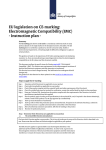
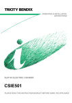
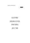
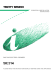
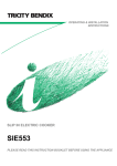
GE Monogram® Installation Instructions 36" Gas Cooktops Models ZGU3650 Before you begin—Read these instructions completely and carefully. IMPORTANT: Save these instructions for local inspector’s use. IMPORTANT: OBSERVE ALL GOVERNING CODES AND ORDINANCES. NOTE TO INSTALLER: Be sure to leave these instructions with the Consumer. NOTE TO CONSUMER: Keep these instructions with your Owners Manual for future reference. WARNING This appliance must be properly grounded. See “Power Supply”, page 5. CAUTION CAUTION ATTENTION Cet appareil doit être correctement mis à la terre. Voir << Alimentation électrique >> à la page 5. If you have a question concerning the installation of this product, call the GE Answer Center® Consumer Information Service at 800.626.2000, 24 hours a day, 7 days a week. If you received a damaged cooktop, you should immediately contact your dealer or builder. Proper installation is the responsibility of the installer. Product failure due to improper installation is not covered under the GE Appliance Warranty. See the Owners Manual for warranty information. For Monogram local service in your area, 1-800-444-1845. For Monogram service in Canada, 1-888-880-3030. For Monogram Parts and Accessories, call 1-800-626-2002. FOR YOUR SAFETY If you smell gas: 1. Open windows. 2. Don’t touch electrical switches. 3. Extinguish any open flame. 4. Immediately call your gas supplier. FOR YOUR SAFETY Do not store or use combustible materials, gasoline or other flammable vapors and liquids in the vicinity of this or any other appliance. • Installation of this cooktop must conform with local codes, or in the absence of local codes, with the National Fuel Gas Code, ANSI Z223.1, latest edition. In Canada, installation must conform with the current Contents Design Information Models Available ............................................... 3 Advance Planning ............................................ 3 Dimensions and Clearances ............................ 3 Installation Preparation Tools and Materials Required ......................... 4 Cut the Opening .............................................. 4 Power Supply Locations ................................... 5 2 Natural Gas Installation Code, CAN/CGAB149.1 or the current Propane Installation Code, CAN/CGA-B149.2, and with local codes where applicable. • This cooktop has been design-certified by the American Gas Association according to ANSI Z21.1, latest edition and Canadian Gas Association according to CAN/CGA-1.1 latest edition. • Your cooktop must be electrically grounded in accordance with local codes or, in the absence of local codes, in accordance with the National Electrical Code (ANSI/NFPA 70, latest edition). In Canada, electrical grounding must be in accordance with the current CSA C22.1 Canadian Electrical Code Part 1 and/or local codes. Installation Install Cooktop ................................................. 6 Install Pressure Regulator ................................ 7 Connect Electrical ............................................ 7 Assemble Burners, Check Ignition ................. 7 Design Information G a s Updraf t Cooktop ZGU3650 36" gas updraft cooktops For those who prefer gas heat for cooking, the Monogram built-in gas updraft cooktop offers the cooking method of choice. These cooktops are only 3" deep and can be installed over cabinet drawers. Dimensions and clearances These models are shipped for natural gas operation. They can be converted to liquid propane. (Order JXLP56 conversion kit). 4-5/8" Min. to Vertical Combustible Surface 36" 19-3/4" 18-1/8" 34-1/2" 3" 8-13/16" Min. to Wall 2-1/4" Min. 13" Max. 36" Min. 3-7/8" Min. to Vertical Combustible Surface When Installed 30" Min. 18" Min. 8" Min. to Wall When Installed Both Sides 1-1/2" Min. to Front of Countertop When Installed Advance planning • Refer to “Installation Preparation” for information on appropriate placement and necessary clearances when planning installation. • Avoid placing cabinetry directly above cooktop when possible. • If cabinetry is used above cooking surface: –Use cabinets no more than 13" deep. –Maintain 30" minimum clearance between cooktop and unprotected cabinets directly above cooktop. –If clearance is less than 30", protect cabinet bottoms with flame-retardant millboard at least 1/4" thick, or gysum board at least 3/16" thick, covered with 28 gauge sheet steel or .02" thick copper. –Clearance between cooktop and protected cabinetry must not be less than 24". –An exhaust hood that projects at least 5" beyond front of cabinets can reduce risk of burns caused by reaching over heated surface units. –Working areas adjacent to the cooktop should have 18" minimum clearance between countertop and cabinet bottom. • Use the Monogram gas updraft cooktop with any 36" or wider exhaust hood, if desired; no special ventilation is required. • Installation must conform with local codes. In the absence of local codes, the gas cooktop must comply with the National Fuel Gas Code, ANSI Z223.1, latest edition. 3 Installation Preparation G a s Updraf t Cooktop Tools and Materials Required • Self-adhesive gasket (supplied) • Two clamping brackets and screws (supplied) • Gas pressure regulator (supplied) • Large flat-blade screwdriver • Saw • Carpenter’s square • Pipe wrench • Manual gas line shut-off valve • 3/4" NPT x 3/4" I.D. or 1/2" NPT x 1/2" I.D. flare union adaptor for connection to supply line • 1/2" NPT x 3/4" I.D. or 1/2" I.D. flare union adaptor for connection to regulator • Gas-resistant pipe joint sealant • 5 foot AGA-certified flexible metal appliance connector, 3/4" or 1/2" I.D. to match gas supply line: –If required by local codes, use solid pipe with fittings. Note: Purchase new flexible line, DO NOT USE OLD, PREVIOUSLY USED FLEXIBLE LINE. Cut the Opening 8-13/16" Min. Cutout To Side Wall 8-13/16" Min. to Side Wall 4-5/8" Min. Cutout to Vertical Combustible Surface 18-1/8" 34-1/2" 2-1/4" Min. From Front of Countertop Caution: Wallcoverings, countertops and cabinets should withstand 200°F heat generated by the cooktop. Measure carefully when cutting countertop. Make sure sides of opening are parallel and rear and front cuts are exactly perpendicular to sides. • The Monogram gas updraft cooktop is designed to fit in a 36" or larger base cabinet. • The countertop cutout for cooktop must be: –34-1/2" wide –18-1/8" deep –Allow at least 4-5/8" clearance between back of cutout and wall. –Allow at least 8-13/16" clearance from right and left side of cutout to adjacent wall. –Allow at least 2-1/4" clearance between front of cutout and front edge of countertop. 4 • Cooktop requires 3" free space below countertop. • If installing cooktop above a cabinet with drawers, it may be necessary to use a shorter length drawer to allow clearance for gas connection. • In some cases, two 3/8" I.D. 45° elbows and a pipe nipple may be added between regulator and cooktop to move regulator further back in order to avoid interference with drawer. Installation Preparation G a s Updraf t Cooktop Power supply locations Gas supply: These cooktops are designed to operate on natural gas at 4" of water column pressure or on LP gas at 10" of water column pressure. –These cooktops are shipped from the factory set for natural gas. If you decide to use this cooktop with LP gas, conversion adjustments must be made by a service technician or other qualified person. JXLP56 conversion kit is required for LP operation. • The pressure regulator must be connected in series with the manifold of the cooktop and must remain in series with the supply line regardless of type of gas being used. For proper operation, the maximum inlet pressure to the regulator must be no more than 10" water column pressure for natural gas and 14" water column pressure for LP gas. • When checking the regulator, the inlet pressure must be at least 1" greater than the regulator output setting. –If the regulator is set for 4" of water column pressure, the inlet pressure must be at least 5". –If the regulator is set for 10" of water column pressure, the inlet pressure must be at least 11". For ease of installation, and if local codes permit, the gas supply line into the cooktop should be 1/2" or 3/4" ID flexible metal appliance connector, three to five feet long. Note: Purchase new flexible line. DO NOT USE OLD, PREVIOUSLY USED FLEXIBLE LINE. • Make gas connection through rear wall, or on cabinet floor at rear, as illustrated. 2" Min. Below Bottom of Counter 1-5/8" From Right of Cutout 5/8" Forward of Back of Cutout Electrical supply: This cooktop features pilotless electric ignition for energy savings and reliability. It operates on a 120 volt, 60 Hz power supply. A separate circuit, protected by a 15 amp time delay fuse or circuit breaker, is required. • A properly-grounded 3-prong receptacle should be located within reach of cooktop’s four foot power cord. IMPORTANT: (Please read carefully). FOR PERSONAL SAFETY, THIS APPLIANCE MUST BE PROPERLY GROUNDED. The power cord of this appliance is equipped with a three-prong (grounding) plug which mates with a standard three-prong grounding wall receptacle to minimize the possibility of electric shock hazard from this appliance. The customer should have the wall receptacle and circuit checked by a qualified electrician to make sure the receptacle is properly grounded and has correct polarity. Where a standard two-prong wall receptacle is encountered, it is the personal responsibility and obligation of the customer to have it replaced with a properly grounded threeprong wall receptacle. Do Not, Under Any Circumstances, Cut Or Remove The Third (ground) Prong From The Power Cord. Do not use an extension cord. 5 Installation G a s Updraf t Cooktop 1 Step Install Cooktop Note: If the cooktop is installed into a 36" base cabinet, the pressure regulator MUST BE installed to the bottom of the cooktop before the cooktop is placed into the cabinet. Countertop • Remove packaging from the cooktop. • To insure a good fit, position the cooktop over the cutout opening and carefully lower into place. Check edges all the way around to be sure all cutout edges are concealed and there are no gaps. • Carefully, lift and remove the cooktop. 1/16" 3/8" • Cut a 3/16" gasket strip in half. Peel off the backing and apply to the underside of the glass cooktop edge. –on each side at least 3/8" from the back and as close to the edge as possible without protruding. • Apply the other gasket strip to the underside of the glass at the front of the cooktop. • Remove remaining adhesive backing. • Position the cooktop over the opening, making sure that the power cord is dropped into the cabinet. • Lower the cooktop into the cutout, pressing gently and evenly to seat. 6 Gasket Note: If the cooktop is installed in a 36" base cabinet, the mounting brackets cannot be used because of interference with the cabinet sides. In this case, the cooktop can be secured to the cabinet with angle brackets (not supplied). –Remove one screw at the bottom of the cooktop body on both sides and secure the bracket with those screws. Then, secure the brackets to the cabinet sides. • Insert hold-down bracket into highest slots on the right and left sides of the cooktop: –Cooktop has three slots, the highest available will depend on the thickness of the countertop. • Secure the brackets to the underside of the countertop with screws provided. Installation Gas Updraft Cooktop 2 Step Install Pressure Regulator • Install the supplied pressure regulator and nipple in the gas line as close to the cooktop inlet as possible. Allowances for ventilation ducting may be necessary. –Make sure the regulator is installed in the right direction. • Install a manual shut-off valve in the gas line in an easily accessible location. Note: Instead of using solid piping to connect to pressure regulator, an approved flexible metal appliance connector may be used between the pipe stub and the shut-off valve and the pressure regulator, if local codes permit. – Appropriate flare nuts and adapters are required at each end of the flexible connector. • Turn on the gas. Check for leaks using a liquid leak detector at all joints in the system (the pressure test nipple is adjacent to the gas inlet pipe on the rear right hand side of the cooktop bottom. CAUTION Do not use a flame to check for gas leaks. PRUDENCE IL NE FAUT PAS UTILISER CAUTION Regulator Solid Piping or Flexible Connector Shut-Off Valve Pipe Stub IMPORTANT: Disconnect the cooktop and the individual shut-off valve from the gas supply piping system during any pressure testing of that system at test pressures greater than 1/2 psig. Isolate the cooktop from the gas supply piping system by closing the individual manual shut-off valve to the cooktop during any pressure testing of the gas supply piping system at test pressures equal to or less than 1/2 psig. DE FLAMME POUR VÉRIFIER S’IL Y A DES FUITES. 3 4 Step • Plug power cord into properly grounded receptacle. Connect electrical Step • Assemble burner as shown. Check to be sure that burner heads are securely seated and caps are positioned as shown. Medium Head And Cap Medium Head And Cap Small Head And Cap Burner Grate Assemble burners, check ignition Medium Head And Cap Large Head And Cap • Check for proper ignition: –Push in one control knob and turn 90° to HIGH position. Burner Head –The igniter will spark and the burner will light; the igniter will cease sparking when Burner Bowl the burner is lit. –First test may require some time, while air is flushed out of the gas line. Electrode –Turn knob to OFF. –Repeat the procedure for each burner. 7 Burner Cap Make sure slot in burner head is positioned over electrode Front NOTE: While performing installations described in this book, safety glasses or goggles should be worn. To obtain specific information concerning any Monogram product or service, call GE Answer Center® consumer information service at 800.626.2000—any time, day or night. For Monogram local service in your area, call 1-800-444-1845. ® Monogram. General Electric Company Louisville, KY 40225 NOTE: Product improvement is a continuing endeavor at General Electric. Therefore, materials, appearance and specifications are subject to change without notice. Pub. No. 49-80000-1 Part No. 183D5580P074 2000 GE Appliances (N.D. 505) 5/00 Printed in Mexico