1
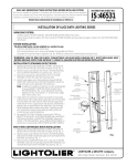
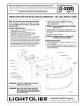
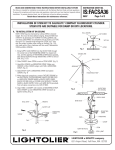
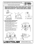
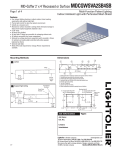
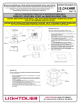
IS:4511 Instructions for Installation of Arco Oval Series Fixtures. Page 1 of 2 0995 Read and understand these instructions before installing fixture. This fixture is intended for installation in accordance with the National Electrical Code and local or Federal code specifications. To prevent electric shock, turn off electricity at fuse box before proceeding. Retain these instructions for maintenance reference. NOTE: This instruction sheet covers both compact fluorescent and incandescent fixtures. Although illustration shows compact fluorescent, the incandescent version assembles and installs in the same manner. NOTE: The Backplate is provided with (4) Auxiliary Mounting Knockout holes for direct mounting to wall surfaces. These can be used for added security or where direct Outlet Box mounting is not available. To remove plug in Knockout holes, follow steps 1 through 3 below. This Backplate can be mounted horizontally of vertically. See Fig 1 below for proper orientation for type of Lens Assembly and desired position. 1. Position blunt ended punch or awl in center of Knockout hole and firmly hit with hammer to punch plug through. Repeat for remaining Knockouts (Fig. 1). Caution: Always wear eye protection (safety goggles) when removing Auxiliary Mounting Knock-Outs. 2. Position Backplate in desired position over Outlet Box and mark location of (4) Auxiliary Holes on wall surface. 3. Determine the appropriate mounting hardware required for type of wall material fixture is being mounted to (i.e. toggle bolts or molly screws for plaster or gysum board walls, wood screws, etc.) 4. Thread Crossbar Mounting Screws into Crossbar as shown in Fig. 1. 5. Using appropriate slots in Crossbar, secure Crossbar to Outlet Box using Outlet Box Screws (provided with Outlet Box). 6. While supporting Backplate make connections: black fixture lead or fixture without tracer marks to hot (black) supply lead; white fixture lead or fixture lead with tracer markers to neutral (white) supply lead. Un-insulated wire is a ground wire and must be connected to grounding terminals or ground lead inside Outlet Box. Use Wire Nuts (local hardware item). Push connections back into Outlet Box. Position this edge of Backplate up for horizontal mounting of these Lens Assemblies. Outlet Box Wire Nut Ground Wire Crossbar Crossbar Mounting Screws UP R FO SE THE L Position this edge of Backplate up for vertical mounting of this Lens Assembly ES EN S Outlet Box Screws THI S LENS Auxiliary Mounting Knock-out Battery Nut AUX. Mounting Hole T MOUN AUX. Backplate OUNT Gasket Safety Cable Loop Mounting Screw FIG.1 Lens Assembly LIGHTOLIER a GENLYTE company. 631 Airport Road, Fall River, MA 02720 (508) 679-8131 FAX (508) 647-4710 © 1995 IS:4511 0995 Instructions for Installation of Arco Oval Series Fixtures. Page 2 of 2 7. Position Backplate over Crossbar allowing Crossbar Mounting Screws to come through Holes in Backplate. Secure Backplate in position by installing (2) Battery Nuts over Crossbar Mounting Screws and tighten. 8. If using Auxiliary Mounting Knockout, install the appropriate hardware determined in step 3. 9. Position Screw through Loop in Safety Cable and thread Screw into Mounting Boss on inside of Lens Assembly (Fig. 2). 10. Install recommended lamp(s). 11. Position Lens Assembly over Backplate making certain the Safety Cable does not interfere with the Gasket (fig. 1). 12. Secure Lens Assembly in place by tightening the (2) Mounting Screws on the face of Lens Assembly. CAUTION: Maximum wattage as marked on fixture must not be exceeded. WARNING--(Risk of Fire) most dwellings built before 1985 have supply wire rated for 60° C. Consult a qualified electrician before installing. CAUTION: For wet locations, in accordance with Underwriters Laboratories requirements, a line of caulking compound such as acrylic latex or silicone must be placed around the perimeter of Backplate to seal water away from the outlet box and back openings. Glass Mounting Boss Lens Assembly Loop Mounting Screw Safty Cable FIG. 2 Inside Lens Assembly LIGHTOLIER a GENLYTE company. 631 Airport Road, Fall River, MA 02720 (508) 679-8131 FAX (508) 647-4710 © 1995