1
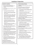
Installation
Instructions
If you have questions, call 800-GE-CARES or visit our website at: www.monogram.com
36" Stainless Steel
Gas Cooktops
Natural Gas Model:
ZGU375NS
LP Gas Model
ZGU375LS
Monogram.
®
Before you begin—Read these instructions completely and carefully.
IMPORTANT: Save these instructions for local inspector’s use.
IMPORTANT: OBSERVE ALL GOVERNING CODES AND ORDINANCES.
NOTE TO INSTALLER: Be sure to leave these instructions with the Consumer.
NOTE TO CONSUMER: Keep these instructions with your Owners Manual
for future reference.
WARNING
This appliance must be properly grounded and with correct polarity.
See “Power Supply”, page 6.
ATTENTION
Cet appareil doit être correctement mis à la terre. Voir << Alimentation
électrique >> à la page 6.
Proper installation is the responsibility of the
installer. Product failure due to improper
installation is not covered under the GE
Appliance Warranty. See the Owners Manual
for warranty information.
For Monogram local service in your area, call
1.800.444.1845.
For Monogram service in Canada, call
1.888.880.3030.
For Monogram Parts and Accessories, call
1.800.626.2002.
In the Commonwealth of Massachusetts:
• This product must be installed by a licensed plumber or gas fitter.
• When using ball type gas shut off valves, they shall be T-handle type.
• A flexible gas connector, when used, must not exceed 3 feet.
FOR YOUR SAFETY
If you smell gas:
1. Open windows.
2. Don’t touch electrical switches.
3. Extinguish any open flame.
4. Immediately call your gas supplier.
FOR YOUR SAFETY
Do not store or use combustible materials,
gasoline or other flammable vapors and
liquids in the vicinity of this or any other
appliance.
• Installation of this cooktop must conform
with local codes, or in the absence of local
codes, with the National Fuel Gas Code,
ANSI Z223.1, latest edition. In Canada,
installation must conform with the current
Contents
Design Information
Models Available ......................................................... 3
Dimensions and Clearances ..................................... 3
Advance Planning ....................................................... 3
Advance Planning, Installation Options .................. 4
Tools and Materials Required ................................... 4
Installation Preparation
Cut the Opening ........................................................... 5
Power Supply Locations ............................................ 6
2
Natural Gas Installation Code, CAN/CGAB149.1 or the current Propane Installation
Code, CAN/CGA-B149.2, and with local
codes where applicable.
• This cooktop has been design-certified by
the American Gas Association according to
ANSI Z21.1, latest edition and Canadian Gas
Association according to CAN/CGA-1.1
latest edition.
• Your cooktop must be electrically grounded
in accordance with local codes or, in the
absence of local codes, in accordance with
the National Electrical Code (ANSI/NFPA
70, latest edition). In Canada, electrical
grounding must be in accordance with the
current CSA C22.1 Canadian Electrical Code
Part 1 and/or local codes.
Installation
Install Cooktop ............................................................. 7
Install Pressure Regulator ......................................... 7
Connect Electrical ....................................................... 8
Assemble Burners, Check Ignition .......................... 8
Installation Option
Installation with Downdraft Vent ............................. 9
Installation with Warming Drawer ......................... 10
Installation with Single Oven .................................. 11
Design Information
Stainless Steel G a s Cooktop
ZGU375NS
36" natural gas cooktop
ZGU375LS
36" LP gas cooktop
For those who prefer gas heat for
cooking, the Monogram built-in
gas stainless steel cooktop offers
the cooking method of choice.
These models are factory set for either natural gas or
LP gas operation. Be sure to order the correct model
for the installation situation.
Dimensions
and clearances
13"
Max.
36-1/2"
20-5/8"
Deep
at Center
19-3/4"
* 2-15/16" Min.
From Cooktop
to Vertical
Combustible
Surface When
Installed
5-1/2"
30"
36" Min. 18" Min. Min.
3-3/8" Min. From Cutout
to Vertical Combustibles
18-7/8"
35-5/16"
11-9/16" Min. to
Wall From Cutout
2-3/4" Min.
11" Min. to Wall
From Cooktop Edge
When Installed Both Sides
* If a countertop backsplash is used, it must be constructed
of non-combustible materials (such as masonry, ceramic,
granite, stainless steel, etc.) whenever the cutout to rear
vertical surface is less than 3-3/8".
IMPORTANT: Always maintain 2-3/4" Min. clearance from
cutout to front edge of countertop.
Advance
planning
• Refer to “Installation Preparation” for
information on appropriate placement
and necessary clearances when planning
installation.
• Avoid placing cabinetry directly above
cooktop when possible.
• If cabinetry is used above cooking surface:
–Use cabinets no more than 13" deep.
–Maintain 30" minimum clearance between
cooktop and unprotected cabinets directly
above cooktop.
–If clearance is less than 30", protect cabinet
bottoms with flame-retardant millboard at
least 1/4" thick, or gysum board at least
3/16" thick, covered with 28 gauge sheet
steel or .02" thick copper.
–Clearance between cooktop and protected
cabinetry must not be less than 24".
–An exhaust hood that projects at least 5"
beyond front of cabinets can reduce risk of
burns caused by reaching over heated
surface units.
–Working areas adjacent to the cooktop
should have 18" minimum clearance
between countertop and cabinet bottom.
• Use the Monogram gas stainless steel cooktop with any 36" or wider exhaust hood with
350 CFM or greater air flow rating.
• Installation must conform with local codes.
In the absence of local codes, the gas cooktop must comply with the National Fuel Gas
Code, ANSI Z223.1, latest edition.
3
Design Information
Stainless Steel G a s Cooktop
Advance
planning
installation
options
Tools and
Materials
Required
4
Cooktop and ZVB36 Downdraft Vent
Combination Installation. See page 9.
These cooktops may be installed with a 36"
Monogram Downdraft Vent, models ZVB36.
See page 9 for cutout and clearances.
–The countertop must have a deep flat
surface to accommodate the combined
installation of the cooktop and vent.
–The downdraft vent with blower, motor and
ductwork will occupy the base cabinet.
–Consideration must be given to electrical
and gas supply locations. See page 6.
–Read the Downdraft Vent Installation
Instructions packed with the product, or
to review ahead of time, order Pub. No.
49-80185.
Cooktop and ZTD910 Warming Drawer
Combination Installation. See page 10.
These cooktops may be installed over a
Monogram 30" Warming Drawer, models
ZTD910. See page 10 for cutout and clearances.
–Consideration must be given to electrical and
gas supply locations. See page 6.
–Read the Warming Drawer Installation
Instructions packed with the product, or
to review ahead of time, order Pub. No.
49-8937.
• Gas pressure
regulator (supplied)
• 90° street elbow
(supplied), may be
required with a
downdraft vent
combination
installation.
• Wok ring (accessory
supplied on some
models)
• 1/2" NPT x 3/4"
I.D. or 1/2" I.D.
flare union adaptor
for connection to
regulator
• Gas-resistant pipe
joint sealant
• Saw
• Carpenter’s square
• Pipe wrench
• Manual gas line
shut-off valve
• 3/4" NPT x 3/4"
I.D. or 1/2" NPT x
1/2" I.D. flare
union adaptor for
connection to
supply line
Cooktop and ZET837 Single Oven
Combination Installation. See page 11.
These cooktops may be installed over a
Monogram 30" Oven, model ZET1038.
See page 11 for cutout and clearances.
–Consideration must be given to electrical and
gas supply locations. See page 6.
–Read the 30" Oven Installation Instructions
packed with the product, or to review ahead
of time, order Pub. No. 49-80188.
• 5 foot AGA-certified
flexible metal
appliance
connector, 3/4" or
1/2" I.D. to match
gas supply line:
–If required by local
codes, use solid
pipe with fittings.
NOTE: Purchase
new flexible line,
DO NOT USE OLD,
PREVIOUSLY USED
FLEXIBLE LINE.
Installation Preparation
Stainless Steel G a s Cooktop
Cut the
Opening
11-9/16"
Min.
Cutout
To Side
Wall
11-9/16" Min.
to Side Wall
3-3/8" Min.
to Rear Vertical
Combustibles
18-7/8"
35-5/16"
2-3/4"
Min. From
Front of
Countertop
CAUTION: Wallcoverings,
countertops and cabinets should
withstand 200°F heat generated
by the cooktop.
Measure carefully when cutting countertop.
Make sure sides of opening are parallel and
rear and front cuts are exactly perpendicular
to sides.
• The Monogram stainless steel gas cooktop is
designed to fit in a 42" or larger base
cabinet. If the cooktop is installed into a 36"
cabinet base, modifications may be required.
A 36" cabinet base must allow for installation
of hold-down clips at the sides. The side
walls may need to be cut away to provide
this space.
• The countertop cutout for cooktop must be:
–35-5/16" min. to 35-7/16" max. wide
–18-7/8" min. to 19" max. deep
–Allow at least 3-3/8" clearance between
back of cutout and vertical combustible
wall.
–Allow at least 11-9/16" clearance from right
and left side of cutout to adjacent wall.
–Allow at least 2-3/4" clearance between
front of cutout and front edge of
countertop.
NOTE: Cutout
dimensions have a
tolerance of plus or
minus 1/8"
42" Wide
Cabinet Base
Recommended
• The cooktop chassis occupies 5-1/2" space
below countertop.
• If installing cooktop above a cabinet with
drawers, it may be necessary to use a shorter
length drawer to allow clearance for gas
connection.
• In some cases, two 3/8" I.D. 45° elbows and a
pipe nipple may be added between regulator
and cooktop to move regulator further back
in order to avoid interference with drawer.
NOTE: Some countertops made from solid surface materials,
such as Corian® may require special cutout preparation (such
as radius corners and aluminum foil tape). Always consult the
countertop manufacturer for specific instructions.
Optional Combination Installations.
This cooktop may be installed in combination
with a ZVB36 Monogram Downdraft Vent, with
a ZTD910 Warming Drawer, or a ZET1038
single wall oven. See “Optional Installations”,
pages 9 through 11, for cutout and clearances
of these installations.
5
Installation Preparation
Stainless Steel G a s Cooktop
Power supply
locations
Gas supply:
These cooktops are shipped from the factory
set for either natural gas or LP gas. Check to
be sure you have the correct cooktop for the
type of gas being used.
• The pressure regulator must be connected
in series with the manifold of the cooktop
and must remain in series with the supply
line regardless of type of gas being used.
• The natural gas model is designed to
operate at 5" water column pressure.
A regulator is required at the natural gas
source to provide a maximum of 7" water
pressure to the cooktop regulator.
• The liquid propane model is designed to
operate at 10" water column pressure.
A regulator is required at the LP source
to provide a maximum of 14" water pressure
to the cooktop regulator.
For ease of installation, and if local codes
permit, the gas supply line into the cooktop
should be 1/2" or 3/4" ID flexible metal
appliance connector, three to five feet long.
NOTE: Purchase new flexible line. DO NOT
USE OLD, PREVIOUSLY USED FLEXIBLE
LINE.
• Make gas connection through rear wall, or
on cabinet floor at rear, as illustrated.
Electrical supply:
This cooktop features pilotless electric
ignition for energy savings and reliability.
It operates on a 120 volt, 60 Hz power supply.
A separate circuit, protected by a 15 amp time
delay fuse or circuit breaker, is required.
Optional Combination Installations
This cooktop may be installed in combination with a ZVB36 Monogram Downdraft
Vent, a ZET1038 Single Oven or a ZTD910
Warming Drawer.
• The gas and electrical supply must be
located where it will not interfere with
vent housing, the oven or the warming
drawer. See pages 9 through 11 for
alternate installation requirements.
6
16"
7"
8"
42"
NOTE: Locate gas and electrical
supply within shaded area. Locations
shown for a 42" cabinet base, adjust
when using other cabinet size.
• A properly-grounded 3-prong receptacle
should be located within reach of cooktop’s
four foot power cord.
IMPORTANT: (Please read carefully). FOR
PERSONAL SAFETY, THIS APPLIANCE
MUST BE PROPERLY GROUNDED.
• The power cord of this appliance is
equipped with a three-prong (grounding)
plug which mates with a standard threeprong grounding wall receptacle to minimize the possibility of electric shock hazard
from this appliance.
• The customer should have the wall receptacle and circuit checked by a qualified
electrician to make sure the receptacle is
properly grounded and has correct polarity.
• Where a standard two-prong wall receptacle
is encountered, it is the personal responsibility and obligation of the customer to have it
replaced with a properly grounded threeprong wall receptacle.
Do Not, Under Any Circumstances, Cut Or
Remove The Third (ground) Prong From The
Power Cord.
Do not use an extension cord.
IMPORTANT: Improper grounding and
improper polarity of the house wiring can
cause continuous sparking of the ignition
system. Be sure to check for correct
grounding and polarity.
Installation
Stainless Steel G a s Cooktop
1
Step
Install
Cooktop
2
Step
Install
Pressure
Regulator
• Remove packaging from the cooktop.
• Position the cooktop over the opening,
making sure that the power cord is dropped
into the cabinet.
• Lower the cooktop into the cutout, pressing
gently and evenly to seat.
• Thumbscrew brackets are located on the
right and left sides of the cooktop.
• Turn thumbscrews to touch the underside of
the countertop until just finger tight. Do not
overtighten.
Countertop
1" Min.
NOTE: Countertop
must be a minimum
of 1" thick at the
thumbscrew locations.
Thumbscrew
To Cooktop
• Install the supplied pressure regulator and
nipple in the gas line as close to the cooktop
inlet as possible.
–Make sure the regulator is installed in the
right direction. See arrow on underside of
regulator.
• Install a manual shut-off valve in the gas line
in an easily accessible location.
NOTE: Instead of using solid piping to
connect to pressure regulator, an approved
flexible metal appliance connector may be
used between the pipe stub and the shut-off
valve to the pressure regulator, if local codes
permit.
– Appropriate flare nuts and adapters are
required at each end of the flexible
connector.
• Turn on the gas. Check for leaks using a
liquid leak detector at all joints in the system
(the pressure test fitting is on the side of the
regulator).
CAUTION Do not use a flame to check for
gas leaks.
Cooktop
Regulator
NOTE: Refer to flow
direction arrow on
underside of regulator.
Solid Piping
or Flexible
Connector
Shut-Off
Valve
Pipe Stub From
House Gas Supply
IMPORTANT: Disconnect the cooktop and
the individual shut-off valve from the gas
supply piping system during any pressure
testing of that system at test pressures greater
than 1/2 psig. Isolate the cooktop from the
gas supply piping system by closing the
individual manual shut-off valve to the
cooktop during any pressure testing of the
gas supply piping system at test pressures
equal to or less than 1/2 psig.
PRUDENCE IL NE FAUT PAS UTILISER
CAUTION
DE FLAMME POUR VÉRIFIER S’IL Y A
DES FUITES.
7
Installation
Stainless Steel G a s Cooktop
3
• Check to be sure the receptacle is properly
wired by checking for proper polarity and
grounding.
• Plug in power cord.
4
• Remove tape on burners.
• Assemble burner as shown. Check to be sure
that burner heads and caps are securely
seated. Pin(s) must completely engage holes
to ensure proper assembly.
Step
Connect
electrical
Step
Assemble
burners,
check ignition
• Check for proper ignition:
–Push in one control knob and turn 90° to
HIGH position.
–The igniter will spark and the burner will
light; the igniter will cease sparking when
the burner is lit.
–First test may require some time, while air is
flushed out of the gas line.
–Turn knob to OFF.
–Repeat the procedure for each burner.
IMPORTANT: If the ignitor electrodes
continue to spark after the burners are lit,
check that each burner component is
assembled and seated properly by observing
constant gaps between each layer. Disassemble
and reassemble as required.
To aid reassembly, each
brass Burner Head is
marked with a clock face.
Replace the Burner Head
with the arrow pointing
to the rear of the cooktop
(12 o’clock position).
8
Installation Options
Installation With
Downdraft Vent
Stainless Steel G a s Cooktop
Cooktop Installation with a 36" Monogram
Downdraft Vent, models ZVB36.
The installation of the downdraft vent with
this cooktop requires careful consideration.
Both the cooktop and the vent must be
installed according to each specific installation instruction. For accurate planning,
review the Downdraft Vent Installation
Instructions in advance, order Pub. No.
49-80185.
Countertop Requirements:
The countertop must have a deep flat surface
to accommodate the cooktop and vent.
Countertops with a rolled front edge and
backsplash will not provide the flat surface
area required.
• Review the illustration to determine the
countertop surface requirements.
–All cutout clearances for this installation
must be observed.
Top View–Countertop Surface
9/16"
36-1/2"
34" Vent Cutout
9/16"
1/8" Gap
2-9/16"
21-7/16"
Cutout
Depth
18-7/8"
Cooktop
Cutout
Depth
1/4" Overlap
35-5/16"
Cooktop Area Cutout
3-3/8" Min.
Cooktop
Cutout to
Rear Vertical
Combustible
Surface
22-3/4"
Total Flat
Surface
Required
at Center
7/16" Cooktop Overlap
(1-1/4" at Center)
Front Edge of Countertop
2-3/4" Min. Clearance to Cutout
Base Cabinet Requirements:
The combined installation will fit in a standard 24" deep base cabinet. A base cabinet at
least 42" wide is recommended.
–The vent housing, blower and ductwork will
occupy the base cabinet.
11-9/16" Min. Cutout
to Wall, Both Sides
Power Supply:
If local codes permit, the vent and cooktop
may operate from the same 120V, 15 amp
duplex outlet. Locate the gas and electrical
supply as shown on page 6.
Ductwork:
Ductwork should be planned in advance.
• The blower system is designed for use with
3-1/4" x 10" ductwork. It can be transitioned
to 6" round.
–The ductwork MUST be vented to the
outside.
–The duct run should not exceed 150 ft. or
equivalent length when bends or various
fittings are used.
Again, refer to Downdraft Vent Installation
Instructions for details.
9
Installation Options
Installation With
Warming Drawer
Stainless Steel G a s Cooktop
Cooktop Installation Over a 30" Monogram
Warming Drawer, models ZTD910.
These cooktops may be installed over a 30"
Warming Drawer. Both the cooktop and the
warming drawer must be installed according
to each specific installation instruction. For
accurate planning, review the Warming
Drawer Installation Instructions in advance,
order Pub. No. 49-8937.
–Allow 2" clearance between the cooktop
bottom and the top of the cutout, or 7-1/2"
from the top of the countertop as illustrated.
Power Supply:
If local codes permit, the cooktop and warming drawer may operate from the same 120V
duplex outlet. See page 6.
1-1/2" Cabinet Top
Install 2x4 or 2x2 Anti-Tip Block
Against Rear Cabinet Wall 9" From
Cutout Floor to Bottom of Block
Cooktop 35-5/16"
25"
18-7/8"
2-3/4" Min.
7-1/2" Min.
9"
28-1/2"
9-1/4"
36"
Countertop
Height
23-1/2" Min.
NOTE: When installing a Monogram Warming Drawer below
a cooktop, a solid barrier must be installed at least 1" from
the lowest point of the bottom of cooktop burner box to the
top of cutout. See Warming Drawer Installation Instructions
for details.
IMPORTANT: Base Cabinet Requirements
for Combined Installation
A 42" wide base cabinet should be used.
Narrow custom doors or decorative stiles can
be used to fill the 6" gap on each side of the
warming drawer.
• 30" or 36" base cabinets are not
recommended.
9"
Install
2x4 or 2x2
Anti-Tip Block
Against Rear
Cabinet Wall
9" From Floor
to Bottom
of Block
2x4 or 2x2
Runners or Solid
Bottom, 25" on Center
NOTE: The support must be level, rigidly
mounted and capable of supporting 150 lbs.
10
Installation Options
Installation With
Single Oven
Stainless Steel G a s Cooktop
Cooktop Installation Over a 30" Monogram
Single Oven, models ZET1038.
These cooktops may be installed over the
Monogram ZET1038 single oven. Both the
cooktop and the oven must be installed
according to each specific installation instruction. For accurate planning, review the 30"
Oven Installation Instructions in advance,
order Pub. No. 49-80188.
–Allow 6" Min. clearance from the top of the
countertop to the top of the oven cutout.
Power Supply:
The oven requires a separate, properly
grounded 30 Amp, 3-wire 120/208 or
120/240 volt, 60 Hz power supply. The cooktop requires a separate 120V power supply.
See page 6. Where codes permit, the gas shutoff valve may be located in an adjacent cabinet
or other easily accessible location.
1-1/2" Cabinet Top
25"
Cooktop 35-5/16"
18-7/8"
2-3/4" Min.
6" Min.
28" Min.
28-3/8" Max.
36"
Countertop
Height
23" Max.
23-1/2" Min.
25"
Use two 2x4's or equivalent runners spaced 25" centerline
to centerline in the opening & flush with top of toekick.Or,
elevate the oven floor to desired height.The support must
be level, rigidly mounted and capable of supporting 200lbs.
IMPORTANT: Base Cabinet Requirements
for Combined Installation
A 42" wide base cabinet should be used.
Narrow custom doors or decorative stiles can
be used to fill the 6" gap on each side of the
oven.
• For best appearance the cooktop should be
centered over the oven.
• 30" or 36" base cabinets are not
recommended.
11
NOTE: While performing installations described in this book,
safety glasses or goggles should be worn.
For Monogram® local service in your area, call
1-800-444-1845.
NOTE: Product improvement is a continuing endeavor
at General Electric. Therefore, materials, appearance
and specifications are subject to change without notice.
Pub. No. 49-80218-1
Dwg. No. 164D4290P370
03-04 JR
11173-E