1
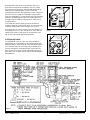
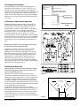
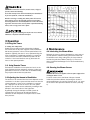
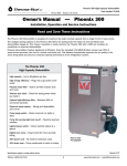
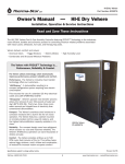
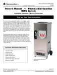
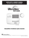
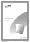
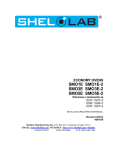
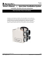
Quiet-Vent
TS-174E
Owner’s Manual — Quiet-Vent Ventilation System
Installation, Operation & Service Instructions
Read and Save These Instructions
Quiet-Vent is a central exhaust ventilation system that replaces noisy, low output and
unreliable bath fans. With today’s tight homes, Quiet-Vent presents one of the best ways
to eliminate pollutants (i.e. normal household chemicals, outgasing from construction
materials, furniture and carpeting) by exhausting them out of the home. Quiet-Vent
also reduces humidity levels that otherwise lead to mildew in closets, condensation on
windows, insulation and walls which, over just a few years can cause costly damage.
Specifications subject to change without notice.
Toll-Free 1-800-533-7533
11/06
www.thermastor.com • [email protected]
1 Specifications
Table of Contents
1 Specifications.........................................................1
2 Installation.............................................................1
2.1 Back-Drafting Open Combustion Devices............2
2.2 Location of the Quiet-Vent.................................2
2.3 Fresh Air Inlets.................................................3
2.4 Hanging the Quiet-Vent.....................................4
2.5 Ducting to and from the Quiet-Vent....................4
2.6 Wiring the Quiet-Vent........................................4
3 Operation..............................................................5
3.1 Using the Timers..............................................5
3.2 Adjusting the Amount of Ventilation...................5
4 Maintenance..........................................................5
4.1 Lubricating the Blower Motor.............................5
4.2 Cleaning the Blower Screen..............................5
5 Service..................................................................6
5.1 Circuit Breaker Trips.........................................6
5.2 Blower Operates on One Speed Only..................6
5.3 7-Day Timer Does Not Advance..........................6
5.4 Fan Motor........................................................6
5.5 Warranty..........................................................6
6 Service Parts List...................................................6
7. Warranty................................................................7
Model: Quiet-Vent
Electrical Specs: 110-120Vac, 60Hz, 1ph
Max HACR Type Circuit Breaker or Fuse: 10A
Blower: Fasco 7090-1806 0.65 Amps, Thermally Protected
Capacitor: 370 VAC, 6 MFD
2 Installation
WARNING: To reduce the risk of fire, electric shock, or injury to
persons, observe the following:
A. Installation work and electrical wiring must be done by
qualified person(s) in accordance with all applicable
codes and standards, including fire-rated construction.
B. Sufficient air is needed for proper combustion and
exhausting of gases through the flue (chimney) of fuel
burning equipment to prevent backdrafting. Follow the
heating equipment manufacturer’s guideline and safety
standards such as those published by the National
Fire Protection Association (NFPA), and the American
Society for Heating, Refrigeration and Air Conditioning
Engineers (ASHRAE), and the local code authorities.
C. When cutting or drilling into wall or ceiling, do not
damage electrical wiring and other hidden utilities.
D. Ducted fans must always be vented to the outdoors.
E. If this unit is to be installed over a tub or shower, it
must be marked as appropriate for the application.
F. NEVER place a switch where it can be reached from a
tub or shower.
Serial No.____________________________________
Purchase Date________________________________
Dealer’s Name _______________________________
2.1 Back-Drafting Open Combustion Devices
Read the operation and maintenance instructions
carefully before using this unit. Proper adherence to
these instructions is essential to obtain maximum
benefit from your Quiet-Vent Ventilation system.
CAUTION: Do not use open combustion heating appliances (unless
equipped with power exhaust) in a home equipped with exhaust
fans (i.e., bath fans, kitchen hoods, down draft stoves, or the QuietVent System).
Under certain conditions, these fans may cause the backdrafting
of toxic combustion by-products that are hazardous to human
health and could cause death. Therefore, we strongly recommend
using only closedcombustion (direct-vent or aerodynamically
decoupled) heating appliances in weather tight homes. Most furnaces, fireplaces and water heaters are now available with sealed
combustion or power exhaust.
2.2 Location of the Quiet-Vent
Ideally each bathroom and the kitchen are ducted with a
4” duct to the Quiet-Vent (See Fig. 3). To make installation
easy, the Quiet-Vent has one 6” and three 4” duct inlet
Connections (see Fig. 2). The 6” outlet of the Quiet-Vent is
ducted to the outside of the home. The Quiet-Vent should
Toll-Free 1-800-533-7533
www.thermastor.com • [email protected]
be positioned in the home to minimize the amount of
duct and wire required for installation. The unit should
be mounted and oriented to allow periodic blower oiling,
cleaning of the internal blower screen via the side
mounted clean-out port, and adjustment of the 7-day timer
(the timer can be remote mounted away from the QuietVent (see paragraph F). In cold climates the unit should be
located in a heated space to prevent condensation from
forming inside the cabinet. A basement or utility room is
an ideal location.
If the Quiet-Vent and its ducting must be located in a
unheated space in a cold climate, they must be insulated
to prevent condensation from forming in the system.
If the Quiet-Vent is used to correct a moisture problem in
14.5” near the
an existing house, a 6” duct should be run from
ceiling in the center of the house to the Quiet-Vent
(see
11” Hanger Strap
(4 supplied)
Fig. 3). This will provide adequate ventilation.
2.3 Fresh Air Inlets
14.5”
11” Hanger Strap
(4 supplied)
11” Hanger Strap
(4 supplied)
Oil Port
6”
Inlet
13.125”
Electrical
Box Cover
6”
Inlet
13.5”
7-Day Timer
4”
Inlet
Figure 1
11” Hanger Strap
(4 supplied)
Oil Port
6”
Electrical
The “FRESH 80” fresh air 13.125”
inlets areInlet
recommended
to
Box Cover
provide fresh air to the bedrooms and prevent excessive
depressurization. These fresh air inlets should be located
on an exterior wall near the ceiling in any isolated rooms
13.5”
that are occupied for extended periods of time with the
door closed. These vents have an adjustable
opening, a
7-Day Timer
filter and a shut off valve. One air inlet is recommended in
each bedroom.
6”
Inlet
4”
Inlet
4”
Inlet
4”
Inlet
Figure 2
Figure 3
Toll-Free 1-800-533-7533
4”
Inlet
www.thermastor.com • [email protected]
4”
Inlet
2.4 Hanging the Quiet-Vent
Circuit to next timer in bath or kitchen
The Quiet-Vent has four vibration absorbing straps for
hanging from joists, rafters, or trusses (See Fig. 1 & 3)
and use (4) 1/4” diameter lag bolts or the equivalent.
Locate the unit to minimize the ducting from the baths and
kitchen to the Quiet-Vent inlets and from the Quiet-Vent
outlet to the outside. Because the oiling system depends
on gravity, the unit must be oriented with the hanger bolts
on the top.
Timer switch
ground
Timer switch ground
115 Volt circuit/ground from
Quite-Vent to bath or kitchen
10-15 AMP 115 Volt
circuit with ground from
main electrical service
2.5 Ducting to and from the Quiet-Vent
Alternative Electrical
Layouts
All flexible ducting connected to the unit should be UL
listed. The preferred method of ducting the exhaust air
from the rooms is to use 4” round duct from 4” x 6”
register heads located in the wall cavities or the ceiling.
For routing through 3.5” stud cavities, flatten the 4”
round duct to 3.25”. If a 4” duct length from a full bath
or kitchen exceeds 50’, two 4” ducts or a 6” duct is
recommended. The 4” duct can be either metal or flexible
and can be routed to the Quiet-Vent 4” inlet or manifolded
to a 6” duct. If more than four 4” ducts are connected to
the Quiet-Vent, use a 6” manifold on the Quiet-Vent’s 6”
inlet.
DO NOT locate the register head connecting the kitchen duct to
the Quiet-Vent in the area designated in Fig. 5.
To exhaust the stale air, connect a six inch insulated
flexible duct from the outlet of the Quiet-Vent to a
dampered six inch wall cap. If the length of the exhaust
duct exceeds 50 ft., an 8” duct should be used. All the
ducts must be insulated when they are located in nonheated space in a cold climate. Flexible duct can be
spliced by threading the ends of the ducts into each
other 3 turns. To reduce leakage, all the duct couplings
should be taped with 3 turns of duct tape. Several ducting
alternatives are illustrated in Fig. 3.
2.6 Wiring the Quiet-Vent
NOTE: All electrical connections must be installed by a qualified
electrician. All wiring must conform to the local electric codes
and/or the National Electrical Code.
Figure 4
Quiet-Vent uses a 115 volt, 10 amp circuit which is
connected to the black and white wires in the electrical
cabinet (see Fig. 4). Spring wound one hour remote timers
or humidity controllers located in the baths and kitchen
are wired in parallel to the two blue wires. These remote
controls activate the high speed of the exhaust fan. These
controls are to be UL listed with minimum electrical ratings
of 2 amps inductive load at 125 VAC.
The prewired 7 day timer located on the Quiet-Vent
activates the low speed of the exhaust fan. The timer can
be mounted remote from the Quiet-Vent. This requires a
double gang electrical box and 3 conductors plus ground
to extend connections to the timer from the Quiet-Vent.
A 4” junction box cover is used to cover the timer opening
on the Quiet-Vent.
Toll-Free 1-800-533-7533
Cooking Area
Do Not Install Above or Inside
This Area
45°
45°
Cooking
Equipment
Floor
Figure 5
www.thermastor.com • [email protected]
WARNING: To reduce the risk of fire, electric shock, or injury to
persons, observe the following:
A. Use this unit only in the manner intended by the manufacturer.
If you have questions, contact the manufacturer.
B. Before servicing or cleaning unit, switch power off at service
panel and lock service disconnecting means to prevent power
from being switched on accidentally. When the service disconnecting means cannot be locked, securely fasten a prominent warning
device, such as a tag, to the service panel.
CAUTION: For general ventilating use only. Do not use to exhaust
hazardous or explosive materials and vapors.
3 Operation
Figure 6
3.1 Using the Timers
1. Setting The 7-Day Timer
Rotate the timer dial until the white pointer indicates
the correct time of day. Each segment moved toward the
dial center represents 2 hours of low speed exhaust fan
operation. Typically, the timer is set to operate during the
time of occupancy. If additional ventilation is required to
control moisture and odors, additional spades can be
moved in. If the home becomes too dry, decrease the
hours of low speed operation.
4 Maintenance
4.1 Lubricating the Blower Motor
Although the motor is factory lubricated for many years of
normal operation, additional oiling will extend motor life.
To facilitate motor oiling, tubing from the motor extends
outside the Quiet-Vent cabinet (See Fig. 1). Five to ten
drops of SAE 20 Non-Detergent oil is recommended every
six months.
3.2. Using Remote Timers
Estimate the ventilation time required and set it on the
timer. Activate the timer whenever moisture or odors are
generated in the room. If timers are not available locally,
they may be ordered with the Quiet-Vent.
4.2 Cleaning the Blower Screen
3.2 Adjusting the Amount of Ventilation
A coarse screen covers the blower inlet port located
inside the Quiet-Vent cabinet. Vacuuming the screen is
recommended every six months. Remove the 4” x 4” cover
on the side of the Quiet-Vent cabinet for access (See Fig.
2).
WARNING: Disconnect the appliance from the power supply before
cleaning the blower screen.
The amount of air removed from the home depends on the
restrictions in the duct system and the amount of time the
system operates. If more or less ventilation is required
the 7-day timer can be set for more or less low speed
operation. The air flow can be reduced by installing a duct
damper in the exhaust duct of the Quiet-Vent.
By partially closing the damper, the CFM of stale air
removed from the house can be reduced. Figure 6
indicates air flow and power consumption versus static
duct pressure.
Toll-Free 1-800-533-7533
www.thermastor.com • [email protected]
5 Service
5.4 Fan Motor
If the blower motor fails to operate when voltage is present
at its leads, the motor is defective and the blower must be
replaced.
CAUTION: Requires a qualified service person because electrical
shock hazard is present.
5.5 Warranty
The Quiet-Vent is guaranteed for two years from the date of
installation against all manufacturing defects provided the
Quiet-Vent has been installed, operated, and maintained
as stated in this manual. This warranty is limited to the
repair or replacement of the equipment, F.O.B. MADISON,
WI. Call the factory at 1-800-533-7533.
5.1 Circuit Breaker Trips
Check For Short In Wiring:
Turn off the 7-day timer by moving all the spades out. Turn
off all the remote timers and the dehumidistat (if used). If
the circuit breaker trips, locate a short in the wiring. If the
circuit breaker does not trip, activate the 7-day timer. If the
circuit breaker then trips, check the blower motor.
6 Service Parts
Item
5.2 Blower Operates on One Speed Only
Part Number
Qty
Description
Operates On Low Speed Only:
If the blower operates only on low speed, deactivate the
7-day timer so that unit is not running. Activate one of
the optional controls and then check for voltage to the
relay coil (terminals 7 and 8). See Figure 4. If voltage is
not present, check for a loose wire or a defective optional
control. If voltage is present, check for voltage between
relay terminal 4 and ground. If there is no voltage, the relay
is defective. If there is voltage at terminal 4 and the motor
does not operate, the high speed winding of the blower
motor is defective. Replace the blower.
1
40220361 Blower, w/ Capacitor, 115V (Fasco p/n 7090-1806)
2
4019782 4
Mounting Strap, Rubber
3
4019649 1 Relay, DPDT, 120V, 10A
Operates On High Speed Only:
High speed operation of the blower has priority over low
speed. Verify that all the optional controls are in the off
position. If the blower operates on high speed constantly,
check for voltage between relay terminals 7 and 8. If
voltage is present, one of the optional controls is not
opening and is defective.
If the blower operates only on high speed (when the
optional controls are activated) and is off the rest of the
time, check that the segments on the 7-day timer are
moved to the center of the dial, thus calling for low speed
ventilation. If the blower does not run with the segments
in and the optional controls off, check for voltage between
timer terminal 5 and ground. If terminal 5 does not have
voltage, the timer is defective. If terminal 5 has voltage
and relay terminal 5 does not have voltage, the relay is
defective. If relay terminal 5 has voltage, the low speed
winding of the blower motor is defective.
4
4019648 1 Timer, 7-Day (Diehl TA-4073, Model 880)
5
4019641 1 Wire Harness, L1
6
4019642 1 Wire Harness, L2
7
4019643 1 Wire Harness, Blue
8
4019644 1 Wire Assembly, Red
9
4019645 1 Wire Assembly, Green
10 4019654 1 Wiring Diagram
5.3 7-Day Timer Does Not Advance
Check for voltage between timer terminals 1 and 2. If
voltage is present and the timer does not advance, the
timer motor is defective and the timer must be replaced.
Specifications subject to change without notice.
Toll-Free 1-800-533-7533
www.thermastor.com • [email protected]
QUIET-VENT Ventilating System Limited Warranty
Warrantor:
Therma-Stor LLC
PO Box 8680
Madison, WI 53708
Telephone: 1-800-533-7533
Who Is Covered: This warranty extends only to the original residential end-user of the Quiet-Vent
Ventilating System, and may not be assigned or transferred.
Warranty: Therma-Stor LLC warrants that, for two (2) years from the date of installation, the QuietVent Ventilating System will operate free from any defects in materials and workmanship, provided
the Quiet-Vent has been installed, operated, and maintained as stated in the installation and
operation manual. This warranty is limited to the repair or replacement of the equipment F.O.B.
Madison, WI. Call the factory at 1-800-533-7533.
Limitation and Exclusions: If any Quiet-Vent Ventilating System part is repaired or replaced, the new
part shall be warranted for only the remainder of the original warranty period applicable thereto
(but all warranty periods will be extended by the period of time, if any, that the QUIET-VENT is out of
service while awaiting covered warranty service).
UPON THE EXPIRATION OF THE WRITTEN WARRANTY APPLICABLE TO THE QUIET-VENT VENTILATING
SYSTEM OR ANY PART THEREOF, ALL OTHER WARRANTIES IMPLIED BY LAW, INCLUDING
MERCHANTABILITY AND FITNESS FOR A PARTICULAR PURPOSE, SHALL ALSO EXPIRE. ALL
WARRANTIES MADE BY THERMA-STOR LLC ARE SET FORTH HEREIN, AND NO CLAIM MAY BE MADE
AGAINST THERMA-STOR LLC BASED ON ANY ORAL WARRANTY. IN NO EVENT SHALL THERMA-STOR
LLC, IN CONNECTION WITH THE SALE, INSTALLATION, USE, REPAIR OR REPLACEMENT OF ANY QUIETVENT VENTILATING SYSTEM OR PART THEREOF BE LIABLE UNDER ANY LEGAL THEORY FOR ANY
SPECIAL, INDIRECT OR CONSEQUENTIAL DAMAGES (THE END-USER SHOULD TAKE PRECAUTIONS
AGAINST SAME), OR LOSS OF USE OR DAMAGE TO ANY REAL OR PERSONAL PROPERTY.
Some states do not allow limitations on how long an implied warranty lasts, and some do not allow
the exclusion or limitation of incidental or consequential damages, so one or both of these limitation
may not apply to you.
Legal Rights: This warranty gives you specific legal rights, and you may also have other rights which
vary from state to state.
TS-284-1203
Toll-Free 1-800-533-7533
www.thermastor.com • [email protected]