1
1
Connect LED Driver - Output
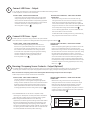
• For retrofit, place LED driver in the location where the ballast was formerly located.
• Make output (DC) connections as noted below:
OPTION 1 (OEM) – USING 4-WAY CONNECTOR
Connect the LED Driver output leads to the LED Light leads
using the appropriate mating connector (Molex P/N 39-014046). Terminals installed should be crimped using approved
tooling and process per Molex specifications. Ensure that the
connector cavities are correctly populated per the
wire cavity table on page 3. A
OPTION 2 (OEM or RETROFIT) – USING TWIST-ON WIRE
CONNECTORS
Remove the 4-way connector from the LED Driver by
cutting the wires near the connector and strip the output
leads. Using the appropriate wiring diagram on page 3,
connect the LED Driver output leads to the LED Light leads
using wire connectors or other connection method approved
for low temperature usage and stranded cable. A
For non-dimming applications, cap the unused wires with
5/32” (4mm) twist on wire connectors.
Connect LED Driver - Input
• Make input (AC) connections using one of the two options below:
• The LED Driver is required to be reliably bonded to the protective ground conductor. B
OPTION 1 (OEM) - USING 3-WAY CONNECTOR
Attach the supplied green/yellow ground wire from the
LED Driver to a grounded metal portion of the door frame.
Connect the original Line and neutral wires (or Line 1 and
Line 2 wires for 240 nominal VAC) to the 3-way connector
for the LED Driver input wires using the appropriate mating
connector (Molex P/N 39-01-4030). Ensure that the
connector cavities are correctly populated per the
wire cavity table on p. 3. C
3
OPTION 2 (OEM or RETROFIT) – USING TWIST-ON WIRE
CONNECTOR
Attach the supplied green/yellow ground wire from the LED
Driver to a grounded metal portion of the door frame.
Remove the 3-way connector from the LED Driver by cutting
the wires near the connector and strip the input wires. Using
the appropriate wiring diagram on page 3, connect the
original Line and neutral wires (or Line 1 and Line 2 wires for
240 nominal VAC) to the LED Driver leads using twist lock
wire connectors or other connection method approved for
low temperature usage and stranded cable. Ensure that the
connector cavities are correctly populated per wire cavity
table on p. 3. C
Dimming /Occupancy Sensor Contacts – Output (Optional)
• To enable dimming operation and/or occupancy sensors you must connect leads from occupancy sensor or control system (normally open contact) to the purple and gray leads of the power supply and adjust dimming switch as shown below.
Note: connection of occupancy sensor to the dimming leads will reduce light output to 20% normal output.
• Make output (contact closure) connections as noted below:
OPTION 1 (OEM) - USING 4-WAY CONNECTOR
Connect the LED Driver dimming output leads to the
occupancy sensor or control system using the appropriate
mating connector (Molex P/N 39-01-4046). Terminals installed
should be crimped using approved tooling and process per
Molex specifications. Ensure that the connector cavities are
correctly populated per the wire cavity table on page 3. D
• The GEPS6500NCMUL-SY LED Driver is capable of step dimming from 100% power to 20% power when used with a normally open contact closure occupancy sensor system.
• When using the GEPS6500NCMUL-SY for dimming applications, the dimming switch setting must be switched to the left to enable the dimming feature. The following is the only recommended usage of occupancy sensors with the Immersion LED lighting system. Other methods, such as using occupancy sensors to switch the LED driver on and off is not recommended and will void the product warranty.
OPTION 2 (OEM or RETROFIT) – USING TWIST-ON WIRE
CONNECTORS
Remove the 4-way connector from the LED Driver by
cutting the wires near the connector and strip the output
leads. Using the appropriate wiring diagram on page 3,
connect the LED Driver dimming output leads to the
occupancy sensor or control system using wire connectors
or other connection method approved for low temperature
usage and stranded cable. D
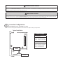
DIMMING
SWITCH
2
For Retrofit: Bundle and safely secure any unused wires by
way of approved wire ties and wire connectors.
Dimming
Dimming Enabled (20%)
Dimming Disabled (default)
DIMMING SWITCH