1
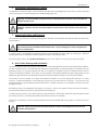
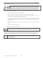
g
GEI M1010-A
GE Energy
Motor Installation
And Maintenance Instructions
Vertical AC Small Industrial Motors
NEMA 182 to 5011 Frame
NEMA Type P Base, Solid Shaft, TEFC
Normal Thrust and Aeration Pump Motors
© Copyright 2011 General Electric Company
2011/6/13
GEI M1010-A
Table of Contents
I.
General Information ................................................................................................................................................. 1
A. How to Properly Use this Instruction Manual ................................................................................. 1
B. Safety Symbols ............................................................................................................................................. 1
C. Safe Motor Operation Information ...................................................................................................... 2
D. Description of Labels and Nameplates ............................................................................................. 3
E. Model and Serial Numbers ...................................................................................................................... 3
F. Relevant Industry Standards .................................................................................................................. 3
II.
Receiving ....................................................................................................................................................................... 3
A. Unpacking ....................................................................................................................................................... 3
B. Temporary Storage ..................................................................................................................................... 4
C. Extended Storage ........................................................................................................................................ 4
D. Handling .......................................................................................................................................................... 4
III. Installation .................................................................................................................................................................... 4
A. Location ........................................................................................................................................................... 4
B. Mounting.......................................................................................................................................................... 5
C. Power Supply and Connections ............................................................................................................ 6
IV. Operation…………………………………………… .................................................................................................................... 6
A. Steps Prior to Starting ................................................................................................................................ 6
B. Initial Start ....................................................................................................................................................... 7
C. Jogging and Repeated Starts................................................................................................................. 8
V. Maintenance ................................................................................................................................................................ 8
A. General ............................................................................................................................................................. 8
B. General Cleanliness .................................................................................................................................... 8
C. Division 1 Explosion Proof Motors ........................................................................................................ 8
D. Insulation and Windings .......................................................................................................................... 8
E. Vacuum and Compressed Air Cleaning ............................................................................................. 9
F. Cleaning with Water and Detergent.................................................................................................... 9
G. Anti-Friction Bearings and Lubrication .............................................................................................. 9
VI. Operational Difficulties ......................................................................................................................................... 11
VII. Failure ........................................................................................................................................................................... 12
VIII. Repair ............................................................................................................................................................................ 12
IX. Renewal Parts ........................................................................................................................................................... 12
X.
Tightening Torque for SAE Hardware ............................................................................................................. 13
XI. Motor Lubrication Guide....................................................................................................................................... 14
© Copyright 2011 General Electric Company
GEI M1010-A
I. GENERAL INFORMATION
A. How to Properly Use this Instruction Manual
This installation and maintenance manual has been written to assist the user with proper procedures when handling,
installing, operating and maintaining the equipment. All of the safety warnings and instructions in this book must be
followed to prevent injury to personnel.
This manual must be kept for future reference during installation, operation and maintenance.
B. Safety Symbols
Below is a safety symbol table that identifies the safety symbols that appear in this manual and on the motors.
The use of a lightning bolt within an
arrowhead symbol, enclosed in a yellow
triangle warns of dangerous electrical
voltage that could cause an electric shock to
a person.
This symbol identifies a terminal, which
is intended for connection to an
external grounding conductor for
protection against electric shock in
case of a fault.
The use of an exclamation point within a
yellow triangle indicates to the user that
important installation, operating and
maintenance instructions must be followed.
The use of a small case “i” enclosed in
a square indicates a general note.
The use of wavy lines, enclosed in a yellow
triangle, indicates that the motor can be hot
and should not be touched without taking
proper precautions.
WARNING: if not strictly observed, could result in
This symbol instructs one to read the
manufacturer’s instruction manual before
installation, operation and maintenance.
CAUTION:
Indicates a procedure or condition that,
personal injuries or death.
Indicates a procedure or condition that,
if not strictly observed, could result in
minor injuries to personnel.
This symbol indicates the need to wear
hearing protection.
© Copyright 2011 General Electric Company
1
GEI M1010-A
C. Safe Motor Operation Information
WARNINGS: High voltage and rotating parts can cause serious or fatal injuries. Qualified
personnel should perform installation, operation and maintenance of electrical machinery. For
equipment covered by this instruction book, it is important to observe safety precautions to
protect
personnel from possible injury. Be sure to keep the installation and maintenance information for future reference. All
warnings and cautions must be followed.
Installation
• Avoid contact with energized circuits and rotating parts.
• Avoid bypassing or rendering inoperative any safeguards or protective devices.
• Avoid use of automatic-reset thermal protection where unexpected starting of equipment might be hazardous to
personnel.
• Avoid contact with capacitors until safe discharge procedures have been followed.
• Be sure the motor shaft key is captive before the motor is energized.
• Avoid long exposure in close proximity to machinery with high noise levels.
• When the motor is coupled to equipment, ensure that system vibrations are within acceptable limit (per ISO 108161) to avoid failure of the motor.
• Use proper protective gear, care and procedures when handling, lifting, installing, operating and maintaining the
motor.
• If eyebolts are used for lifting motors, they must be securely tightened, and the direction of the lift must not
exceed a 15° angle from the shank of the eyebolt. Do not use eyebolts in an ambient below 0°F. At temperatures
below 0° F, the eyebolt could fail resulting in injury to personnel and/or damage to equipment. Drop-forged
eyebolts per American Society of Testing Materials A489 or equivalent must be used.
• Do not use the motor shaft as a means for lifting.
• Do not lift both the motor and driven equipment with the motor lifting means.
• Do not stand on or place objects on the motor.
Maintenance
Safe maintenance practices performed by qualified personnel are imperative. Before starting maintenance
procedures, be positive that:
• Equipment connected to the shaft will not cause mechanical rotation.
• Main motor windings and all accessory devices associated with the work area are disconnected from electrical
power sources.
• The motor has been given time to cool.
Failure to properly ground the frame of the motor can cause serious injury to personnel. Grounding should be in accordance with National and local
Standards and consistent with sound practice.
These instructions do not purport to cover all the details in motors nor to provide for every possible contingency to be met in connection with installation,
operation or maintenance. Should further information be desired or should particular problems arise which are not covered sufficiently for the
purchaser’s purposes, the matter should be referred to the General Electric Company.
This document contains proprietary information of General Electric Company, USA and is furnished to its customer solely to assist that customer in the
installation, testing, operating and/or maintenance of the equipment described. This document shall not be reproduced in whole or in part, nor shall its
contents be disclosed to any third party without the written approval of GE Energy.
© Copyright 2011 General Electric Company
2
GEI M1010-A
D. Description of Labels and Nameplates
Motor rating and identification data are furnished on labels and nameplates. Packing nameplates provide a
permanent record of motor characteristics, plant identification and date of manufacture. Below is an example of a
label that is attached to the shipping package.
MOD – GE model number
KW = Motor power rating
RPM = Motor speed at full
load
VOL – Motor voltage
ENCL = Enclosure code
FR = Frame size
MASS = Motor mass
Figure 1: Packing Label
E. Model and Serial Numbers
As discussed in section D, every motor that is manufactured by GE Energy has a model and serial number, which are
permanently marked on the motor nameplate. When contacting a GE Energy Service Shop or representative, please
provide to the model and serial numbers.
Data and information regarding an individual motor model can be obtained from the Data Pack for the motor or
through EliteNet or by contacting your local GE Energy representative.
F. Relevant Standards
1.
Motors shipped with this installation instruction have been designed and built to the latest revision of the
following standards:
a.
2.
Motors that have the IECEx designation have also been designed to meet the requirements of the
following standards:
a.
b.
3.
NEMA MG-1
IEC and/or BS/EN 60079-0
IEC and/or BS/EN 60079-15
Motors with the CE Mark have also been designed to meet the requirements of the following EU
directives:
a.
b.
c.
d.
Machinery safety
Low Voltage
Electromagnetic Compatibility
Conformity Assessment
II. RECEIVING
Each shipment should be carefully inspected upon arrival. Motor rating and identification data are furnished on a
packing label for verification purposes. Any damage should be reported promptly to the carrier and a claim filed. The
nearest GE Energy sales office may provide additional guidance.
A. Unpacking
If the motor has been exposed to low temperatures, unpack it only after it has reached the temperature of the room in
which it will be unpacked. Otherwise the motor windings will be exposed to condensing moisture.
© Copyright 2011 General Electric Company
3
GEI M1010-A
B. Temporary Storage (Up to 6 Months)
If the motor will not be put into service immediately, certain precautions should be taken to protect the motor while in
storage. It is recommended the motor be placed under cover in a clean, dry location.
During storage, windings should be protected from excessive moisture by some safe and reliable method of heating,
such as space heaters, to keep the temperature of windings above the temperature of the surrounding air. It is
recommended the motor in storage be inspected at periodic intervals, the windings meggered and a log kept of
pertinent data. (Refer to the OPERATION section.) Any significant drop in insulation resistance should be investigated.
Precautions are taken by the factory to guard against corrosion. The machined parts are coated to prevent rust
during shipment. If the equipment is to be stored, examine the machined parts carefully for rust and moisture and
recoat where necessary.
The bearings of grease-lubricated motors are greased at the factory with the grease cavity approximately 50% full.
Rotate the shaft of all grease-lubricated motors 10-20 revolutions at two-month intervals.
If the purchaser has specified the machine be packaged for long-term storage, the foregoing recommendations do
not apply and the packing should be left intact during the period of storage.
C. Extended Storage (Longer than 6 months)
In the event the motor is to be stored longer than six months, please refer to GE instruction manual GEK-97427.
D. Handling
WARNING: Lifting lugs on the motor are designed for handling only the motor. They are not to be
used to lift the motor plus additional equipment such as pumps, compressors or other driven
equipment. In the case of assemblies on a common base, lugs or eyebolts provided on the motor are
not to be used to
lift the assembly and base. The assembly should be lifted by a sling around the base or by other lifting means
provided on the base. In the case of unbalanced loads (such as couplings or other attachments), additional slings
or other effective means should be used to prevent tipping.
III. Installation
WARNING: Installation should be in accordance with the ‘USA-National Electric Code’ or ‘BS/EN 602041’ and ‘BS/EN 60204-11’ and consistent with sound National and local practices. Coupling, belt and
chain guards should be installed as needed to protect against accidental contact with moving parts.
Motors accessible to personnel should be further guarded by screening, guard rails, etc., to prevent them from
coming in contact with the equipment.
A. Location
Install the motor in a well-ventilated area. Make sure there is a minimum clearance of one foot around the motor to
allow normal flow of air.
1.
Drip-proof motors are intended to be used in a well-ventilated place reasonably free of dirt and moisture.
2.
General Purpose enclosed motors can be used where they are exposed to dirt, moisture, and most
outdoor conditions.
3.
Severe-duty enclosed motors can be used in highly corrosive or excessively moist areas.
© Copyright 2011 General Electric Company
4
GEI M1010-A
4.
Zone 2 Hazardous Locations
All motors marked with an IECEx or ATEX designation are suitable for Zone 2 locations. Before the motor is installed in
the hazardous location, the marking must be reviewed for the intended location. If the motor marking does not meet
the intent of the location do not install or operate the motor. Refer to BS/EN 60079-0 and BS/EN 60079-15.
Motor marking for IECEx will have a nameplate with the IECEx logo, IECEx certification number, and IECEx marking
codes. An example of the IEC Ex marking is as follows;
Ex nA IIC T3 Gc
Where symbol:
a.
b.
c.
d.
e.
Ex provides assurance of protection per IEC standards.
nA indicates non-sparking
IIC is a code to indicate the type of explosive gas atmosphere.
T3 is a code for the maximum surface temperature.
Gc is a code for the motor protection level.
Refer to B/EN 60079-0 and BS/EN 60079-15 for the meaning and understanding of all symbols and codes.
5.
Division 1 Explosion-proof motors bearing the Underwriters’ Laboratories label designating the motor’s
Class and Group as defined in the National Electrical Code (NEC) are designed for operation in areas
classified by local authorities as hazardous in accordance with the NEC.
B. Mounting
1.
The System Reed Critical frequency should be 25% above or below motor operating speed in order to
avoid excessive vibration.
2.
Mount the motor on a firm, level base. For base assembly and motor mounting, the mounting bolts must
be tightened to prevent changes in alignment and possible damage to the equipment. It is
recommended that a washer be used under each nut or bolt head to get a secure hold on the motor
base. As an alternative, flanged nuts or bolts may be used. The recommended tightening torques for
medium carbon steel mounting bolts, SAE Grade 5, are listed below in Table 1. For recommended
tightening torques of other hardware on the motor see tables 4A, and 4B in the Tightening Torque section
of this book.
Table 1
Bolt Size
Inch
1/4
5/16
3/8
1/2
5/8
3/4
Metric
(M6)
(M8)
(M10)
(M12)
(M16)
(M20)
Recommended Torque
in Ft-Lb (N-M)
Minimum
Maximum
7
(9)
11
(15)
14
(19)
21
(28)
25
(34)
37
(50)
60
(81)
90 (122)
120 (163) 180 (244)
210 (285) 320 (433)
Note: For low carbon steel bolts, use 50% of the above recommended tightening torques. There are no ID marks on
low carbon steel bolts.
© Copyright 2011 General Electric Company
5
GEI M1010-A
3.
For direct coupled applications use flexible couplings if possible.
Accurate mechanical lineup is essential for successful operation. Mechanical vibration and roughness in
running the motor may be an indication of poor alignment. In general, lineup by straight edge across,
and feeler gauges between coupling halves is not sufficiently accurate. It is recommended that the
lineup be checked with a dial indictor and checking bars connected to the motor and load-machine
shafts. The space between coupling hubs should be maintained as recommended by the coupling
manufacturer. Shaft offset should not exceed 0.002”. Angular misalignment should be less than 0.002”.
4.
The application of pulleys, sheaves, sprockets, and gears on the motor’s shaft is shown in NEMA Standard
MG1-14.07. The application of the V-belts dimensions for alternating current motors is in MG1-14.42. Vbelt sheave pitch diameters should not be less than the values shown in Table 14-1 of NEMA MG-1.
Sheave ratios greater than 5:1 and center-to-center distances less than the diameter of the large sheave
should be referred to the Company. Make certain that the minimum allowed diameter of the motor
pulley and the maximum belt tension are not exceed because an excessive pull may cause bearing
trouble and shaft failures. Tighten belts only enough to prevent slippage. Belt speeds should not exceed
5000 feet per minute (25 meters per second). When V-belts are used, sheave ratios greater than 5:1 and
center-to-center distances less than the large sheave shall not be used. The dimensions of the belt pulley
are to be determined according to the kind of belt, transmission and capacity to be transmitted. Vent
holes have to be kept free and required minimum distances are to be observed in order not to obstruct
the flow of cooling air. In addition, make sure that the discharged hot air is not re-circulated into the
motor.
C. Power Supply and Connections
1.
Nameplate voltage and frequency should agree with the power supply. Motors will operate satisfactorily
on line voltage within ±10% of the nameplate value or frequency within ±5%, combined variation not to
exceed ±10%.
2.
Dual voltage motors can be connected for the desired voltage using instructions on the nameplate or the
connection diagram.
3.
Wiring of motor, control, overload protection and grounding should meet the National and Local codes.
4.
When mounting conditions permit, the conduit box may be rotated so that the conduit entrance can be
made upward, downward, or from either side. For oversize conduit boxes, the mounting height of the
motor may have to be increased for accessibility.
WARNING: Motor and control overload protection and grounding should be in accordance with
the USA -National Electric Code’ or ‘BS/EN 60204-1’ and/or ‘BS/EN 60204-11’ and consistent with
sound local practices.
IV. OPERATION
A. Steps Prior to Starting
WARNING: If the motor has been in a damp location, dry it out thoroughly before operating.
Before energizing the motor for the first time or after an extended shut down, it is advisable to
check the insulation resistance, power supply and mechanical freedom of the motor.
In accordance with established standards, the recommended minimum insulation resistance for the stator winding
when measured with a 500 volt DC direct indicating ohmmeter with self-contained power supply (megger), shall not
be less than 5 mega-ohms at 40°C for a motor rated under 1000 volts, and not less than 100 mega-ohms at 40°C for
a motor rated over 1000 volts. If the insulation resistance is lower than this value, it is advisable to eliminate the
moisture in one of the following ways.
© Copyright 2011 General Electric Company
6
1.
GEI M1010-A
Dry the winding in an air-circulating oven with the air surrounding the winding at 110°C, +5/-15°C until
the part has been above 90°C for at least four hours. Then the air temperature may be raised to 150°C,
+5°C/-15°C. Continue to heat until the insulation resistance is constant for a one-half-hour period.
2.
Enclose the motor with canvas or similar covering, leave a hole at the top for moisture to escape. Insert
heating units or lamps and leave them on until the insulation resistance is constant for a one-half hour
period.
3.
With the rotor locked mechanically and using approximately 10% of rated voltage, pass a current
through the stator windings. Increase the current gradually until the winding temperature reaches 90°C.
Do not exceed this temperature. Maintain a temperature of 90°C until the insulation resistance becomes
constant for a one-half hour period.
B. Initial Start
WARNING: Be sure the motor is not running and the power supply is disconnected.
Do not flush out anti-friction bearings. The bearing grease supplied is sufficient for initial operation.
1.
Whenever possible, examine the interior of the motor for loose objects or debris which may have
accumulated and remove any foreign material.
2.
If possible, turn the rotor by hand to be sure that it rotates freely.
3.
Check all connections with the connection diagram. Check all accessible factory made connections for
tightness to make sure none has become loose during shipment.
4.
When the driven load is likely to be damaged by the wrong direction of rotation, it is best to uncouple the
motor from its load during the initial start and make certain it rotates in the correct direction. If it is
necessary to change rotation, interchange any two line leads.
Some motors are designed for unidirectional rotation. Rotation of these motors must be in accordance
with the rotation indicated on the motor’s nameplate and the outline furnished with the equipment.
Connection plates on the motor have been furnished to assist in obtaining the proper rotation.
5.
After inspecting the motor carefully, make the initial start by following the regular sequence of starting
operations in the motor starter control instructions.
6.
At initial start, the rate of rise of the bearing temperature is more indicative of trouble than is total
temperature. When starting a machine for the first time, the bearing temperature should be observed for
a minimum of 2 hours. If at any time the rate of temperature rise exceeds 2°C/minute, shut down the
motor immediately and make an investigation of lineup conditions.
7.
For anti-friction bearings check motor operation under load for an initial period of at least one hour to
observe whether any unusual noise or hot spots develop.
8.
In the event of excessive vibration or unusual noise disconnect the motor from the load and check the
mounting and alignment.
9.
Check the operating current against the nameplate value. Do not exceed the value of nameplate current
multiplied by the motor service factor (if any) under steady continuous load.
10. Space heaters should be de-energized during motor operation.
© Copyright 2011 General Electric Company
7
GEI M1010-A
C. Jogging and Repeated Starts
CAUTION: Repeated starts and/or jogs of induction motors greatly reduce the life of the winding
insulation. The heat produced by each acceleration or jog is much more than that dissipated by the
motor under full load. If it is necessary to repeatedly start or jog a motor, it is advisable to check the
application with the local GE Energy sales office.
V. MAINTENANCE
WARNING: Before initiating maintenance procedures, disconnect all power sources to the motor
and accessories. For motors equipped with surge capacitors, do not handle the capacitors until
they are discharged by a conductor simultaneously touching all terminals
and leads, including earth. This discharge conductor should be insulated for handling. Replace all normal
grounding connections prior to operating.
A. General
If the motor is dismantled during maintenance, sealing compounds (if any) shall be removed from machined rabbets
(spigots). When reassembling the motor, all machined surfaces forming metal-to-metal joints should be sealed with
watertight sealing compound (Tite-Seal, GE Spec. A50CD427A or equivalent).
Inspect the motor at regular intervals, depending on service. Keep the motor clean and the ventilation openings clear.
In addition to the daily observation of the overall condition, it is recommended that a general inspection routine be set
up to check periodically the following items:
1.
General cleanliness
2.
Insulation and windings
3.
Lubrication and bearings
B. General Cleanliness
The interior and exterior of the motor should be kept free from dirt, oil and grease and conducting dust. Paper, textile
or dusts may build up and block off ventilation. Any of these contaminants can lead to early motor failure.
C. Division 1 Explosion Proof Motors
Division 1 Explosion-proof motors have special features and are manufactured in accordance with UL and carry its
label. Therefore, repairs need to be made at a GE Service Shop, which has been authorized to make such repairs.
D. Insulation and Windings
To obtain a long life and satisfactory operation of insulated windings, they should be kept clean from dirt, oil, metal
particles and other contaminants. A variety of satisfactory and acceptable methods are available for keeping the
windings clean. The choice of method will depend greatly on time, availability of equipment and on the insulation
system. Vacuum and/or compressed air cleaning with non-metallic hose tips should precede cleaning with water and
detergent or with solvents. Tightly adhering dirt will require removal by gentle brushing or wiping.
WARNING: To prevent injury to the eyes and respiratory organs, safety glasses and suitable
ventilation or other protective equipment should be used.
© Copyright 2011 General Electric Company
8
GEI M1010-A
E. Vacuum and Compressed Air Cleaning
Compressed air should be used to remove loose dirt and dust from air passages such as air ducts. Suction should be
used to remove dirt from the windings and to avoid damaging the coils.
CAUTION: Care must be taken to make sure the air is dry and that air pressure of not more than 21 x
103kg/m2 (30 psi) is used.
WARNING: Operator must not use compressed air to remove dirt or dust from his or her person and
clothing.
F. Cleaning with Water and Detergent
This method is very effective in cleaning windings when used with a low-pressure steam jenny maximum steam flow
30 psi and 90°C.
CAUTION: To minimize possible damage to varnish and insulation, a fairly neutral non-conductive
type of detergent such as DuBois Flow should be used. A pint of detergent to 76 liters (20 gallons) of
water is recommended.
If a steam jenny is not available, the cleaning solution may be applied with warm water by a spray gun. After the
cleaning operation, the windings should be rinsed with water or low-pressure steam.
Dry the windings. Refer to the Insulation Resistance section in IV A. above, for instructions on how to proceed.
G. Anti-Friction Bearings and Lubrication
The grease used as a lubricant in grease-lubricated anti-friction bearings does not lose its lubricating ability suddenly,
but over a period of time. For a given bearing construction and assembly, the lubricating ability of a grease over time
depends primarily on the type of grease, the size of the bearing, the speed at which the bearing rotates and the
severity of operating conditions. As a result, it is not possible to accurately predetermine when new grease must be
added. But, good results can be obtained if the general recommendations stated in this manual are followed.
The primary function of grease is to supply the essential lubrication oil from the sponge-like reservoir of its soap
structure. Grease-lubricated anti-friction bearings consume only a small amount of lubricant. This lubricant must
always be present to avoid rapid wear and bearing failure. However, excessive or too frequent lubrication may also
damage the motor.
Ball bearing motors are adequately lubricated at the factory. Motors with grease fittings should be lubricated in
accordance with these instructions to provide maximum bearing life.
To obtain optimum results, Exxon Mobil Polyrex EM (General Electric Specification D6A2C23) polyurea grease should
be used for lubrication, unless special grease is specified on the motor’s nameplate.
See Section XI Lubrication Guide for greasing frequency and recommended quantity of grease. If in doubt, refer to GE
Energy.
CAUTION: Failure to use polyurea base (NLGI Grade 2) or known compatible grease could result in
premature bearing failure.
© Copyright 2011 General Electric Company
9
GEI M1010-A
The procedure below must be followed for safe and effective re-greasing. The recommended frequency and quantity
of grease is stated in tables 5 and 6.
WARNING: Lubrication maintenance should be performed with the motor stationary and
disconnected from the power source. Extreme caution must be exercised to avoid contact with
rotating parts or electrical wiring if the motor must be lubricated while running. Extreme caution
must be exercised to avoid contact with rotating parts or electrical wiring if the motor must be lubricated while
running. Failure to observe these precautions may result in damage to the equipment, injury to personnel, or both.
1.
Run the motor until warm.
2.
Stop the motor and disconnect it from the power supply.
3.
Clean dirt and debris from around the inlet lubrication fitting and the grease relief plug.
4.
Remove the relief plug and clean the opening and relief tube of hardened grease.
accomplished with a twisted wire brush or sturdy pipe cleaner.
5.
Insert brush into the relief hole. While the motor is still warm, add grease with a hand-operated grease
gun until fresh grease appears on the end of the brush or until grease has been added up to the amount
listed in Table 6.
6.
Leave the relief plug temporarily off. Start the motor and run for 10 to 20 minutes to expel any excess
grease.
7.
Stop the motor. Replace the relief plug.
8.
Restart the motor and resume operation.
This may be
CAUTION: Failure to observe the foregoing instructions for re-greasing may result in grease leakage
and/or bearing damage. To avoid damage to equipment, bearings and grease must be kept free of
dirt.
Because this method of greasing bearings tends to purge the housing of used grease over a period of time, removal of
all grease should be required infrequently. A GE Energy Authorized Service Shop can clean the bearing cavity and
replace the bearings and grease when the motor is removed from service for maintenance or reconditioning.
NOTE: Warranty may be voided if internal maintenance or repairs are not performed by a GE Energy
Authorized Service Shop
© Copyright 2011 General Electric Company
10
GEI M1010-A
VI. OPERATIONAL DIFFICULTIES
Some operating difficulties may occur. Common causes are given in Table 2 and should be corrected as soon as possible.
TROUBLESHOOTING CHART
Table 2
Affected Parts
Difficulty
Windings
Overheating
Bearings
Overheating
Motor
Excessive Vibration
Winding Insulation
Low insulation resistance
or insulation failure
© Copyright 2011 General Electric Company
What to Check
Calibration of measuring instrument
Excessive Current
Unbalanced AC current
Improper or restricted ventilation
Excessive ambient temperature
Short circuited coil or windings
Dirty windings
Unbalanced voltage
Calibration of measuring instrument
Misalignment
Excessive end thrust or radial loading
Shaft currents
Excessive or insufficient grease
Worn out or dirty grease
Unbalance
Misalignment
System Reed Critical frequency too close to the motor
operating speed
Improper or settled foundation
Non-uniform air gap
Rubbing parts
Bent shaft
Unbalanced stator current
Damaged bearing
Moisture, dirt, metal particles, oil, or other contaminants on the
windings
Wrong voltage
Excessive temperature
Voltage surges
Mechanical damage
Excessive vibration with resultant mechanical damage
11
GEI M1010-A
VII. FAILURE
WARNING: An extreme overload or electrical failure may result in heating or arcing which can
cause the insulation to give off noxious fumes. All power should be removed from the motor
circuit as a precaution even though the circuit has overload protection. Personnel should not
approach the motor until adequate ventilation of the area has purged the air of fumes. When covers of a motor
are removed after a failure, care should be observed to avoid breathing fumes from inside the motor. Preferably,
time should be allowed for the motor to cool before attempting any examination or repair.
WARNING: Water should not be applied to any electrically energized equipment because electric
shock could result in serious or fatal injury. In case of fire, disconnect all power and use a carbon
dioxide extinguisher to quench the flame. Before operating any motor after a suspected failure,
it should be inspected for damage.
VIII.
REPAIR
If a motor is marked with IECEx or ATEX designation and repairs are required, the motor must be repaired by
operators trained in the understanding of BS/EN 60079-1 and BS/EN 60079-15 standards. The motor has been
designed to meet the rigid requirements of these standards. Repair or alteration of the motor may result in the motor
no longer meeting the requirements of these standards. If major repairs are undertaken (such as rewinding a stator),
proper facilities should be made available and suitable precautions observed.
Recommended tightening torques for various parts is listed in Tables 4A and 5B below.
WARNING: When burning off old insulation materials or when welding near insulation during
rewinding, adequate ventilation must be provided to avoid exposing personnel to noxious fumes.
Combustion of exhaust must be complete and adequately vented to the outside atmosphere in
compliance with acceptable standards.
Exposure of personnel to air-borne inorganic fibers must be avoided by adequate ventilation or by wetting the
remaining insulation components following the burning of the organic materials.
IX. RENEWAL PARTS
The use of only GE Energy renewal parts is recommended. When ordering, specify the model number and the serial
number of motor (complete nameplate data is desirable). Specify quantity and describe the part.
For information and service, refer to the nearest GE Energy Sales Office or a GE Energy Authorized Service Shop.
© Copyright 2011 General Electric Company
12
GEI M1010-A
X. TIGHTENING TORQUE FOR SAE HARDWARE
General Notes related to fasteners:
1.
2.
3.
Medium carbon steel fasteners per ASTM A449 Type 1.
Stainless steel fasteners per ASTM F593.
Threaded holes in parts for fasteners are per System 21, ASME/ANSI B1.3
Table 4A: Tightening Torque Range
Medium Carbon Steel SAE Hardware Grade 5 (Unless specified in below table)
Screw/Bolt Size
Typical Application
#10 (Low Carbon Steel)
1/4 in (Low Carbon Steel)
1/2 in
Bearing Cap
Bearing Cap
All Parts, except Bearing Cap and
Fan Cover
Fan Cover Mounting
Bearing Cap
All Parts, except Bearing Cap
Conduit Box Cover
All Parts, except Conduit Box
Cover
All Parts
3/4 in
All Parts
1/4 in
1/4 in Grade 8
5/16 in
5/16 in
3/8 (Low Carbon Steel)
3/8 in
Torque
(Inch-lbs)
15 - 25
35 - 60
Torque
(N-m)
1.7 – 2.8
4.0 – 6.8
70 – 96
7.9 – 10.8
100 - 145
78 - 120
170 - 250
180 – 240
11 – 16
8.8 – 14
19 – 28
20 – 27
250 – 370
28 – 42
610 – 920
70 – 100
2150 – 3200
240 – 360
Table 4B: Tightening Torque Range
Stainless Steel SAE Hardware Property Class 50
Bearing Cap
Torque
(Inch-lbs)
15 – 25
Torque
(N-m)
1.7 – 2.8
1/4 in
Bearing Cap
35 – 60
4.0 – 6.8
1/4 in
All parts, except Bearing Cap
60 - 75
6.8 – 8.5
5/16 in
Bearing Cap
78 – 120
8.8 – 14
5 /16 in
All parts, except Bearing Cap
130 – 155
15 – 18
3/8 in
All Parts
230 – 275
26 – 31
1/2 in
All Parts
550 - 670
62 – 76
5/8 in
All parts
1100 – 1340
120 – 150
3/4 in
All Parts
2000 - 2360
230 - 270
Screw/Bolt Size
Typical Application
#10
© Copyright 2011 General Electric Company
13
GEI M1010-A
XI. Lubrication Guide
(Excerpt from: GEK-72836E)
Table 5: Motor Lubrication Guide
Type of
Service
Standard
Severe
Very
Severe
Typical Examples
1 – 7.5
10 – 40
50 – 150
200 – 1000
Lubrication
Interval (Yrs.)
3
1
6 months
3 months
1 – 7.5
10 – 40
50 – 150
200 – 1000
1.5
6 months
3 months
1.5 months
1 – 7.5
10 – 40
50 – 150
200 – 1000
6 months
3 months
2 months
1 month
HP Range
Machine tools, air-conditioning
apparatus, conveyors (one or two
shafts), refrigeration machinery,
laundry machinery, oil well pumps,
water pumps
Motor for fans, MG- sets, etc., that
run 24 hours per day, 365 days per
year; coal and mining machinery;
motors subject to severe vibration;
steel mill machinery
Dirty, vibrating applications; where
end of shaft is hot (pumps and fans);
high ambient temperature
Table 6: Number of Grease Gun Pumps
Bearing Size on
Motor Nameplate
6205
6206
6208
6210
6213
Number of Pumps
16 Oz. Gun
24 Oz. Gun
(Approx. 475
(Approx. 700 mL)
mL)
5
3
6
4
10
7
25
17
35
23
6220
58
39
6309
6310
20
25
13
17
Bearing Size on
Motor Nameplate
6312
6314
6315; C 2315
6316
6318; NU 318
6320; NU 320; C
2320
6321
6324; NU324
Number of Pumps
16 Oz. Gun
24 Oz. Gun
(Approx. 475
(Approx. 700
mL)
mL)
40
27
50
35
65
45
60
40
75
50
95
65
153
246
102
164
NOTE: A standard 10,000 PSI (69 kPa) 16 ounce (475 mL) grease gun delivers approximately 0.04 oz. (1.18
mL) of grease with each pump, and a 24 oz. (710 mL) gun delivers approximately 0.06 oz. (1.77 mL) of
grease. The number of pumps listed represents approximately 20% of the total grease cavity volume in
end shield.
© Copyright 2011 General Electric Company
14
GEI M1010-A
Figure 3
Typical Solid-Shaft Normal thrust TEFC Motor
With Grease-Lubricated Ball Thrust And Guide Bearings.
Double Row Thrust Bearing On Left Is Used In All
Aerator Motors And In All 5011 Frame Normal thrust Motors
© Copyright 2011 General Electric Company
15