1
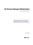
U S E R M A N UA L cooling tower motor I N S TA L L AT I O N - O P E R AT I O N - M A I N T E N A N C E M92-1475A I SSU E D 04/2013 R EAD AN D U N D E R STAN D TH I S MAN UAL PR IOR TO OPE RATI NG OR S E RVICI NG TH I S PROD UCT. installation RECEIVING AND STORING MOTORS INSTALLATION A motor should be inspected on receipt to make sure it was not damaged during shipment. Turn the shaft by hand to see that it turns freely. Check motor nameplate for correct horsepower, voltage, phase and speed. Check to see that the motor nameplate data agrees with the voltage and frequency of the power supply provided for the motor. All induction motors will operate successfully when the frequency is not more than five percent above or below the nameplate rating, the voltage is not more than ten percent above or below the nameplate rating, and the combined variation in voltage and frequency is not more than ten percent above or below the nameplate rating. If a motor is stored before installation, place it in a building in which air is kept reasonably dry and with a minimum of temperature fluctuation to prevent moisture condensing in the motor. Do not store directly on the floor, always block up. Windings should be meggered at the time the motors are put in storage. If motors have space heaters, the heaters should be ener‑ gized when the motors are placed in storage. NOTE: Remove units from containers when heaters are energized. Reprotect if necessary. If outdoor storage is necessary, protection should include a vapor barrier beneath the motor. The motor should be blocked up to prevent flooding. All external parts such as shafts, machined surfaces, and threaded holes should be protected with a rust inhibitor coating. Rotate motor shaft monthly to insure that the bearing surfaces are protected with lubricant. When a motor is removed from storage, the insulation and rotor movement should be checked. The insulation should be checked by applying the potential from a 500 volt meg‑ ohmmeter between the windings and grounded frame for 10 minutes. Resistance readings should be taken at 1 and 10 minutes. Correct the readings to 40°C as discussed on page 6 of this manual. Calculate the winding polarization index by dividing the 10 minute reading by the one minute reading. The recommended minimum value of polarization index for alternating current machine is: Class A insulation 1.5 Class B insulation 2.0 Class F insulation 2.0 A low polarization index indicates the insulation should be cleaned and dried before the motor is placed in operation. It is possible to operate a motor with a polarization value less than the minimum listed above but this is not considered good practice. The rotor movement is checked by rotating the shaft by hand. If shaft is not free, contact the motor manufacturer’s authorized repair shop. Grease in the motor bearings should be purged at the time of removal from storage. Refer to LUBRICATION on pages 5 and 6. The power supply line for the motor should be of sufficient capacity to carry 125 percent of the motor’s full load current with a maximum voltage drop of three percent on the line. The power supply MUST conform with motor nameplate voltage. Motors rated 200 volts are for a 208 volt sys‑ tem. Motors rated 230/460 volts are for a 240 or 480 volt system. Do not use a 230 or 230/460 volt motor on a 208 volt system. Unbalanced voltages in the power supply will greatly in‑ crease the internal losses of the motor, reducing the safe load the motor can carry. Have the power company correct any unbalanced voltage. When motor power is supplied by overhead conductors, it is advisable to provide a lightning arrestor on each un‑ grounded line. Wire the motor to the power supply through a disconnect switch, short‑circuit protection, and suitable magnetic starter with overload protection. All wiring and fusing should be in accordance with the National Electrical Code and local requirements. All motors should be connected as shown on the nameplate diagram. The National Electrical Code requires a motor to be in sight of the controller unless the disconnecting means can be locked open or unless there is a manually operated switch in sight of the motor which will disconnect the motor from its electrical supply. Overload protection should be installed in all three lines. Size overload heaters in starters for nameplate service factor and amps. Overloads for 1.15 service factor motors must kick out at no more than 125% of nameplate current. Overloads for 1.0 service factor motors must kick out at no more than 115% of nameplate current. Overloads should be at the same ambient temperature as motor. Do not use ambient compensated overloads. ➠ 3 installation – operation If a two-speed motor is used, be sure control characteristics are compatible with the motor. A two-speed single-winding motor requires a different starter than a two-speed twowinding motor. Starters for two-speed motors must include a minimum time delay of 20 seconds when switching from high to low speed. OPERATION When a disconnect switch is installed between motor and starter for two speed or part winding start single- speed motor, a 6‑pole disconnect must be used. Sleeve bearing motors are usually shipped without oil and must be oiled before operation. Ball bearing motors are lu‑ bricated for the initial operation by the motor manufacturer; however, it is recommended that the grease and relief plugs be removed and the motor bearing housing be examined for presence of adequate grease before motor is placed in operation. Add grease if necessary. See instructions on pages 5 and 6 for lubricating ball bearing or sleeve bearing motors. SAFETY NOTE: Use of two 3‑pole disconnects can result in one disconnect not being off and unexpected starts or motor damage. Turn the rotor by hand to see that it rotates freely. Motor shaft should be parallel to driven shaft so that there are no stresses in motor frame. If reverse operation of mechanical equipment is required, provide minimum time delay of two minutes before en‑ ergizing motor when changing direction of rotation. INITIAL STARTING: The motor should bring the fan up to speed in less than 15 seconds. If it does not, check connec‑ tions, fuses, overloads and voltage at motor terminals during start‑up period. Run the motor to check the connections and direction of rotation. If the rotation is incorrect, change any two of the three motor leads for a three phase motor or interchange the connections of either the main or start windings for single phase capacitor start motor. Check the wiring system for grounds and check the resistance between all leads for open, bad or incorrect connections before operating the motor. The conduit system should be arranged so that trapped water will collect in a sump equipped with suitable drain and will not go into the motor terminal box. When the motor must be moved for coupling removal or belt adjustment, a short section of flexible, watertight metallic conduit should be used in place of rigid conduit to protect the leads to the motor. Remove all water drain plugs from totally-enclosed motors. These plugs will be located in the lowest part of the installed motor. Because of inaccessability of drain plugs with motor installed on supports, it is sometimes necessary to remove plugs before the motor is bolted in place. The drain plugs on explosion-proof motors are automatic and must not be removed. NOTE: After motor is installed, it should be run for three hours at least once a month, even if the tower is not in operation. This serves to dry out windings and relubricate bearing surfaces. If motors are purchased with space heaters, they should be energized as soon as possible. Use an auxiliary contact on the starter to turn heater off when motor is running. CAUTION: Excessive fan cycling may shorten the mo‑ tor's expected service life. On fans 20 feet (6 meter) diameter and smaller allow for 4 to 5 starts per hour. On larger fans, 2 or 3 starts per hour may be the limit. On two speed motors each low speed start and each high speed start count as one start. If a two-speed motor is used, allow a time delay of a minimum of 20 seconds after de‑energizing the high speed winding and before energizing the low speed winding. Tremendous strains are placed on driven machinery and motor unless the motor is allowed to slow to low speed rpm or less before the low speed winding is energized. When changing fan direction of rotation, allow a minimum of two minutes time delay before energizing the fan motor. DETERMINE LOAD AT MOTOR: With design water rate and design heat load on the tower, test motor hp as follows: 1.Run motor for 30 minutes. Record motor name plate data. 2. Measure voltage between all lines at motor terminals. 3. Measure amps in all three lines. 4 operation – maintenance 4.Average the measured volts and amps and calculate test horsepower using the following equation: hp (test) = Volts x Amps (average) Volts x Amps (nameplate) x hp (nameplate) 5. For a given fan pitch setting and RPM, horsepower will vary directly with the air density which is a function of temperature and barometric pressure. Because fans are generally pitched for summer weather horsepower, it is expected that the motor nameplate horsepower will be exceeded during winter operation. Assuming 100% heat load, the temperature rise in the motor will be greater at the higher horsepower, but the operating temperature of the motor will actually be lower due to the drop in ambient temperature. Under these conditions, the higher horsepower should not be detrimental to the motor. If the horsepower measurement is taken during cold weather conditions, the predicted horsepower which will result during summer operation may be determined by applying the Factor from Figure 1. For a given location, the barometric pressure will not normally vary enough to cause significant error and for this reason, has not been included in the Factors. hp (75°F) = hp (40°F) X Factor (75°F) Factor (40°F) = 7.8 x 100.8 105.9 = 7.43 If it is desired to correct for high or low test barometric pressure, multiply the predicted horsepower by standard station barometric pressure and divide by test station barometric pressure. *Use ambient dry‑bulb temperatures if checking a forced draft cooling tower. Fan motor overloads sized for summer weather will handle the higher winter horsepower without adjustment providing they are at the same ambient temperature as the motor and there is ample heat load on tower. NORMAL OPERATION: Class B insulated motors are rated at a maximum total operating temperature of 130°C (266°F). A thermometer in contact with the winding may indicate a temperature up to 100°C (212°F). on a protected motor or up to 115°C (239°F) on a totally enclosed motor without the motor being too hot. Therefore, a motor that appears to be hot is not necessarily overloaded. Check with thermometers. CAUTION: Normal operating temperatures of electric motors can be hot enough to cause burns. Avoid any unprotected contact with the surface of an operating motor. 96 97 MAINTENANCE 98 SAFETY NOTE: When working on the fan or fan drive, make sure the electric motor cannot be started. See "Installation" section. 99 100 To obtain maximum motor life, establish a schedule of main‑ tenance based on the particular application of the motor and observe the following procedures and precautions: FACTOR 101 102 103 CLEANING: Remove any oil, dust or scale deposits from the motor. They can cause excessive insulation temperatures. 104 LUBRICATION: 105 Ball Bearing Motors: The following table may be used as a guide in determining greasing periods for motors: Figure 1 106 107 108 0 10 20 30 40 50 60 70 80 90 100 Example: The horsepower on an induced draft cooling tower* is 7.8 hp on a 40°F ambient wet‑bulb day. What is the predicted hp on a 75°F ambient wet‑bulb day? Duty 1 – 30 hp 40 – 250 hp I n te rm itte n t 12 m on ths 12 m on th s 8 to 16 h ou rs pe r da y 12 m on th s 6 m on th s Con tin u ou s 8 m on th s 4 m on th s 5 installation – operation All greases will deteriorate in time depending upon bearing size, speed and temperature. The grease used should be recommended by the motor manufacturer. See instructions attached to motor for recommended lubricant. If these instructions have been lost or misplaced, obtain informa‑ tion on lubricant to use and local supply source from motor manufacturer’s nearest authorized service facility or from the motor manufacturer. Give complete motor nameplate data and state clearly that the motor is used on a water cooling tower. Chevron SRI‑2 is recognized by many motor manufacturers as a suitable grease for ball bearing motors for cooling tower service. In general, a polyurethane or lithium base grease with rust and oxidation inhibitors is recom‑ mended. Use a grease of NLGI No. 2 consistency. Do not mix greases which are of different types or specifications. If a change is desired, the motor bearing housing grease reservoir should be completely cleaned of old grease before repacking with new grease. The relief method of greasing motors tends to purge the bearing housing reservoir of used grease by forcing out old grease with new grease. Use a plunger type grease gun which will not fit the bearing grease fill hole too tightly. race. If the bearing feels rough or binds in spots, it should be replaced. Sleeve Bearing Motors: Check oil in sleeve bearings at least every three months. When journal size is less than two inches, stop the motor to check the oil level. Old oil should be drained and replaced at least every year. Clean out oil well if there is evidence of dirt and sludge. Motor shaft must be stopped when motor is oiled. The oil used should be a good grade of mineral oil of light or medium viscosity (such as SAE No. 10). Turbine oil rather than automotive crankcase oil is recommended. Check bearing wear yearly by measuring the air gap with a feeler gauge. Measure gap in at least four equally spaced positions at each end of the motor with two of the places being the lowest point and the point subject to the load pull. INSULATION: Check insulation resistance with a meg‑ ohmmeter at the end of each shutdown period. Apply the megohmmeter potential to the winding for one minute before taking a reading. Correct the reading to 40°C by using the equation: R40°C= Kt x Rt and the curve below Either an excess or insufficient amount of lubricant in the bearings can cause overheating. To prevent this occurrence, use the following greasing procedure: 100 1. Stop motor. 50 3.Remove grease and relief plugs and free relief hole of any hardened grease. Use a thin piece of wire in open‑ ing. 4.Add grease with a hand operated pressure gun until new grease appears at the relief hole. Take special care when greasing the fan end bearing of TEFC motors. The long relief might be too small for the bearing to relieve properly. 5. Run the motor for approximately one hour after greasing to permit rotating parts of the bearing to expel excess grease. Take out some of the excess grease with a thin piece of wire. 6.Replace plugs and wipe the outside of the bearing housing clean. Every few years the motor end brackets should be removed and the grease reservoirs cleaned and repacked full with approved ball bearing grease. Open bearings should be cleaned and repacked. Bearings should be checked for "roughness" by turning the outer race slowly with the fingers while holding the inner 6 Insulation Resistance Temperature Coefficient Kt 2.Wipe grease plugs, outside of bearing housing, and relief plug, clean. 10 5 1.0 0.5 0.1 To Convert Observed Insulation Resistance Rt to 40°C Multiply by the Temperature Coefficient Kt , Rc – Rt x Kt 0.05 -10 0 10 20 30 40 50 60 70 80 90 100 Winding Temperature °C Approximate Insulation Resistance Variation with Temperature for Rotating machines. maintenance A record of these corrected readings will show a trend in the insulation condition. It is considered good practice to recondition a winding if the resistance, having been high on previous readings, drops to near the recommended minimum value as calculated by: Megaohms = 1000 + Rated Voltage of Machine 1000 Motors in continuous operation will stay at a temperature sufficiently above ambient temperature to prevent conden‑ sation of moisture on and about the windings, even if the location is very humid. Idle motors, however, accumulate moisture readily which causes gradual deterioration of in‑ sulation. Where motors are idle for a long time, single‑phase heating or space heaters may be required to prevent water condensation. Check insulation resistance at least once a year with the motor at normal operating temperature. Comparison with several previous readings will give an indication of improve‑ ment or deterioration of insulating value. Readings, to have comparison value, should be taken under the same condi‑ tions (temperature, operating time since last shutdown, etc.). Low or falling resistance readings indicate the need for maintenance. Contact the nearest repair facility authorized by the motor manufacturer for repair service. VIBRATION: If vibration occurs, it should be corrected without delay. Use the following procedure to determine source of trouble: 1. Check motor mounting to see that fasteners are tight. 2. Disconnect motor from load and run motor separately. If motor still vibrates, rebalance rotor. 3. If vibration is in mechanical equipment*, check: a. Alignment of motor with mechanical equipment. b.Tightness of Geareducer, or belt driven components, mounting bolts. Do not start motor without determining that there will be no interference with free rotation of the fan drive. MOTOR WARRANTY Motor manufacturers’ warranties run for 12 months in service but not to exceed 18 months from date of manufacture. Mo‑ tor manufacturers warrant their products to be of the type and quality described, suitable for the service for which they are supplied, and free of defects in materials and workman‑ ship. Failures from causes external to the motor (e.g., single phasing, operation under prolonged or extensive overload, damage from handling, improper maintenance, use on other than the service for which supplied, defect in wiring to power supply, or deficiency or defect in controls) are not covered by the motor manufacturers’ warranties. If a motor failure occurs within the warranty period because of defect in material or workmanship, the motor manufacturer is liable and has the right to remedy the failure by adjustment, repair, or supplying a replacement motor F.O.B. his factory or authorized repair facility. In such event, the motor must be delivered to the nearest repair facility authorized by the motor manufacturer with notification that the motor is from a Marley product and that warranty consideration is requested. Prompt notification of such failure should be directed to a Marley sales representative. Motor manufacturers will not accept warranty obligation for repair of motors by other than their authorized repair facility nor warranty obligation for materials or workman‑ ship employed in making repairs. Repair shops, including authorized repair facilities, generally warrant their material and workmanship for a period of 12 months. Motor manufacturers’ warranties do not cover cost of dismounting, transportation to and from repair facilities, or remounting motors. c. Unbalance in drive shaft or fan. *Refer to service manuals for operating and maintenance recommendations. MOTOR OPERATION NOTE: SEASONAL SHUTDOWN 1.If overloads are adjustable, set at a higher value (+15%) for cold weather operation. Readjust for sum‑ mer operation. If a motor is used only seasonally, it should be cleaned and lubricated at the close of each season. Refer to motor manu‑ facturer’s recommendations for lubrication and maintenance instructions. At start of new season, make sure bearings are adequately lubricated before returning motor to operation. When tower is not in operation, the motor should be run for three hours at least once a month. This serves to dry out windings and relubricate bearing surfaces. Higher density of cold air at fan increases motor horsepower. If motor overloads will not allow fan motor operation at high speed in forward direction, one of the following might be done: 2. Operate motor (fan) in reverse (reverse 2 loads). 3. Operate two‑speed motor at low speed. 7 cooling tower motor user manual S PX C O O L I N G T E C H N O LO G I E S , I N C . 7401 W 129 STREET OVERLAND PARK, KANSAS 66213 USA P: 913 664 7400 F: 913 664 7439 [email protected] In the interest of technological progress, all products are subject to design and/or material change without notice ISSUED 04/2013 M92-1475A COPYRIGHT ©2013 SPX Corporation