1
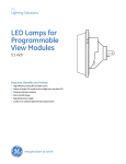
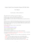
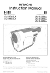
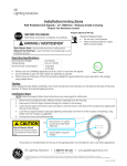
Installation Instructions GT1TM LED Pedestrian 16x18’’ Incandescent Look Signal Modules / PS7-CFF1-46A-J & PS7-CFF1-26A-J Full Hand/Person Overlay/Countdown BEFORE YOU BEGIN Prepare Electrical Wiring Electrical Requirements Read these instructions completely and carefully. Do not use in wet locations Follow all National Electric Codes (NEC) and local codes. Installation Steps: 1. 2. 3. 4. Verify input voltage is within specified range on the back of the LED signal module before installation. Failure to do so will cause lamp to fail. Open front cover of (customer supplied) traffic signal housing. Connect the wires to the appropriate terminal block within customer supplied signal housing. (Orange wire (+ for Hand), Blue Wire (+ for Person) and White wire (for the neutral). Close front cover of (customer supplied) traffic signal housing ensuring that the module gasket is tight within the housing. 16 x 18 inch Overlay / Countdown Risk of Electric Shock Install unit in enclosure tested to be suitable for wet locations only. Back of 16 x 18 inch Pedestrian Module Blue Wire White Wire Orange Wire Voltage Rating Countdown Option Jumpers (See next page) …Page 2 Installation Instructions (cont’d) GT1TM LED Pedestrian 16x18’’ Incandescent Look Signal Modules / PS7-CFF1-46A-J & PS7-CFF1-26A-J STEP A To Test Countdown Note: Module does not need to be disconnected from terminal block. 1. Remove Cap from "CONNECT TO TEST" 2. Connect jumper wire using appropriate screws. 3. Re-install Cap over jumper location To Stop Testing Countdown 1. Remove Cap from "CONNECT TO TEST" 2. Disconnect jumper wire and store it for future use (as shown on Figure A). 3. Re-install Cap over jumper wire STEP B To Disable Countdown Note: Module does not need to be disconnected from terminal block. 1. Remove Cap from "DISCONNECT TO DISABLE" 2. Remove jumper wire and replace screws for future use. 3. Re-install Cap over jumper location To Re-Enable Countdown 1. Remove Cap from "DISCONNECT TO DISABLE" 2. Re-install jumper wire using appropriate screws (as shown on Figure B). 3. Re-install cap over jumper wire. Risk of Electric Shock Step A: Connect Jumper wire to Test Countdown Install unit in enclosure tested to be suitable for wet locations only. Fig. A Step B: Disconnect Jumper wire to Disable Countdown Fig. B GE Lighting Solutions • 1-888-MY-GE-LED • www.gelightingsolutions.com 1-888-69-43-533 GE Lighting Solutions, LLC is a subsidiary of the General Electric Company. GT1 is a trademark of GE Lighting Solutions, LLC. The GE brand and logo are trademarks of the General Electric Company. © 2010 GE Lighting Solutions, LLC. Information provided is subject to change without notice. All values are design or typical values when measured under laboratory conditions. TRAF059-R120110