1
www. GEAppliances.com
Safety Information
..........
3
Operating/Care
and
Cleaning
Instructions
Charcoal
Filters ..............
Grease Filters ................
5
4
iV5 55
Hood Lights
................
Hood Surfaces
...............
Stainless Steel Surfaces
........
Vent Controls
...............
5
5
5
4
JV565
JV536
JV566
JV655
J17636
Installation
Customer
Instructions
...6-14
J17666
Service
Product Registration
Consumer
Support...
VVarrantv ..................
3q!665
..........
2
Back Cover
15
Patent No.: US D450, 829S
626851C
164D3333P240 49-80025-2 O7-O4JR
GE& You,A Service Partnership.
,0
IMPORTANT!
Fill out the Consumer
Product
Registration
Card.
Two easy ways to register your appliance/.
Through
Complete
the internet
and mail
at _v.geappliances.com
the enclosed
Product
Registration
Card
FORYOURRECORDS
Write the model and serial
numbers here:
,0
#
#
You can find them
on a label
on the back wall oI the hood.
Staple sales slip or cancelled
check here.
Proof
date is needed
of the original
imrchase
to obtain
service
m_(ler the warranty.
READTHISMANUAL
,0
Inside you will find many heli)ful hints on how to use and maintain
yore" range hood properly.
,Just a little preventive care on your part can save you a great deal of time and money over the
lif_" of your range hood.
/YYOUNEEDSERVICE
If you do need service, you can relax knowing help is only a phone call away: A list of toll-fl'ee
customer setMce nmnbet_ is included
in the back section of this manual.
OR
Visit our _'ebsite
at: vvww.geappliances.com
m
w
m
2
IMPORTANTSAFETYINFORMATION.
READALLINSTRUCTIONSBEFOREUSING.
SAFETY
PRECAUtiONS
WARNING
- To REDUCETHERISKOF
FIRE,ELECTRIC
SHOCKORINJURY TOPERSONS,
OBSERVETHEFOLLOWING:
A. Use this unit only in the rammer intended
b) the manufacturer. If )ou have questions,
contact the manufl_ctmer.
B. Be%re servicing or cleaning unit, switch
power off at service panel and lock the service
disconnecting means to pre_nt power flom
being switched on accidentally. When the
service disconnecting means cannot be
locked, securely filsten a prominent warning
device, such as a tag, to the service panel.
C. Do not use this unit with a W solid-state speed
control device.
WARNING
- To REDUCETHERISKOF
A RANGETOPGREASEFIRE:
A. Ne\>r leave sm_lce units unattended at high
settings. Boilovers cause smoking and greasy
spillovers that m W ignite. Heat oils slowly on
lo_a or medium settings.
B. Alx_:l)'sturn hood ON when cooking at high
heat or when cooking flaming foods.
C. Clean ventilating £ms flequently. Grease
should not be allowed to accumulate on tim
or filter.
D. Use proper pan size. Always use cook-ware
appropriate for the size of the surfime
element.
D. This unit must be g_ounded.
WARNING- TO
REDUCE
THE
RISK
OF
CAUTION-For general ventilating use only.
FIRE,ELECTRIC
SHOCKORINJURY TOPERSONS,
OBSERVETHEFOLLOWING:
Do not use to exhaust hazardous or explosive
materials and vapors.
A°
Installation work and electrical wiring must
be done by qualified person(s) in accordance
with all applicable codes and standards,
including fire-cated coIlstIuctioIl.
B°
Sufficient air is needed for proper
combustion and exhausting of gnses through
the flue (chimney) of tirol burning
equipment to prevent back drafting. Follow
the heating equipment manu_ctmer's
guideline and safety standards such as those
published by the National Fire Protection
Association (NFPA), and the American
Society for Heating, Refl'igecation and Air
Conditioning Engineers (ASHRAE), and
the local code authorities.
WARNING
- To REDUCETHERISKOF
INJURY TOPERSONSIN THEEVENTOFA RANGE
TOPGREASEFIRE,OBSERVETHEFOLLOWING*:
A. SMOTHER HAMES with a close-fitting
lid, cookie
sheet,
or metal
tray, then
turn
off
the burner. BE CAREFUL TO PREVENT
BURNS. If the flames do not go out
immediately, E\ A(_ UATE AND CAI _L
THE FIRE DEPARTMENT.
B. NEVER PICK UP A FI AMING PAN
You may be burned.
C. DO NOT USE WATER, including wet
dishcloths or towels--a violent steam
explosion will result.
D. Use an extingldsher
C. When cutting or drilling into wall or ceiling,
do not damage electrical wiring and other
hidden utilities.
ONlYif:
1. You kno_a you have a Class ABC
extingldshe_; and you aheady know how
to operate it.
2. The fire is small and contained in the
area where it started.
3. The fire department
D. Ducted i_ms must alwa) s be vented to the
outdoors.
WARNING- To REDUCETHERISKOF
FIRE,USEONLYMETALDUCTWORK
to repair or replace any
part of your hood unless it is q)ecifically
recommended
in this guide. All other
servicing should be referred to a qualified
technician.
Do not attempt
is being called.
4. You can fight the fire with )our back to
an exit.
* Based on "Kitchen Firesafet) Tips" published
by NFPA.
READANDFOLLOW
THISSAFETY
INFORMAtiON
CAREFULLY.
READAND SAVETHESEINSTRUCTIONS
3
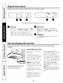
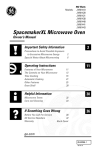
Usingthe hood controls.
Throughout this manual, features and appearance may vary from your model.
_!i_
i )i_i_i:_i_i_i_i_i_i_i_i_i_i_i_i_i_i
_!ii_i_ _(_!_i
I
Yourmodel will have one of the above type of controls.
0
FAN Control
Turn or press
speed control
LIGHT Control
Turn or press (according to your model) the
LIGHTcontrol to BRIGHTtor bright light while
cooking. Ttu'n or press to NITEfln" use as a night
light.
(according
to your model) the FAN
to LO, MED, HI or BOOST, as needed.
Cont.intlotls
rise of the
helps kee I) the kitchen
humid. It also reduces
moisture
that create a
tan sx:stem while cooking
comflwtable
and less
cooking
odors and soiling
fl'equent
need fin" cleaning.
@
FAN ON Light
The FANON indicator
tan is turned
light will glow when
the
on.
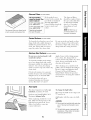
Careand cleaning of the venthood.
Be sure electrical power is off and all surfaces are cool before cleaning or servicing any part of the
vent hood.
Reusable Metal Grease Filters
The
hood
grease
has 2 metal
reusable
filters.
The metal filters trap grease
released
by fl)ods on the cooktop.
They also hel I) prevent flaming
foods on the cooktop
from
i::7.::!
_:"::
To clean the grease filters,
them and then swish them
in hot water
Don't
tlse
and
_llillilOlli_l
soak
around
detergent.
oY
_llillilOlli_l
products
because
they will darken
the metal. Do not use abrasives or
d_m_,_in_
theinside,,_
_heh,,,,d
oven cleaners,
i,ight b_ushing
be used to remove embedded
For dfis reason,
Rinse, shake and let them d_w
betore
replacing.
They may
also be clemmd in an automatic
dishwasher.
the filters
inust
ALWAYSbe in place
hood
when the
The grease tilters
is used.
If it ever becomes necessary to replace
the metal grease filters, they may be
should be cleaned
or as needed.
ordered from your GE suppliec
To remove,
the rear
down
slide the filters
using
and
once a month,
to
the tab. Pull them
NOTE: Before cleaning, make sure. the
charcoal filters, if present, are uncllpped
and removed. See the Charcoal Filters
sectioi?.
O/l[.
To replace, slide the filters in
the fl'ame slot on the back of
the opening.
Push up and back
and then to the fl'ont to lock
into place.
4
can
dirt.
Charcoal Filters (onsomemodels)
The charcOai filters
cannotbe
The cnarcoal filters are chooed inside
of each reusable metal grease filter
If the model
The charcoal
is not
cleaned. They
vented to the outside,
mustbe replaced,
For 3O hOod mOdels, Order
air will be recirculated
thr°ugh
disl_°sable
For36 hOM models, Order
Kit no. wBO2Xl07Oa,
remme
odors.
the
tilt.-s
th.thelp depending
usage).
TheS
kitscan
beordered
NOTE: DO NOT rinse, or
put charcoal filters in an
automatic dishwasher
Painted Surfaces (on some
models)
To clean
use a hot,
surfi_ce,
on hood
sm,,ke and
from your GEsupplier.
the hood
filters
should be replaced
when
they are noticeably
dirty
or discolored
(usually
after 6 to 12 months,
damp cloth with a mild detergent
suitable fl)r painted
surfaces.
Use a
clean, hot, damp cloth to remove
soap. Dry with a dr 5 clean cloth.
Do
Dot
steel-wool pads or other
cleaners.
They will scratch
IlSe
abrasive
the surtace.
damp cloth
X*\]l)e with a clean, hot,
after using cleansers.
Stainless Steel Surfaces (onsomemodels)
Do not
scratch
use
the
a steel-wool
surface.
To clean the stainless
use a hot, damp cloth
detergent
suitable for
surfaces.
Use a clean,
cloth to remove soap.
clean cloth.
pad;
it will
steel surface,
with a mild
stainless steel
hot, dalnp
Dry with a dry;
If fl)od soil remains,
ti T a general
kitchen
cleane_; such as Fantastik <_,
Simple Green_ or Form ula 409<'!
Apply cleaner with a damp sponge.
/_.rse a clean, hot, damp cloth to
remove cleaner. Dry with a dry, clean
cloth. Always scrub lightly in the
direction
of the grain.
After cleaning,
use a stainless steel
i)olish, such as Stainless Steel Magic:,
Revere Coi)i)er and Stainless Steel
Cleaner > or _,Venol All Pm'l)ose
Metal Polish i Follow the product
instructions
fl)r cleaning
the stainless
steel sm'tace.
For hard-to-clean
soil, use a
standard
stainless steel cleaner,
such as Bon-Ami <'_or (_aineo<'_
Hood Lights
This hood
included),
requires
two bulbs (not
maxim um 50 watts.
Pro'chase and install PAR20,
Maxim um halogen bulbs.
To change
[]
(;rasp
the bulb
tmscrew
it.
[]
Replace
50 W
When replacing
a bulb, let it cool
first. Make sure that power to the
light has been turned ott. Never
allow a hot bulb to coine into
c(mtact with water.
the light
bulbs:
on
the
with the same
edges
and
size bulb.
CAUTION:
Donot touchthehoodlightbulbswhenthey
areon. Theymaybe hotenoughtocause
injury
{ Thehghtbulbsoperateat extremelyhtgh
temperatures./f
theyshatter,thehotg/ass
couldcausepersonalinjury
5
RangeHood
Models JV535 JV635
JV536 JV636
JV565 JV665
JV566 JV666
Ilnstallation
nstruct,ons
Questions?visitour_vVebsite
at: www.geappliances.com
orCarlGEAnswer Center at 800.626.2000 [
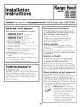
BEFORE YOU BEGIN
DUCTWORK
Read
NOTE:
these
instructions
completely
• IMPORTANT
instHwtions
fi)r local
- S.,ethese
inspector's
• IMPORTANT
governing
•
use.
- Obse,,e.ll
ordinances.
Note to Installer - Be sure to leave
instHwtions
with the Consmner.
• Note
codes
mad carefully.
to
ti)r fllture
- Kee I) these
these
• SMll level - Installation
of this appliance
basic mechanical
and electrical
skills.
" Product
covered
thihu'e
trader
is the responsibility
" Use only with approved
requires
to the
"Damage"
The
venting
system
cord
-
Before
of the
installation
is not
section
must
tufty if you
have
existing
do not
ductwork,
mad proceed.
exhaust
to the
outside.
upper
wall.
duct length:
For satistactory
air movement,
the total duct length
of a 3V(' x 10" rectangular;
6" or 7" diameter
rotmd
duct should not exceed 65 equivalent
feet.
kit, JXHC1.
begiIlIliIlg
sections
If you
If a 6" rotmd duct is required,
a rectangula>to-round
transition adaptor
must be used*. Do not use less thm_
a 6" dimneter
duct.
NOTE: It's important
that ducting be installed using
the most direct route and with as few elbows as possible.
This ensm'es clear venting of exhaust and helps prevent
blockages.
Also, mane sure dampers swing freely and
nothing is blocking the ducts.
FOR YOUR SAFETY:
WARNING
skip
Maximum
due to improper
the Warranty.
ductwork.
The hood exhaust has been designed to mate with
standard
3¼" x 10" rectangular
ducting or 7" diameter
rotmd ducting.
time - 1-3 horn's
• Proper installation
installeL
ductwork
existing
Exhaust connection:
instructions
reference.
• Completion
the
have
This hood can be xented verticall) through
cabinets or hofizoi_tallv throuoh
an outside
Ductwork is not included.
and
Consumer
Read
REQUIREMENTS
the
installation,
switch power off at service panel and lock
the service disconnecting
means to prevent
power
from being switched on acddentally.
When the service
disconnecting
means cannot be locked, secm'elv
tasten a prominent
warning
device, such as a tag,
to the setMce panel.
Elbows, transitions,
wall and roofcaps, etc.,
present additional
resistance
to airflow and are
equivalent
to a section of straight duct longer than their
actual l)hysical size. When calculating
the total duct
length, add the equi\:dent
lengths of all transitions
and
adaptors plus the length of all straight duct sections. The
charts on the fl)llowing pages show you how to calculam
total equivalent
ductwork length using the approximate
tibet of equiwdent
length of some t'},pical ducts.
* IMPORTANT:
If a rectangula>t(>
round transition
adaptor is used, the
bottom corners of the damper will
have to be cut to fit, using the fin
snips, in order to allow fl'ee
movement
of the dampeL
Equiwdent
lengths of duct pieces
are based on actual tests and reflect
requirements
perfl)rmance
6
fl)r good venting
with anv hood.
Installation
Follow the guidelines
DUCTING
fin" proper
duct sizing in the ducting
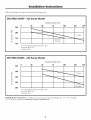
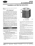
CHARTmJV5
Instructions
charts.
Series Models
EquivalentLengthin Feet
0
25
50
75
100
125
150
250
Z
L.L-
200
7" Round
E
o
150
31//' x 10"
Rectangular
100
3¼" x 10" RectangularTransitionto 6" Round= 4£ ft.
7" Round90° Elbow= 8 ft.
7" RoofCap= 30 ft.
DUCTING
CHARTmJV6
Series Models
EquivalentLengthin Feet
0
25
50
75
100
125
4OO
350
Z
7" Round
L.L-
300
E
250
Rectangular
200
3¼" x 10" Rectangular Transition to 6" Round = 4£ ft.
7" Round 90° Elbow = 8 ft.
7" Roof Cap = 30 ft.
MAXIMUM
DUCT LENGTH:
6" or 7" diameter
round duct
For satisfactory
air moxement,
should not exceed 65 equivalent
the total
feet.
7
dtlct length
of •a 3 J¼ " x 1n" rectangular,
150
Installation
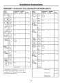
WORKSHEET--CALCULATE
DUCT
PIECES
Instructions
TOTAL EQUIVALENT
EQUIVALENT NUMBER
LENGTH
x USED
= TOTAL
3¼"x 10"
Rect.,
straight
1Ft.
x (
7" Round,
straight
1Ft.
6" Round,
straight
1Ft.
O
3¼"x 10"
Rect.90°
elbow
8.5Ft.
x (
)
=
Ft.
O
3¼"x 10"
Rect.45°
elbow
7Ft.
x (
)
=
Ft.
3¼"x 10"
Rect.90°
flat elbow
24 Ft.
x (
)
=
Ft.
3¼"x 10"
Rect.
wall cap
with
damper
45 Ft.
(7ft. w/o
damper)
x (
)
=
Ft.
x (
)
=
Ft.
3¼"x 10"
Rect.to
6" round
transition
4.5Ft.
3¼"x 10"
Rect.to
6" round
transition
90° elbow
11.5Ft.
x (
x (
)
=
)
=
)
=
DUCTWORK
DUCT
PIECES
EQUIVALENT
NUMBER
LENGTH
x USED
= TOTAL
6"Round
wall cap
with
damper
Ft.
Ft.
Ft.
LENGTH
x (
)
Ft.
x (
)
Ft.
6" Round 30 Ft.
roofcap
x (
)
Ft.
6" Round
to
3¼"x 10"
rect.
transition
x (
)
Ft.
6" Round 14.5Ft.
to
3¼"x 10"
rect.
transition
90° elbow
x (
)
Ft.
7" Round,
90°
elbow 8 Ft.
x (
)
7" Round, 6.5R.
x (
)
x (
x (
)
)
7" Round 30 Ft.
roofcap
x (
)
7" Round
5.5Ft.
x (
)
Ft.
7" Round 14.5R.
to
3¼"x 10"
rect.
transition,
90° elbow
x (
)
Ft.
34 Ft.
(6 ft. w/o
damper)
5.5Ft.
Ft.
(_
Ft.
45° elbow
x (
)
=
Ft.
Ft.
C_
wall cap
7"Round
with
damper
(6 ft.
34
Ft.
w/o
damper)
Ft.
Ft.
x (
)
=
=
(_
8 Ft.
x (
)
(_
45°
elbow
6" Round,
6.5Ft.
x (
)
Subtotalcolumn1
i/loveil/ent,
rectangular,
not
exceed
DUCT
the
total
<_
_,_
90° elbow
6" Round,
MAXIMUM
Ft.
LENGTH:
(h/ct
length
6" or 7" diameter
65 equivalent
For
satislthctorx
o_' a 3¼"
romid
duct
3¼"x 10"
rect.
transition
Ft.
=
Ft.
=
Ft.
to
air
Subtotalcolumn2
=
Ft.
Subtotalcolumn1
=
Ft.
Totalductwork
=
Ft.
x 10"
should
feet,
8
Installation
Instructions
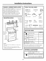
TOOLS YOU WILL NEED
DAMAGE---SHIPMENT/INSTALLATION
• If the unit
store
is dmnaged
in which
• If the unit
is dmnaged
replacement
• If the
tile
in shipment,
it was bought
is tile
customer),
must
customer
to tile
or
Flatbladeand Phillips
screwdrivers
customer;
(if other
or replacement
between
unit
repair
of tile
by the installer
repair
tile
or replacement.
by the customer,
responsibility
refit is dmnaged
by arrangement
return
fin" repair
and
Duct tape
than
be made
installe_;
Saw (saber or keyhole)
MOUNTING
Pencil
SPACE
Electric drill
Bottom edge of
cabinet needs
Metal snips
(in some
applications)
to be 30" or
_]
Z_-
|1
II
l]
_-,1
....
30" or 3B"
_
more
from
the cooking
surface
1/4" pivoting
hex socket
Pliers
Tape measure
Wire stripper
Flashlight
Caulking
Level
1/4" Nutdriver
3[
J
PARTS INCLUDED
PART
T
QUANTITY
Metal GreaseFilters
2
MountingScrews
4
(for3¼"
x 10" rect.venting)
ExhaustAdaptor
1
ExhaustAdaptorScrews
2
ExhaustAdaptor
(for7" roundventing)
1
NOTES:
• This range, hood
36" wide.
• If wm
are
going
outside,
see
exhaust
duct
tile
is fin" installation
to vent
"Ducting
yore" range
o',er ranoes_, up to
hood
Reqtfirements"
Sonle pails are shii}ped in tile hood behind tile filte_s.
On some models, tile bottom coxer of tile hood also
needs to be remoxed to gain access to tile parts.
to tile
section
for
preparation.
OPTIONAL
ACCESSORIES
Thesekitscanbe orderedfromyourGEsupplier.
I
orderKit
no.JXHC1.
CordKit--For
both30" and36" models,
CharcoalFilters--JV5 Seriesonly,if recirculating
For30" hoodmodels,orderKit no.WBO2X10707.
For36" hoodmodels,orderKit no.WBO2X10708.
9
Installation
Instructions
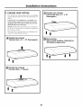
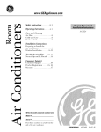
[] CHOOSE VENT OPTION
The
outside
requires
will use.
_ent
exhaust
will determine
option
the
hood
that
Outside
exhaust " x 10"
(Horizontalrearduct_31A
Rectangular)
yore" installation
knockouts
that
you
If the hood is to be hlstaJled in a recirculath_g,
nonvented ductless rammer, do not knock out any vent
opelfings in the hood. Only ml electrical access hole
will be knocked out of the hood.
NOTE: Only,IV5 Series models may be recirculated.
We do not recommend
the recirculated
configuration
tot IV6 Series models.
Detem_ine
the vent option
require fl'om the tollowing
that yore" inst_dlation
choices:
will
Outside
exhaust x 10" Rectangular)
(Vertical top
duct_3W'
I-_ Recirculating
(Non-vented
ductless_Optional
JV5 Series models only)
I-_ Outside top exhaust
(Vertical duct_7"
Round)
10
for
Installation
[] REMOVE EXHAUST
I),emo_e
tile
the
hood.
7" round
Set
ADAPTOR
exhaust
it aside
along
Instructions
adaptor
with
fl'om
the
its m o/mting
[] REMOVE OTHER EXHAUST ADAPTOR
top
ot
ReI/love
screws.
from
tile
inside
mounting
Inodel,
lett
[] REMOVE
ReIllOve
tile
FILTERS
shipping
tape
holding
filters
ill place. Pull down on tile
tile filters
out. Set theln aside.
tile
filter
metal
tabs
3¼"
tile
x 10" rectaaagulaJr
hood.
screws
the
or right
and
exhaust
exhaust
Set
it aside
along
parts
bag.
Depending
adaptor
adaptor
with
its
on
will be located
on
tile
the
side.
3V4"x 10"
3V4"x 10"
rectangular
rectangular
exhaustadaptor
exhaustadaptor
grease
and
lift
16_REIVIOVE WIRING
On
inodels
so equipped,
fl'onl inside
screw aside.
tile
hood.
COVER
relnoxe
Set
tile
tile
coxer
wiring
and
cover
its inounfing
Filters
Wiring
cover
[] REMOVE BOTTOM
()n
inodeJs
so equipped,
ti'om tile hood.
screws aside.
Set
tile
COVER
relno',e
co',er
and
tile
bottom
cover
its inounfing
[] REMOVE
Bottomcover
(heldin place
with 2
screws)
Remoxe
either
needed
and
WIRING
tile
install
Strain relief
clamp
11
top
an
or tile
approxed
KNOCKOUT
back
wiring
strain
knockout
refief
clamp.
as
Installation
[] REMOVE
Instructions
[]
DUCT KNOCKOUT(S)
FOR 31/4" X 10" RECTANGULAR
DUCTED DISCHARGE
INSTALLATIONS
ONLY:
If recirctdath_g,
non-vented
ductless (Ol_tional for
,IV5 Series models only), see uote below and skip to
Step 12 D and proceed.
We do not recommend
the
recirculated
configuration
for JV6 Series models.
Mtach exhaust adaptor/da_aper
over knockout
opening with two exhaust adaptor
screws. Make sure
damper pivot is nearest to top/back
edge of hood.
Remove tape ti'om damper
flap.
Using a fiat blade screwdriver;
remove the ai_i_ropriate
duct lmockout(s)
fi'om the top or back of the hood.
3'/4"x I0" Rectangular
vertical discharge•
Removetop rectangular
duct knockoutonly.
7" Roundvertical
discharge, Removesemicircularduct knockoutandtop
rectangularduct knockout.
Upto 1" side-tosideadjustment
Tape
Pivot
Exhaustadaptor/damper
(verticaldischargeposition
shown)
NOTE:
3'/4" x 10" Rectangular
The
up to 1 inch
aCCOlillilo(late
horizontal discharge• Remove
rear rectangular duct knockout only.
NOTE: If the hood is to be installed
in a recirculating,
non-vented
ductless manne_; order charcoal filters,
kit nmnber WB02X10707
fin" 30" hood models or
kit ntlillbeF WB02X10708
fin" 36" hood models.
on
adai)tor/damper
can
either
side of the
off=center
ductwork.
center
installations,
need
to be trimmed
[]
These kits can be ordered ti'om yore" GE sui_plie_:
Skip to Step 12 D mid proceed.
exhaust
one
end
to clear
of the
the
be installed
hood
center
]n extreme
duct
to
off =
connector
electrical
cable
may
clamp.
FOR 7" ROUND VERTICAL
DUCTED DISCHARGE
INSTALLATIONS
ONLY:
Re-install the 7" round exhaust adaptor with its
screws, removed
in Step 2 trader the "Prepare
the
Hood" section.
[] FOR HORIZONTAL DISCHARGE
INSTALLATIONS
ONLY:
Remove the plate (on models so equiI)ped ) in fl'ont
of the horizontal
discharge
knockout.
Cut the ties,
lift plate out and discard plate. DO NOT REMOVE
the metaJ strip held in place with two screws.
Metal strip
Ties
Screw
NOTE: The 7" rotmd
up to 1 inch on either
aCCOllllllodate
oItcenter
exhaust adaptor can be installed
side of the hood center to
dtlctwork.
In
exti'ellle
oItLcenter
instnllations,
one end of the duct connector
may need
to be trimmed to clear the electrical cable clamp.
NOTE: The 7" r(mnd damper is not included
with
this i_roduct. It can be i_m'chased as a kit b) calling
800.626.2002. Order kit nmnber,]'X[
A2..
12
Installation
[]
MARK HOLES
Select the xent option that _our installation
require and proceed
to that section:
A.Outside
top
(Vertical
Instructions
D.Recirculating
(non-vented ductless-Available on JV5 Series models only)
will
• Use the hood as a template
and mark rite locations
on the cabinet for the electrical
wiring and keyhole
screw slots.
exhaust
duct--31/4"
x 10" Rectangular)
• Since the hood is to be recirculated
(not to be vented
outside),
do not cut out am xent oi)enings, in the wall
or cabinet bottom.
• Use the diagran_ or the hood as a template
and
mark the locations
on the cabinet for ductwork,
electrical
wiring and keyhole screw slots.
Hood mounting screws (4)
[]
FOR RECESSED-BOTTOM
CABINETS ONLY
131_6" (30" hood)
(36"
I'
Wood shims(recessed- _"
Center
bottomcabinetsonly)
line
Electricalaccesshole {
(in cabinetbottom)
B.Outside top exhaust (Vertical duct--T'
• If the cabinets
have fl'ont, side or back trim, make
2 wood shims the width of the trim and attach them
Round)
• Use the diagram
or the hood as a template
and
mark the locations
(m the cabinet for ductwork,
electrical
wiring and keyhole screw slots.
to the cabinet bottom
recess
12 for marking
locations.
[]
Hoodmountingscrews(4)
wiring. For
toward the
duct fl'eely
installation
131%d
' (30" hood)
sides.
See Step
CUT HOLES
Cut holes
131_6"(30" hood)
hood)
on both
at marked
locations
for duct
and
electrical
the vertical duct, cut ()tit 3/4" extra
fl'ont of the cabinet so you can move the
when installing
the hood. It may also ease
by cutting the hole 10½" instead of 10".
101//'
Electrical access
hole (in cabinetbottom}
Wood shims (recessed- Center
line
bottom cabinets only)
[]
C.Outside
rear exhaust
(Horizontal
duct--31/4"
Run the electrical
wires through
the wall or
cabinet according
to National
Electrical
Code
and applicable
h)cal codes.
x 10" Rectangular)
• "Use the diagram or the hood as a template
and
mark the locations
on the cabinet for ductwork,
electrical
wiring and keyhole sc_'ew slots.
Wood shims (recessed-bottom
cabinetsonly)
[!_Cabinetl
7--7 ........
t
/'[
flCabinet
\
"_--_fr°nt
I
_/4"j___i___
y¢'
[bottom
NOTE: DO NOT mrn
installation
is complete.
'
[]
\
_--13 15>6" (30"hood)
\
-- 16_6" (36"hood}
\
Hood mounting screws (4)
_
_
_--51/4"
_
the power
on until
SCREW IN PARTWAY
Drixe a mounting
screw (from the hardware
packet)
partwa) into each center of the narrow neck of the
keyhole slots marked
on the cabinet bottom.
>'1 ,o_,zo,,r_,_oct
ITq_:_ I
±'
accessh,le
I
I_
I
I "--4
_51/4"
RUN WIRES
-_
15
13/16"(30"hood)
_,_ /
161_16"
(36"I_ood)
'
Electrical access hole
O0wall)
[]
FEED IN WIRES
I,ifl the It()()(] into position
and feed
IviI'i ng
throuoh_
the wirin,,_ knockout.
the house
Installation
[]
Instructions
[]
SECURE HOOD
CONNECT
WIRING
Connect
house black to hood black wire, house
white to hood white wire, and house grotmd
trader
green ground screw. Securely
tighten the strain
relief clamp onto the house wiring.
Slide the hood back against the wall. Tighten
the mounting
screws. Be sure the screw heads
are in the narrow neck of the keyhole slot.
ir0und screw
(4)
Keyhole(4)
NOTE: DO NOT PUSH ON E__N BI,ADE. Pushiw,
on the blade ma_ cause it to interiere
with other
hood
[]
[]
parts.
CONNECT
HOOD
DUCTWORK
Use duct tape to make joints
COVER
replace
the wiring
coxer
TO
secm'e and air tight.
[]
Ducttape
[]
REPLACE WIRING
On models so equipped,
or the bottolU coxer.
REPLACE FILTERS
Make sm'e tan blade turns freel). The installation
is
complete.
Turn on power at set\ice panel, and test
fi)r proper
operation.
INSTALL LIGHT BULBS
Pro'chase and install
halogen bulbs.
two PAR20,
50 _\ maximum
TROUBLESHOOTING
CHECKLIST
]f the hood seems to be operating at high speed when
the control is not set on high, or if ventilation
seems
inadequate,
check the ti_llowing:
U_JKnockouts
not removed
from hood.
[]
FOLLOW
Complete
National
NOTE:
Connect
ELECTRICAL CODE
the electrical
wiring according
Electrical
Code and local codes.
This hood
house
must be pemmnently
wMng
(120 VAC) to hood
Damper
Reduced
to
blade not opening.
airflow because the duct
is too small
the duct length is too long.
The duct is blocked.
grotmded.
wiring.
U_JUndersized
14
or restrictive
wall or roof cap.
or
GERange Hood Warranty.
All warranty service provided by our Factory Service Centers
or an authorized Customer Care® technician. For service,
call 800.GE.CARES.
GE Will Replace:
One Ybar
From the date of the
original purchase
Service
trips
to your
Anypattof the range hood which tifils due to a (leiect in materials or workananship.
Dudng this full one-year warranty, GE will also provide, free of charge, all labor and
in-home
home
service
to teach
to replace
you how
the
delbctive
to use
Dmnage
to the product
or acts of God.
the product.
hnproper
Failure
used
h_staJlation,
of the product
for other
delivery
or maintenance.
if it is abused,
thaa_ the intended
misused,
purpose
part,
h_cidentaJ
defects
or
or used
Dmnage
caused
or consequential
with
by accident,
dmnage
caused
fire, floods
by possible
this applimlce.
caused
after
delivery.
commercially.
Replacement
breakers.
of house
fuses
or resetth_g
of circuit
This warranty is extended to the original purchaser and any succeeding owner for products purchased for home
use within the USA. In Alaska, the warranty excludes the cost of shipping or service calls to your home.
Some states do not allow the exclusion or limitation of incidental or consequential damages. This warranty gives
you specific legal rights, and you may also have other rights which vary from state to state. To know what your
legal rights are, consult your local or state consumer affairs office or your state's Attorney General
Warrantor. General Electric Company.Louisville, KY 40225
15
ConsumerSupport.
gEAppliancesWebsite
www.GEAppliances.co
Have a question or need assistance with your appliance? Try the GE Appliances _,Vebsite 24 hom_ a (la_;
any day of the year! For greater convenience
and faster se_Mce, you can now download Owner's Manuals,
order parts, catalogs, or even schedule service onqine. You can also "_sk Our Team of Experts .....
yo/tI"
questions,
and
so
tIl/tch
tilOl'e,,,
ScheduleService
Expert (;E repair
your comenience
business hom_.
www.GEAppliances.com
setMce is onlx one step awa) from your cloot; Get on-line and schedule your service at
24 hom_ am dm of the _ear! Or call 800.GE.(:ARES
(800.432.2737)
during n(mnal
RealLife DesignStudio
GE supports tile Uni\'et_al Design concept--products,
services
people of all ages, sizes and capabilities. _,\'e recognize tile need
mental abilities and impaim_ents.
For details of GE's/!nivet_al
design ideas for people with disabilities, check out our _,Vebsite
call 800.TDD.GEAC
(800.833.4322).
Extended Warranties
www.GEAppliances.co
and environments
that can be used by
to design fi)r a wide range of physical and
Design applications,
including kitchen
today. For tile heating impaired,
please
www.GEAppliances.com
Purchase a (;E extended
warranla, and learn about special discounts that are a_ailable while your warrant_
is still in efli_ct. You can i_urchase it on-line anytime, or call 800.626.2224
during nomml business hom_.
(;E ()msuiner
Home Set\ices will still be there after your warrant} expires.
PartsandAccessories
www.GEAppliances.co
Individuals
qualified to setMce their own appliances
can have parts or accessories sent directly to their
homes (VISA, MasterCard
and Discover cards are accepted).
Order on-line today, 24 hom_ every' day or
by I)hone at 800.626.2002
during not_nlal business houI_.
Instructions contained in this manual cover procedures to be performed by any user. Other servicing generally
should be referred to qualified service personnel Caution must be exercised, since improper servicing may cause
unsafe operation.
ContactUs
If you are not satisfied
including your phone
www.GEAppliances.co
with tile service you receive ti'om GE, contact us on our _.Vebsite with all tile details
ntlI/lbeI;
or wtJte to: General
Manager; Custotner Relations
GE Appliances,
Appliance
Park
I,ouisville, KY 40225
RegisterYourAppliance
Register
your
€onYenience!
Tinlely product registration
will allow t0r
prompt service tlndei" tile terms ofxotlr WaITaIItV,
should tile need arise.
You may also mail in tile pre-ptinted
registration
card included in tile I)ackin°_ material.
enhanced
your new applimlce
www.GEAppliances.co
COillil/tlnicatJon
on-line---at
and
Printed in the United States