1
g
GEH-5838A
GE
Lighting Solutions
INSTRUCTIONS
LUMINAIRE FILTR•GARD® H2
Figure 7
Figure 4
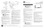
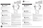
Wallmount Cover (See Figure 5)—Mount wiring box
and pull leads. Tether is supplied to hold arm assembly
while wiring. Wiring should be accomplished in accordance with accepted practices. Factory attached ground
lead is provided. After wiring, attach arm assembly to
wiring box. Do not damage gasket attached to arm assembly. Mounting screws should be tightened in alternate
sequence.
LAMP INSTALLATION
CAUTION
Risk of burn
• Allow lamp/fixture to cool before
handling
Use only lamps specified on nameplate. Observe
lamp manufacturer’s recommendations and restrictions on lamp operation, particularly ballast type,
burning position, etc.
Figure 5
Figure 6
Straight Stanchion Cover (See Figure 6)—Remove the
wiring box door. Attach mounting arm onto conduit.
Wiring should be accomplished in accordance with accepted practices. Factory attached ground lead is provided.
After wiring, replace the wiring box door.
Angle Stanchion Cover (See Figure 7)—Remove the
wiring box door. Attach mounting arm onto conduit.
Wiring should be accomplished in accordance with accepted practices. Factory attached ground lead is provided.
After wiring, replace the wiring box door.
WIRING
Make all electrical connections in accordance with
the National Electrical Code and any applicable
local code requirements.
Verify that supply voltage is correct by comparing it
to nameplate.
When changing voltage on reconnectable units,
move only the lead with the insulated connector.
IF SINGLE VOLTAGE:
All single voltage ballasts are pre-wired such that user
need only connect the supply conductors.
IF MULTIVOLT: (120/208/240/277 volts)
Connect the ballast lead with the insulated terminal to
the desired voltage terminal as indicated on the ballast
terminal nameplate.
IF MULTIWATT:
Multiwatt ballasts are available in various combinations
of wattage. See wiring instructions on wiring tag inside
the luminaire.
BALLAST HOUSING INSTALLATION
Slip ballast housing hinge pin over cover hinge. Mate
electrical connectors and swing unit shut. Tighten ballast
cover screw securely.
À LIRE AVEC SOIN AVANT D’INSTALLER
Lamp Tightness – Mogul Base Lamp: The lamp should
be securely inserted to the NEMA-EEI specified torque of 35
inch-pounds, which is best achieved by very firmly
tightening to insure application of sufficient torque.
Tightening must be sufficient to fully depress and load the
center contact of the socket.
Lamp Tightness – Medium Base Lamp: The lamp
should be tightened to a light firmness sufficient to depress
the center contact.
OPTICALS
CAUTION: GLOBE IS TEMPERED GLASS. DO NOT
SCRATCH OR CHIP.
Glass Globe—Attach globe by threading firmly into
bottom of ballast housing.
Industrial Reflector Type EN—Thread reflector firmly
into ballast housing. Lamp may be replaced via glass
clampband assembly.
Prismatic Refractor Assembly Type V, R or L—Thread
adaptor firmly into housing ballast housing. To orient
asymmetrical glass, loosen clamping screws, turn glass and
retighten screws. To relamp, unscrew complete optical
from ballast housing.
ACCESSORIES
External Reflectors—Insert mounting screws. Orient
reflector to proper position and slip over mounting screws.
Turn reflector and tighten screws securely.
Globe Guard—Insert protective guard into ballast
housing and turn until retained by detent.
MAINTENANCE
It will occasionally be necessary to clean optical assembly
in order to maintain light levels. Frequency of cleaning will
depend on dirt levels in user’s facility and minimum light
levels which are acceptable. Reflector should be cleaned
with any suitable non-abrasive solution of water and soap or
detergent. Residual cleaning agent should be removed with
clean water rinsing. Glassware may be cleaned with any
conventional glass cleaner. If unit gets soiled on inside, it
should be cleaned and any damaged gasket or filter replaced.
DA N G E R
Risque d’électrocution
• Mettre hors tension avant d’intervenir
– Suivez les instructions
LA TEMPÉRATURE NOMINALE“T-CODE” LISTÉE POUR CE
LUMINAIRE EST BASÉE SUR LES TAILLES D’AMPOULES
SUIVANTES. SI VOUS EN UTILISIEZ DE DIFFÉRENTES,
CELA POURRAIT AMENER UNE TEMPÉRATURE DE
FONCTIONNEMENT PLUS ÉLEVÉE ET PROVOQUER UNE
SITUATION DANGEREUSE.
TYPE DE LAMPE
TAILLE
SODIUM HTR PRESSION
SODIUM HTR PRESSION
HALOGÈNURE/MERCURE
HALOGÈNURE/MERCURE
COUVERCLE
PORTE BOîTE DE CÂBLAGE
DÉCONNEXION
RAPIDE
PUISSANCE
70,100,150
250, 400
175, 250
400
ED
ED
ED
ED
23 1/2
18
28
37
AVERTISSEMENT : COUPEZ L’ALIMENTATION
AVANT L’INSTALLATION OU L’ENTRETIEN.
PRÉSENTATION
DÉCONNEXION
RAPIDE
LOGEMENT DE BALLAST
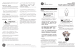
Schéma 1
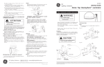
Couvercle flexible (Voir schémas 2 et 3)—Ôtez la porte de la
boîte de câblage. Desserrez les 4 boulons tenant l’axe de
montage sur le couvercle. Positionnez bien la plaque d’adapteur
pour équilibrer le luminaire. Utilisez l’écartement entre boulons le
plus grand possible pour fixer la plaque de couverture. Le
câblage doit être réalisé en conformité avec les pratiques
officielles. Une liaison de terre est fournie en sortie d’usine. Après
le raccordement refermez la porte de la boîte de câblage.
Un luminaire complet comporte un logement de ballast, un
assemblage optique et un couvercle/support.
RÉGLAGE
AXE DE MONTAGE
ATTENTION : Si vous installez ce luminaire dans des
BOÎTE DE CÂBLAGE
endroits dangereux, vérifiez la température limite de
fonctionnement avant de l’installer pour vérifier qu’il
compatible avec les restrictions de température de
l’environnement et les normes CEC.
COUVERCLE
PORTE BOÎTE DE
CÂBLAGE
INSTALLATION/MONTAGE
AT TENTION
DÉCONNEXION
RAPIDE
Schéma 2
LOGEMENT DE BALLAST
Risque de chute en cas de mauvais
montage • Suivez les instructions
Pendant (Voir schéma 1)—Ôtez la porte de la boîte
de câblage, et vissez le couvercle sur la conduite. Orientez
le couvercle, faites l’étanchéité autour du conduit en
utilisant des procédures approuvées. Serrez la vis de
blocage de l’axe de montage. Le câblage doit être réalisé
en conformité avec les pratiques officielles. Une liaison de
terre est fournie en sortie d’usine. Après le raccordement
refermez la porte de la boîte de câblage.
BOÎTE DE
CÂBLAGE
VIS DE TERRE
DISPOSITION pour:
Schéma 3
Couvercle de plafond (Voir schéma 4)—En utilisant les
pattes, montez le couvercle au plafond et enlevez la porte de la boîte de
câblage. Le câblage doit être réalisé en conformité avec les pratiques
officielles. Une liaison de terre est fournie en sortie d’usine. Après le
raccordement refermez la porte de la boîte de câblage.
Ces instructions n'ont pas pour destination de couvrir tous les détails ou variantes de l'équipement, ni de répondre à toutes les éventualités que vous pourriez rencontrer pendant l'installation,
le fonctionnement ou l'entretien. Si vous souhaitez des informations complémentaires, ou si vous rencontrez un problème particulier qui ne soit pas adressé de votre point de vue d'acheteur,
le sujet doit être remonté jusqu'à la société GE Lighting Solutions