1
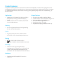
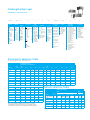
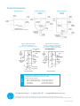
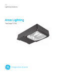
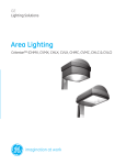
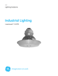
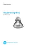
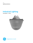
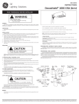
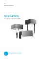
GE
Lighting Solutions
Area Lighting
Dimension™ (DMA, DMY & DMS)
imagination at work
Product Features
Designed for superior photometric performance and architectural appeal, GE Outdoor Area Sightlighters provide
broad application flexibility. From parking lots to downtown areas, hospitals to shopping malls, business complexes
to residential neighborhoods, these fixtures will satisfy your large area lighting needs, while complementing your
aesthetic desires.
Applications
Unique Features
•
•
•
•
•
•
•
•
Greater than 20 ft (6 meters) site lighting including parking areas, driveways, malls and shopping
centers
Commercial and industrial complexes, automobile lots and residential areas
Housing
• Precision engineered aluminum housing featuring die-cast ends and die-cast door
Finish
• Polyester powder paint finish standard in dark bronze, black, white, charcoal gray and aluminum
Rating
•
•
/
Listed Suitable for Wet Locations
Listed to Canadian National Standards and Codes
Mounting
•
Choice of mountings including Decorative
Mounting Arm (4 in. [103mm] or 12 in. [305mm]), Yoke or Spider (Drilling templates are the same for the Decashield™ 400 and Decashield™ 1000 luminaires.)
Reflectors
• All reflectors are field rotatable VT3 cannot be
rotated 180°
No-tool access stainless steel latch design
Heat and impact resistant tempered flat glass lens
Enclosed, sealed and gasketed housing
Removable ballast tray (standard)
Mogul base socket – E39 socket
Magnapack packaging available for DMA only
Ordering Number Logic
Dimension™ (DMA, DMY & DMS)
_ _ _
- __ - _
Prod. ID
wattage
DMA=
Dimension
Luminaire with
Arm Mounting
07 =70
10 =100
NOTE:
HPS only
DMY =
Dimension
Luminaire
with Yoke
Mounting
15 =150
(55V)
17 =175
25 =250
32 =320
35 =350
40 =400
01 =1000
DMS =
Dimension
Luminaire with
Spider
Mounting
Light
Source
E = Energy
Act Compliant
Pulse MH
(EPMH)
S = HPS
M = MH
P = Pulse
MH
Standard:
Mogul base
lamp not
included.
-
-
_
ballast
type
selection
Voltage
60Hz
0 = 120/208/240/
277 Multivolt
1 = 120
2 = 208
3 = 240
4 = 277
5 = 480
D = 347
F = 120X347
T = 220
50Hz
6 = 220
Y = 240
_ -
H =
M =
P =
NOTE:
120 X 347
connected for
120V
-
PE
Function
_
- ___ IES
Distribution
type
Lens
Type
1 =
2 =
4 =
See Photometric
None
G =Flat Glass
Selection Table
PE
Receptacle L =Polycarbonate
MC2 = Medium
PE
Prismatic
Autoreg
Cutoff Type II
Receptacle
Drop Lens*
Mag-Reg
and Shorting
(250W Max)
with
MC3 = Medium
Cap
Grounded
Cutoff Type III
S = SAG Glass
Socket Shell NOTE: Receptacle
HPF Reactor connected same *Contact
HTV = Horizontal
or Lag
Type V
voltage as unit.
Manufacturer
Mag-Reg
for photometric
CWI with
VT5 = Improved
distribution.
Grounded
Vertical Type V
(SC2 only)
Socket Shell
FWT = Forward
Throw
See Ballast and
Photometric
Selection Table
A =
G =
_
VT3 = Vertical
Type 3
__
-
_
-
_
Mounting
Arm Length
color
OPTIONs
AL =Aluminum 1 = 4 in.(102mm) for
Singles Two at 180°
BL =Black
DB=Dark Bronze 2 = 12 in. (305mm) for Two
at 90o Tri-Fixture Poles
(Standard)
Quad-Fixture Poles
CG=Charcoal
3 = 8 in. (203mm) for
Gray
singles or two at 180°
WH= White
4 = 4 in. (102mm) for
Round Pole
5 = 12 in. (305mm) for
Round Pole
6 = 8 in. (203mm) for
Round Pole
E = 2-3/8” External
Slipfitter
H = 10 in. (254mm) for
Round Pole Vertical
Hole Pattern
R = No arm. Housing
drilled with diagonal
hole pattern
X = Special
C = Charcoal Filter
(except on FWT
and VTV)
F = Fusing (Not
available
with multi-volt
or 120X347V)
J = Line Surge
Protector,
Expulsion Type
(UL not available)
Photometric Selection Table
All light sources are clear unless otherwise indicated.
Wattage
Light
Source
IES Distribution Type
Photometric Curve Number 35
DMA
MC2*
MC3*
VT3
HTV*
VT5
FWT*
70, 100
HPS
178871
178875 453659 178889 453664 178882
150 (55V)
HPS
178871
178875 453658 178889 453653 178882
250
HPS
178872
178887 453647 178878 453652 178883
400
HPS
178872
178887 453623 178878 453624 178883
750
HPS
N/A
N/A
453633 N/A
453632 N/A
175, 250, 320
EPMH 178873
178876 453665 178880 453670 178885
350, 400
EPMH 178874
178877 453677 178881 453682 178886
750
(BT 37 only) PMH
N/A
N/A
453635 N/A
453640 N/A
1000
(BT 37 only) MH
N/A
N/A
453641 N/A
453646 N/A
DMS
70, 100
150 (55V)
250
400
750
175, 250, 320
350, 400
750 (BT 37 only)
1000 (BT 37 only)
HPS
HPS
HPS
HPS
HPS
EPMH
EPMH
PMH
MH
179230
179230
179226
179226
N/A
179224
179278
N/A
N/A
179232
179232
179234
179234
N/A
179236
179275
N/A
N/A
453661
453656
453649
453628
453629
453667
453674
453637
453643
178934
178934
178935
178935
N/A
178937
178938
N/A
N/A
NOTE: *Lamp required for 400 watt MH must be E-18 or ED-28 only.
For Standard MH or PMH Lamp, you must order “S” SAG Glass lens type.
Consult Lamp Manufacturer Data for Horizontal Burning Pulse MH Lamps
453662
453655
453650
453627
453630
453668
453673
453638
453644
DMY
MC2
MC3
VT3
HTV
VT5
FWT
179229
179229
179225
179225
N/A
179223
179277
N/A
N/A
453660
453657
453648
453625
453634
453666
453678
453636
453642
179231
179231
179233
179233
N/A
179235
179276
N/A
N/A
178916
178916
178917
178917
N/A
178919
178920
N/A
N/A
453663
453654
453651
453626
453631
453669
453681
453639
453645
178928
178928
178929
178929
N/A
178931
178932
N/A
N/A
Ballast Selection Table
Wattage
Ballast Type/Voltage
60Hz
Light
Source Multivolt 120
70, 100, 150(55V) 250, 400
750
175, 320
250, 350, 400
750 (BT 37 only)
1000 (BT 37 only)
HPS
HPS
HPS
EPMH
EPMH
PMH
MH
A,H
A
N/A
A
A
A
A
A,G,H,M
A
A
A
A
A
A
50Hz
208, 240, 347,
277, 480 120X347 220
220
240
A,G,M
A
A
A*
A*
A
A
N/A
A
A
N/A
N/A
A
N/A
NOTE: C/F=Contact Manufacturer N/A=Not Available
H
A
A(347)
N/A
N/A
A(347)
A (347)
N/A
A
A
N/A
N/A
A
N/A
N/A
A
A
N/A
N/A
A
N/A
Product Dimensions
Arm Mounting
Spider Mounting
Yoke Mounting
24.000 in. SQ
(610 mm SQ)
2.375 in.
(60 mm)
24.000 in. SQ
(610 mm SQ)
2.000 in.
(50 mm)
6.500 in.
(165 mm)
11.688 in.
(297 mm)
23.000 in
2.000 in.
(50 mm)
2.375 in.
(60 mm)
11.688 in.
(297 mm)
26.073 in. R
(662 mm) R
m) R
11.688 in.
(297 mm)
29.992 in.
(762 mm)
23.000 in. R
(584 mm) R
840 in.
(21 mm)
Mounting Arm Choice of:
4.000 in. (102 mm) or 12.000 in. (305 mm)
3.000 in. (76 mm)
Maximum Pole
Top Tension
D ATA
4.392 in.
(112 mm)
3.000 in. (76 mm)
Maximum Pole
Top Tension
4.000 in.
(102 mm)
ROUND POLE MOUNTING
3.5 to 4.5-inch (89 to 114mm) OD
Round Pole Mounting Arm
(choices 4, 5, 6 from Logic Table)
.312 in. (6 mm) DIA Hole
.438 in. (11 mm) DIA
Holes
5.250 in.
(133 mm)
MIN
2.196 in. (56 mm)
1.250 in. DIA
(32 mm DIA)
HOLE
4.250 in.
(108 mm)
4.000 in.
(102 mm)
.312 in. (6 mm) DIA
Hole
.438 in. (11 mm) DIA
Holes
1.250 in.
(32 mm)
3.000 in. R
(76 mm) R
SQUARE POLE MOUNTING:
Diagonal Hole Pattern
(choices 1, 2, 3 from Logic Table)
5.250 in.
(133 mm)
MIN
1.812 in.
(46 mm)
2.375 in.
(60 mm)
23.350 in.
(590 mm)
3.000 in. R
(76 mm) R
. (584 m
2.000 in.
(50 mm)
1.812 in.
(46 mm)
2.719 in. (69 mm)
5.438 in.
(138 mm)
.750 in. DIA
(19 mm DIA)
HOLE
.656 in. (17 mm)
1.312 in. (33 mm)
DRILLING TEMPLATE
D ATA
DRILLING TEMPLATE
• Approximate Net Weight: 45-60 lbs (20-27 kgs)
• Suggested Mounting Height: 20-50 ft. (6-15 M)
• Effective Projected Area:
With 4 in. (103mm) Mounting Arm 2.2 sq ft max (0.20 sq M max)
With 12 in. (305mm) Mounting Arm 2.4 sq ft max (0.22 sq M max)
Yoke Mounted
3.8 sq ft max (0.35 sq M max)
Spider Mounted
2.9 sq ft max (0.27 sq M max)
GE Lighting Solutions • 1-888-MY-GE-LED • www.gelightingsolutions.com
1-8 8 8 - 6 9 - 4 3-533
GE Lighting Solutions, LLC is a subsidiary of the General Electric Company. The GE brand and logo are trademarks of the General Electric Company.
© 2012 GE Lighting Solutions, LLC. Information provided is subject to change without notice. All values are design or typical values when measured under laboratory conditions.
OLP-2947 (Rev. 10/29/12)