1
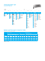
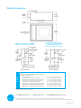
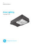
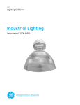
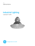
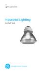
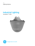
GE
Lighting Solutions
Area Lighting
Decashield ™ 1000 (DSA)
imagination at work
Product Features
Designed for superior photometric performance and architectural appeal, GE Outdoor Area Sightlighters provide
broad application flexibility. From parking lots to downtown areas, hospitals to shopping malls, business complexes to
residential neighborhoods, these fixtures will satisfy your large area lighting needs, while complementing your
aesthetic desires.
Applications
Unique Features
• High wattage site lighting including parking areas, roadways, automobile lots, tennis courts, malls and commercial complexes
•
•
•
•
•
•
•
•
•
Housing
• Precision engineered aluminum housing featuring
die-cast ends and die-cast door frame
Finish
• Polyester powder paint finish in dark bronze, black, gray, white or aluminum
Rating
•
/
1598 Listed Suitable for Wet Locations
Mounting
•
Decorative Mounting Arm (4 in. [103mm], 8 in. [203mm] or 12 in. [305mm]) (Drilling templates are the same for the Decashield™ 400 and Dimension™
luminaires.)
Reflectors
• All reflectors are field rotatable (90° increments)
No-tool access stainless steel latch design
Broken Glass Shutdown Circuit
Heat and impact resistant tempered flat glass lens
Removable ballast tray—standard
Utilizes standard 1000 watt lamps
Available with Type I, Type II, Type III or Forward Throw
Enclosed and gasketed housing
Mogul base socket – E39 standard
Magnapack packaging available
Ordering Number Logic
Decashield™ 1000 (DSA)
D
_ SA
__
- __ - _
-
Light
Source
Prod. ID
wattage
DSA =
Decashield
1000 Luminaire
with Arm
Mounting
75 = 750 S = HPS
01 =1000 M = MH
P = Pulse
MH
Standard:
Mogul base
lamp not
included.
_
-
Voltage
60Hz
0 = 120/208/240/
277 Multivolt
1 = 120
2 = 208
3 = 240
4 = 277
5 = 480
D = 347
F = 120X347
T = 220
_
_
-
ballast
type
selection
See Ballast and
Photometric
Selection Table
G
_
- ___ -
__
Lens
Type
IES
Distribution
type
color
-
PE
Function
1 = None
G = Flat Glass
2 = PE Receptacle
4 = PE Receptacle
and Shorting
Cap
A = Autoreg
H = HPF
Reactor or NOTE: Receptacle
Lag
connected same
P = CWI with
voltage as unit.
Grounded
Socket Shell
50Hz
6 = 220
R = 230
Y = 240
NOTE:
120 X 347
connected for
120V
-
_
-
Mounting
Arm Length
AL =Aluminum 1 = 4 in.(102mm)
for Singles
BL =Black
Two at 180o
DB=Dark Bronze
2 = 12 in.
(Standard)
(305mm) for
MC1 =
CG=Charcoal
Two at 90o
Medium Cutoff
Gray
Tri-Fixture
Type I *
WH= White
Poles
Quad-Fixture
SC2 =
Poles
Short Cutoff
3 = 8 in. (203mm)
Type II *
for Singles
Two at 180°
MC2 =
4 = 4 in. (102mm)
Medium Cutoff
for Round
Type II *
Pole
5 = 12 in.
MC3 =
(305mm) for
Medium Cutoff
Round Pole
Type III *
6 = 8 in. (203mm)
for round Pole
FWT =
R = No arm.
Forward
Housing
Throw *
drilled with
diagonal hole
* = Previously
pattern
IESNA Full Cutoff
Optics
See Ballast and
Photometric
Selection Table
Ballast and Photometric Selection Table
All light sources are clear unless otherwise indicated.
Ballast Type/Voltage
60Hz
IES Distribution Type
Photometric Curve Number 35-
50Hz
Wattage
Light
Source Multivolt
120, 208,
240, 277,
480
347,
120X347 220
220 230
240
MC1
SC2
MC2
MC3
FWT
750
1000
1000
1000 (BT37)
1000
1000 (BT37)
HPS
HPS
MH
MH
PMH
PMH
N/A
A
A, P
A, P
A
A
A,H
A
A
A
A
A
A,H
A
A
A
A
A
N/A
A
A
A
N/A
N/A
N/A
178993
N/A
N/A
N/A
N/A
178985
178986
178982
178987
178982
178987
NOTE: N/A = Not available
N/A
N/A
A
A
N/A
N/A
N/A
A
A
A
N/A
N/A
N/A
A
A
A
N/A
N/A
N/A
N/A
N/A
178978
N/A
178978
N/A
178980
178981
N/A
178981
N/A
178979
178988
N/A
N/A
N/A
N/A
_
OPTIONs
B = Time Delay
Automatically
Switched
Quartz
F = Fusing (Not
available
with multivolt or
120X347V)
J = Line Surge
Protector,
Expulsion Type
(UL not available)
Product Dimensions
2.375 in. (60 mm)
6.500 in.
(165 mm)
11.688 in.
(297 mm)
30.000 in. R (762 mm)
4.000 in.
(102 mm)
31.000 in. (787 mm)
24.000 in.
(610 mm)
2.250 in. (57 mm)
ROUND POLE MOUNTING
3.5 to 4.5-inch (89 to 114mm) OD
round pole mounting arm
(choices 4, 5, 6 from Logic Table)
SQUARE POLE MOUNTING: STANDARD
(choices 1, 2, 3 from Logic Table)
.312 in. (6 mm) DIA
Hole
5.250 in.
(133 mm)
MIN
1.812 in.
(46 mm)
.438 in. (11 mm) DIA
Holes
5.250 in.
(133 mm)
MIN
2.196 in. (56 mm)
4.392 in.
(112 mm)
1.250 in. DIA
(32 mm DIA)
HOLE
DRILLING TEMPLATE
5.438 in.
(138 mm)
DRILLING TEMPLATE
FOR ROUND POLES
DRILLING TEMPLATE
• Approximate Net Weight: 60-70 lbs (27-32 kgs)
• Suggested Mounting Height: 30-50 ft. (9-15 M)
• Effective Projected Area:
D ATA
2.719 in. (69 mm)
.750 in. DIA
(19 mm DIA)
HOLE
.656 in. (17 mm)
1.312 in. (33 mm)
.438 in. (11 mm) DIA
Holes
No Mounting Arm
Single with 4 in. (102mm) Mounting Arm
Double with 4 in. (102mm) Mounting Arm at 180°
Double with 4 in. (102mm) Mounting Arm at 90°
Single with 12 in. (305mm) Mounting Arm
Double with 12 in. (305mm) Mounting Arm at 180°
Triple with 12 in. (305mm) Mounting Arm at 90°
Quad with 12 in. (305mm) Mounting Arm at 90°
Double with 12 in. (305mm) Mounting Arm at 90°
2.6 sq. ft. max. (0.24sq. M max.)
3.0 sq. ft. max. (029 sq. M max.)
6.0 sq. ft. max. (0.56 sq. M max.)
4.5 sq. ft. max. (0.42 sq. M max.)
3.2 sq. ft. max. (0.30 sq. M max.)
6.4 sq. ft. max. (0.59 sq. M max.)
8.0 sq. ft. max. (0.74 sq. M max.)
9.3 sq. ft. max. (0.86 sq. M max.)
4.8 sq. ft. max. (0.45 sq. M max.)
NOTE: The wind loading of Decashield Luminaires, when mounted to poles in multiples radially about the axis of the pole, do not necessarily have the EPA of
a single luminaire multiplied by the number of luminaires.
GE Lighting Solutions • 1-888-MY-GE-LED • www.gelightingsolutions.com
1-8 8 8 - 6 9 - 4 3-533
GE Lighting Solutions, LLC is a subsidiary of the General Electric Company. The GE brand and logo are trademarks of the General Electric Company.
© 2012 GE Lighting Solutions, LLC. Information provided is subject to change without notice. All values are design or typical values when measured under laboratory conditions.
OLP-2943 (Rev. 06/19/12)