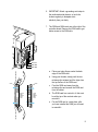
1
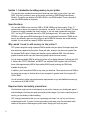
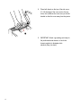
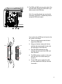
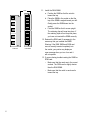
G CC TECHNOLOGIES RAM Installation Guide GCC Elite 12 Series and Elite XL 20 Series Laser Printers Contents: Section Section Section Section 1 2 3 4 - Introduction . . . . . . . . . . . . . . . . . . . . . . . . . . . . . Installing RAM into the Elite 12 Series . . . . . . . . . Installing RAM into the Elite XL 20 Series . . . . . . . Confirming RAM Installation and Updating Drivers . . . . . . . . . . . . .2 . . . . . . . . . . . . .3 . . . . . . . . . . . . .8 . . . . . . . . . . . .12 © Copyright GCC Technologies Inc., 2000. All rights reserved. Printed in USA. Part number 030.16481 Rev A. 1 Section 1 - Introduction to adding memory to your printer You can print more complex documents and download more fonts to your printer if you add RAM. To do this, you have to open up the printer and insert a SIMM (Single Inline Memory Module). The printer can hold up to 64 MB of RAM, in two SIMM sockets. There is already at least one SIMM installed in the printer. Specifications You can add SIMMs of any size from 2 MB to 32 MB. SIMMs must be non-parity 72-pin, 70 nanoseconds or faster, non-composite, symmetrical, low-profile, 5-volt, and tin leaded. This kind of memory is readily available from many sources, or you can order upgrade kits direct from GCC. Use only EDO (extended data out) or FPM (fast page mode). You cannot use DIMMs, SDRAM, or other special RAM technologies. Do not use gold plated connectors. SIMMs do not have to be installed in pairs, nor do you have to add a SIMM of the same size as that already installed. You can install any capacity SIMM in either socket. Why would I need to add memory to the printer? GCC printers ship with enough standard RAM to handle most print jobs at the largest page size and resolution supported by the printer. Some print jobs, however, may be more complex than the standard RAM is able to handle and therefore require additional RAM. Jobs with heavy graphical content and/or many font faces will typically require the most memory. You will reduce available RAM by setting the printer to Auto Switch between PostScript and PCL 5. Options like TCP/IP, WebAdmin, and NEST use additional RAM; together with Auto Switch, these utilize approximately 4MB of the available RAM, thereby reducing the RAM freely available for print jobs.. In addition, you’ll need printer RAM for any fonts you download. These require as much RAM as the space they occupy on the hard drive of your computer. In general, each font occupies 50 100k of RAM. You will continue to obtain minor performance improvements as you add additional memory up to a maximum of 64 MB of RAM. Required tools and safety precautions You should not need any tools to add memory to your printer. However, you should guard against static discharges. Your body can easily accumulate a static charge; if you touch a sensitive piece of circuitry, you can destroy it without realizing. GCC strongly recommends that you use a grounding wrist strap. You can buy one from any computer parts outlet. If you do not have a grounding wrist strap, touch the perforated metal chassis of the printer to discharge any static electric charge your body may have. 2 Section 2 - Installing RAM into the Elite 12 Series Printer 1. Switch off the printer. 2. Unplug the interface cables from the back of the printer. Do not unplug the power cord from the AC outlet. 3. If necessary, move the printer so that you have clear access to its left side. 4. Remove the paper tray. 5. Open the top cover by pressing the release button on the top right of the printer. 6. Remove the side cover. Unscrew the two thumbscrews at the rear of the printer (A). If these are tight, you may need to use a #2 Phillips screwdriver. C A B A 7. Reach inside the case. Pull the edge of the cover (B) toward you, then move the cover away from the rest of the printer to prevent it from latching again. B 3 8. Place both hands on the top of the side cover (C). Lift the edge of the cover next to the top cover; this unlatches the cover and you should be able to slide the cover away from the printer. C 9. IMPORTANT: Attach a grounding wrist strap to the perforated metal chassis, or touch the chassis regularly to dissipate static electricity from your body. 4 10. The ROM and RAM cards are at the right of the controller board. Remove the ROM card to get better access to the RAM slots. Note: Your controller board may vary from the one shown. Some Elite 12 models ship without a physical ROM card in place. If your printer has a ROM card in the slot to the left, remove it as follows: a. Place your index fingers under the back edge of the ROM card. Notch Notch b. Using your thumbs, slowly push the two retaining clips outward until the clips clear the top surface of the ROM card. c. Remove RAM SIMM or ROM Card Install RAM SIMM or ROM Card Pivot the ROM card away from the retaining clips and remove the ROM card from the socket. d. The ROM card has a notch in it; this must be at the top of the contacts when you reinstall it. e. Put the ROM card in a safe place; after you have installed the RAM you will need to reinstall it. 5 Notch ROM card 6 RAM SIMM 11. Install the RAM SIMM. a. Position the SIMM so that the notch is toward the top. b. Place the SIMM in the socket so that the top of the SIMM is angled toward your left. Gently press the SIMM down into the socket. c. Pivot the SIMM so that it moves upright. The retaining clips will snap into place. If the retaining clips will not snap into place, you have not inserted the SIMM correctly. 12. Reinsert the ROM card (if necessary) in the same way that you inserted the SIMM. Warning: If the RAM SIMM and ROM card are not correctly inserted completely into the socket, your printer may display an error message when you turn it on and it will not operate. 13. If you are having trouble inserting the SIMM or ROM card: • Make sure that the cards are in the correct sockets. The ROM card is slightly shorter than the RAM SIMM. • Make sure that the notch in each card is toward the top. 14. Remove the grounding wrist strap from the printer (if necessary), and reinstall the printer’s side cover. Don’t tighten the thumbscrews. Turn on the printer and wait to see if the control panel shows the “Ready” message. If it does, turn the printer off and go on to the next step. • If the “Ready” message doesn’t appear, turn off the printer and remove the cover. Gently try to rock the ROM card and SIMMs. If they are inserted correctly, they should not move. Carry out steps 11, 12 and 13 again, replace the cover and turn the printer on. • If the “Ready” message still doesn’t appear, and you are confident that you have installed the ROM card and SIMM correctly, contact GCC Technical Support at 781.276.8620 (U.S. only; outside the U.S. see back cover), www.gcctech.com, or your authorized GCC dealer. 15. If the printer is ready, tighten the thumbscrews (at the rear of the side cover) by hand. Make certain that the printer is switched off. Reinstall the interface cables (if necessary, insert the parallel port plug first). 16. Turn the printer on again. If the “Ready” message shows in the control panel, the physical installation succeeded. Now confirm the installation and update the printer driver on all computers that use this printer. See Section 4 of this guide. 7 Section 3 - Installing RAM into the Elite XL 20 Series Printer 1. Switch off the printer. 2. Unplug the interface cables from the back of the printer. Do not unplug the power cord from the AC outlet. 3. If necessary, move the printer so that you have clear access to its left side. 4. Remove the side cover. Unscrew the two thumbscrews at the rear of the printer, as shown. If these are tight, you may need to use a #2 Phillips screwdriver. 5. Slide the left cover assembly towards the rear of the printer. Swing out the bottom edge first and then lower the left cover out of the guide channel. LOC ALT RS - ALK 422 SCS I PAR ALL EL 10B ASE AAUI 8 -T 6. IMPORTANT: Attach a grounding wrist strap to the perforated metal chassis, or touch the chassis regularly to dissipate static electricity from your body. 7. The ROM and RAM cards are at the right of the controller board. Remove the ROM card to get better access to the RAM slots. LOC ALT RS - ALK 422 SCS I PAR ALL EL 10B ASE -T AAUI ROM Card RAM SIMM RAM SIMM a. Place your index fingers under the back edge of the ROM card. b. Using your thumbs, slowly push the two retaining clips outward until the clips clear the top surface of the ROM card. Notch Notch c. Remove RAM SIMM or ROM Card Install RAM SIMM or ROM Card Pivot the ROM card away from the retaining clips and remove the ROM card from the socket. d. The ROM card has a notch in it; this must be at the top of the contacts when you reinstall it. e. Put the ROM card in a safe place; after you have installed the RAM you will need to reinstall it. 9 Notch ROM card 10 RAM SIMM 8. Install the RAM SIMM. a. Position the SIMM so that the notch is toward the top. b. Place the SIMM in the socket so that the top of the SIMM is angled toward your left. Gently press the SIMM down into the socket. c. Pivot the SIMM so that it moves upright. The retaining clips will snap into place. If the retaining clips will not snap into place, you have not inserted the SIMM correctly. 9. Reinsert the ROM card in the same way that you inserted the SIMM. Warning: If the RAM SIMM and ROM card are not correctly inserted completely into the socket, your printer may display an error message when you turn it on and it will not operate. 10. If you are having trouble inserting the SIMM or ROM card: • Make sure that the cards are in the correct sockets. The ROM card is slightly shorter than the RAM SIMM. • Make sure that the notch in each card is toward the top. 11. Remove the grounding wrist strap from the printer (if necessary), and reinstall the printer’s side cover. Don’t tighten the thumbscrews. Turn on the printer and wait to see if the control panel shows the “Ready” message. If it does, turn the printer off and go on to the next step. • If the “Ready” message doesn’t appear, turn off the printer and remove the cover. Gently try to rock the ROM card and SIMMs. If they are inserted correctly, they should not move. Carry out steps 11, 12 and 13 again, replace the cover and turn the printer on. • If the “Ready” message still doesn’t appear, and you are confident that you have installed the ROM card and SIMM correctly, contact GCC Technical Support at 781.276.8620 (U.S. only; outside the U.S. see back cover), www.gcctech.com, or your authorized GCC dealer. 12. If the printer is ready, tighten the thumbscrews (at the rear of the side cover) by hand. Make certain that the printer is switched off. Reinstall the interface cables (if necessary, insert the parallel port plug first). 13. Turn the printer on again. If the “Ready” message shows in the control panel, the physical installation succeeded. Now confirm the installation and update the printer driver on all computers that use this printer. See Section 4 of this guide. 11 Section 4 - Confirming the installation of RAM These steps confirm that the printer recognizes the additional memory: 1. Switch on the printer. 2. Press the On Line button on the control panel; you’ll see the message “Off Line” in the display panel. 3. Press the Menu key four times; “Printer Info” appears in the display panel. 4. Press the Enter key; you’ll see the total amount of RAM that the printer recognizes. If this is the same as the new total of RAM, press the On Line key and the printer goes back on line. If this figure is not the same as the total amount of RAM, turn the printer off, and remove the side cover. Repeat from step 14 (Elite 12) or step 11 (Elite XL 20) in the previous steps, starting from “If the ready message doesn’t appear . . .” Updating LaserWriter 8 printer driver (Macintosh Only) After extra memory is installed, the LaserWriter 8 driver configuration must be updated on every Macintosh that uses the printer. 1. Switch the printer on. 2. Select the Chooser from the Apple () menu. 3. Click the LaserWriter 8 icon in the upper left area of the Chooser. You’ll see the name of your printer in the upper right area of the Chooser below “Select a PostScript printer.” If the name is not highlighted, click on it to highlight it. 4. Click on the Setup button. You’ll see the Setup dialog box. 5. Click on the Auto Setup button. You’ll see a message box telling you that the computer is communicating with the printer. 6. After a few seconds you’ll see the Setup dialog box again. Click the OK button to return to the Chooser, and then close the Chooser. 7. Repeat the preceding six steps on every Macintosh that will use the printer. 12 Updating Windows drivers (all versions) After you have installed extra memory you must update the Windows printer driver on every Windows computer that will use the printer. First, you need to carry out the next four steps once. This method works for all versions of Windows, and provides a memory figure for you to enter. 1. Switch the printer on. 2. Open a DOS Window by clicking on the MS-DOS prompt icon on the Windows 95/98 (or NT 4.0) Start menu, or the MS-DOS Prompt icon in the Windows 3.1 (or NT 3.51) Main Window. 3. Assuming that your printer is on LPT1 and that Windows is installed on the C drive, type the following: copy c:\windows\system\testps.txt lpt1: If your printer is connected to another port, or Windows is installed on a drive other than C, change the references. Do not use any Windows print commands; you must execute this command in DOS. 4. Type EXIT and press the Return key to return to Windows. The printer will have printed a page which shows “Max Suggested VM (KB):” This is the maximum suggested Virtual Memory for the printer in kilobytes. Now you need to enter this figure in the Printers section of Windows Control Panel on every Windows computer that uses the printer. The way you do this varies between versions of Windows. Windows 95/98 1. Choose Settings from the Start menu, and choose Printers from the submenu. 2. You’ll see the Printers window; use the right mouse button to click on the Elite 12 Series icon. 3. You’ll see a menu; choose Properties from this list. 4. You’ll see the Properties tabbed dialog box; click on the Device Options tab. 5. At the top of the dialog box is a section marked Available printer memory (in KB). Enter the suggested virtual memory into this box, and click OK. 6. Repeat the preceding five steps on every Windows 95/98 computer that uses the printer. 13 Windows NT 4.0 14 1. Choose Settings from the Start menu, and choose Printers from the submenu. 2. You’ll see the Printers window; use the right mouse button to click on the Elite 12 Series icon. 3. You’ll see a menu; choose Properties from this list. 4. You’ll see the Properties tabbed dialog box; click on the Device Options tab. 5. In the window, click on Virtual Memory. 6. Enter the suggested virtual memory figure into the box, and click OK. 7. Repeat the preceding six steps on every Windows NT 4.0 computer that uses the printer.