1
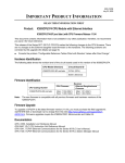
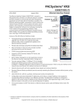
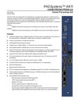
GFK-2123L June 22, 2005 IMPORTANT PRODUCT INFORMATION READ THIS INFORMATION FIRST Product: Series 90-30 CPU374 PLUS IC693CPU374-EK CPU Firmware Version 12.00 Ethernet Firmware Version 3.30 Release 12.0 of the CPU374 adds the following new features: SRTP Client Channels EGD Class 2 Device Support Web Server Support For detailed descriptions of the new features, refer to page 4. Release 12.0 also includes the following significant problem fix: Implementation of filtering for multicast Ethernet messages. For details on problems resolved, refer to page 4. Release 12.0 modules have an updated faceplate that includes the word PLUS. Hardware Identification The following table shows the revision level of the circuit boards used in this version of the IC693CPU374. CPU Model (Version) IC693CPU374-EK Circuit Board ID CY3A1 (CPU) EX3A1 (Ethernet) Firmware Identification CPU Catalog Number IC693CPU374-EK CPU Firmware Revision Ethernet Daughterboard Firmware Main: 12.00 (19A2) Boot: 12.00 (05A1) Main: 3.30 (19A1) Boot: 3.30 (16A2) Upgrades Hardware versions CPU374-Dx and earlier cannot be upgraded to this hardware or firmware release. CPU374 hardware that is not compatible with CPU374-EK can be upgraded via the Trade Up program. Contact your local GE Fanuc representative or distributor for details on the Trade Up Program Documentation Series 90™-30 PLC Installation and Hardware Manual, GFK-0356 Series 90™-30/20/Micro PLC CPU Instruction Set Reference Manual, GFK-0467 TCP/IP Ethernet for Series 90-30 CPU374 User's Manual, GFK-2382 TCP/IP Ethernet for Series 90-30 CPU374 Station Manager Manual, GFK-2383 Important Product Information (this document), GFK-2123L Important Product Information 2 GFK-2123L CPU Functional Compatibility HHP Compatibility Programmer Version Requirements C Toolkit Compatibility IC693CMM321 Ethernet Option Module Version Requirements FBC Compatibility Power Supply Compatibility and Requirements IC693ALG220/221 Analog Input Module Version Requirements IC693PBM200 PROFIBUS Master Module Version Requirements IC693PBS201 PROFIBUS Slave Module Version Requirements The CPU374 does not support the Hand Held Programmer. Proficy™ Machine Edition Logic Developer PLC 5.0 Service Pack 3 Hot Fix 3 or later must be used to configure Web Server support or to enable EGD Signatures. Machine Edition Logic Developer version 2.60 or later, VersaPro version 2.03 or later, or Control software version 2.50 or later must be used to configure and program the CPU374. Version 4.00 or later of the C toolkit must be used for C programming. All Series 90-30 Ethernet Interface (IC693CMM321) modules used with this CPU should be updated to IC693CMM321 firmware release 1.10 or later. FIP Bus Controller version 3 or later is required for this CPU. A CPU374 requires the use of a High Capacity Power Supply (IC693PWR330, IC693PWR331 or IC693PWR332). Power consumptions of the CPU374 and its supporting devices are listed below: CPU374 requires 1.48A @ +5VDC (= 7.4 Watts). If used, the converter in the IC690ACC901 serial cable assembly requires 100mA at 5VDC (=0.5 Watts). If used, the IC690ACC900 RS-422/RS-485 to RS-232 converter requires 170 mA at 5 VDC (=0.85 Watts). Series 90-30 CPUs 35x/36x/37x are not compatible with versions F and earlier of the IC693ALG220/221 Analog Input Modules. Version G or later of the IC693ALG220/221 must be used with these CPUs. If a version F or earlier IC693ALG220/221 module is used with a 35x/36x/37x CPU, the %AI values reported by the module may exhibit erratic behavior. All IC693PBM200 modules used with a CPU374 must be updated to firmware version 1.16 or later. When earlier IC693PBM200 versions are used with CPU374, backplane communications errors and PLC faults occur frequently while the CPU is in RUN mode. All IC693PBS201 modules used with a CPU374 must be updated to firmware version 1.28.1 or later. Earlier IC693PBS201 versions have issues similar to IC693PBM200 versions earlier than 1.16. Ethernet Functional Compatibility Subject Programmer Version Requirements CIMPLICITY® Plant Edition Version Requirements Name Resolution BOOTP AAUI Port Description Proficy Machine Edition Logic Developer PLC 5.0 Service Pack 3 Hot Fix 3 or later must be used to configure Web Server support or to enable EGD Signatures. CIMPLICITY® Plant Edition 6.1 Service Pack 1a with Update 040204_s90tcp_6101 or Service Pack 2 or later must be used for Ethernet communications with CPU374 Release 12.0 or greater. Unlike the CPU364 (IC693CPU364), the CPU374 does not support Name Resolution. Unlike the CPU364, the CPU374 does not support BOOTP. Unlike the CPU364, the CPU374 does not have an AAUI Port. Important Product Information 3 GFK-2123L CPU Problems Resolved by Firmware Version 12.00 Subject Fault Message when Using EZ Program Store Device to Update RAM and Flash CPU Reverts to Backup Ethernet Configuration After Interrupted Store from EZ Program Store Device Error Handling Corrected when Using C Blocks EZ Program Loader now able to Update OEM Protection Locked Machines Filtering Added for PID Derivative Term Sequence Store Failure During Store of Reference Tables Resolved Operation of t3’ Timer Sign of PID Derivative Term Corrected in One Case Store of Large EGD Configurations Reset of Ethernet Interface During Store CommReq Status Word Validation PID Integral Contribution Description If the “EZ Program Store” hardware configuration option is set to “RAM & FLASH” when used to program the CPU and the Memory Protect/Run Stop key switch is set to the “ON/RUN” position (prohibiting a write to flash), a more appropriate “Flash” fault is now logged. In addition, the user program, configuration, stored values, overrides, and fault tables are cleared. The CPU will now revert to the backup configuration when a push-button store from the EZ Program Store Device is interrupted. (The interruption can take multiple forms, however one example is disconnecting the EZ Program Store Device during the store.) The user program, configuration, stored values, overrides, and fault tables are no longer cleared and a “PLC watchdog timer timed out” fault does not get logged if a C Block compiled for hardware floating point (compiled using the mk3plc7.bat function) attempts a floating point divide by zero. (This problem did not occur if the C Block was compiled for software floating point – using the mk3plc.bat function.) A CPU374 can now be updated with the EZ Program Loader when the CPU has its OEM protection locked if the EZ Program Loader has the OEM password programmed into it. Optional filtering may now be applied to the PID Derivative Term to improve control loop stability in some applications. This filtering is enabled by setting bit 5 (previously unused) in the Config Word parameter of the PID Parameter Block. See “Documentation Errata” on page 10 for more information. Previously, very rarely, a datagram failure would leave the PLC in a condition that disallowed any subsequent attempts to change the reference table sizes. Once the failure mode occurred, any further stores with updated table sizes failed with a Sequence Store Failure. This problem has been resolved. This failure was seen under conditions in which the transfer time between the programmer and the PLC was relatively long (over the internet, for example). Configuration of the t3’ timer for SNP communications is now correctly observed. Previously, this timeout never occurred. Previously, when the DERIVATIVE_ACTION bit (bits 3) was set in the Config Word, but the ERROR_TERM_SELECT bit (bit 0) was not set, the sign of the derivative term was reversed. This problem has been corrected. See “Documentation Errata” on page 10 for more information. Storing very large EGD Configurations multiple times now completes correctly. Previously, some exchanges would fail to be established correctly. Resetting the Ethernet Interface during a store from the programmer no longer causes the programmer to fail to reconnect. If the CommReq Status Word (CSW) is placed at a memory location that overruns the limit of the configured reference table, the CommReq will now fail and set the FT output. Previously, this error was not flagged, even though the CSW was not subsequently updated. Previously, a large step change of the PID Integral Contribution could occur when the integral rate was changed while the PID control loop was active. The Integral Contribution is now calculated correctly for all integral rates. Important Product Information 4 GFK-2123L Ethernet Problems Resolved by Firmware Version 3.30 Subject Multicast Data Now Filtered Communication Delay after ARP Request Description The CPU374 now does hardware filtering of multicast data over Ethernet. This means that extraneous multicast messages on the network will not impose an additional load on the CPU374 PLC, potentially degrading performance. When reading/writing data from/to the CPU374 Ethernet interface, each periodic ARP request from the Ethernet interface no longer results in a 1 second communication delay. New Ethernet Features and Enhancements Subject Web Server for Monitoring via Network EGD Class II SRTP Channels Description The Ethernet Interface within the CPU374 module provides basic Reference Table, PLC Fault Table, and IO Fault Table data monitoring over the Ethernet network from a standard web browser. This capability is display-only; the web server does not permit changing any data or faults within the PLC. EGD Class II functionality (EGD Commands) supports acknowledged single command transfers (sometimes referred to as “datagrams”) and Reliable Data Service (RDS, a delivery mechanism to make sure a command message gets through once and only once). SRTP Channels: Support for up to 16 SRTP Channels: SRTP (Client) Channels provides communication from PLC to PLC, or from the PLC to a host application SRTP server, over an Ethernet Network using the SRTP/TCP/IP protocol. Up to 36 SRTP/TCP connections total, consisting of up to 20 SRTP Server connections and up to 16 Client Channels. Note that specifying a Remote PLC or Host Application SRTP Server by name is not supported in the CPU374. The Channel Commands are: Establish Read Channel (2003). Requests that a channel be established between the Local PLC (client) and a Remote PLC (server) and that data be read from the Remote PLC and transferred to the Local PLC. Establish Write Channel (2004). Requests that a channel be established between the Local PLC and a Remote PLC and that data from the Local PLC be transferred to the Remote PLC (read from the client and written to the server). Send Information Report (2010). Requests that a specified block of memory within the Local PLC be transferred to a Host Application SRTP Server (rather than a Remote PLC). Abort Channel (2001). This is a local command: communication occurs only between the Local PLC and the local Ethernet Interface. It requests that the Ethernet interface stop and disconnect a specific channel from the Remote PLC. The interface also allows for a way to specify all channels be aborted. Retrieve Detailed Channel Status (2002). This is a local command: communication occurs only between the Local PLC and the local Ethernet Interface. It requests that the current Detailed Channel Status Data (DCSD) words be returned for the specified channel number. The DCSD consists of two words that contain the last channel status codes that occurred and an active/inactive channel indicator. Important Product Information GFK-2123L CPU Restrictions and Open Issues Subject Power Supply Serial Port does not Respond to SNP/SNPX Requests Call to Service Request 24 May Need to be Repeated Serial Communication at 1200 Baud Description The Power Supply Serial Port does not respond to SNP or SNPX requests that include the break character if: an Attach message is received that is missing the last character before the Block Check Code (BCC), a message is received that has an invalid BCC or is corrupted so the calculated BCC doesn’t match the BCC specified in the message. Power to the CPU must be cycled to regain communications. As expected, a "Loss of, or missing option module" fault is always recorded in the PLC fault table when using SVC REQ #24 to reset an IO module. However, the CPU374 does not always record the corresponding "Reset of, addition of, or extra option module". Instead, this fault occurs every other execution of SVC #24 rather than every execution. A break-free SNP serial connection at 1200 baud may fail occasionally. If failures are observed, users should choose a higher baud rate. Programmer communications are not affected by this problem. Ethernet Restrictions and Open Issues Subject Number of SRTP Requests Tallied May Vary SRTP Connections Remain Open After IP Address Changed Reporting of Duplicate IP Address TCP Connections May Remain Half-Open on CPU374 Server if Client is Lost REPP Does Not Save Results of Aborted PING STAT C Command Reports Invalid Rack/Slot Location Multiple Log Events Intermittent SNTP Loss of Synchronization Description When running multiple SRTP client channels, the number of requests, as reported by the client and the server, may differ between the connections. The Ethernet Interface does not terminate all open SRTP connections before changing its IP address. Once the local IP address has changed, any existing open TCP connections are unable to normally terminate. This can leave SRTP connections open until their underlying TCP connections time out. If quicker recovery of the SRTP connection is needed, modify the “wkal_idle” Advanced User Parameter to reduce the TCP keep alive timer down to the desired maximum time for holding open the broken connection. Refer to TCP/IP Ethernet for Series 90-30 CPU374 User's Manual, GFK-2382 for details. The CPU374 does not log an exception or a fault in the PLC Fault Table when it detects a duplicate IP address on the network. If an SRTP client with open connections to a CPU374 server is power cycled or reset, the server’s TCP connection may remain open for a long time (until the TCP keep-alive timer expires) once the client is restarted and attempts to reopen the communication. If quick recovery of the connection is needed, the AUP for TCP keep alive should be used to adjust the keep alive timer down to the desired maximum time for holding open the broken connection. The station manager REPP command does not retain the results of a PING that is aborted due to error. The PING results are reported when the PING is aborted, but subsequent REPP commands give the results of the last successfully terminated PING. The station manager STAT C command reports the CPU374 as being located in Rack 0 Slot 15 instead of Rack 0 Slot 1. The Ethernet Interface sometimes generates multiple exception log events and PLC Fault Table entries when a single error condition occurs. Under repetitive error conditions, the exception log and/or PLC Fault Table can be completely filled with repetitive error messages. Under moderately heavy EGD traffic load, the Ethernet Interface may occasionally lose synchronization with its SNTP time server and generate exception log event 29, entry 2=bH. 5 6 Important Product Information GFK-2123L Subject Reduced EGD Consumption with Large Numbers of Produced Exchanges SRTP Communication Delays PLC Fault Table Last Update Date and Time Spurious ‘Ethernet Failure’ Error Web Server Failure Under Heavy Load Reference Table Web Page Restriction Fault Table Web Page Restriction Reference Table Web Page Format Spurious Ethernet Fault Unexpected EGD CommReq Status Too many EGD Commands Reported as Internal Error EGD Command Passwords Are Not Supported. Very Heavy EGD Production/Consumption at Server May Cause EGD Command Timeouts SRTP Server Errors Can Cause Timeouts at Channels Client Description When large numbers of EGD exchanges are produced at a rapid rate, some consumed EGD exchanges may exhibit lower rates of consumption than expected. To better balance produced and consumed EGD exchange performance, reduce the number or frequency of the produced exchanges configured at this Ethernet Interface. Average latency of communications on SRTP channels may vary considerably due to TCP retransmissions. SRTP client applications should be designed to take this variance into account. The PLC Fault Table web page does not display the correct data for the PLC date and time field. The date and time displayed are the PCs local date and time, not the PLCs date and time. On rare occasions, the error “Module hardware fault” may be reported on the Ethernet daughterboard. The corresponding fault in the exception log is Event = 1, followed by text "Ethernet failure". This fault is a nuisance fault and may be ignored. After several hours of heavy load on the web server, the web server may fail to return pages and may cause a LAN system-software fault to be logged. The web server will resume serving pages when the load is reduced. If you select a user defined table and then try to go back to the pre-defined table of %R1-%R60, an error message may be displayed stating “An error was detected when trying to retrieve setting from PC cookie”. On both the I/O and PLC Fault Table web pages, the PLC program name is not currently displayed in the area provided. When using Netscape 4.7 to view the reference table web page, the size of the columns is incorrect. The first column is much wider than the others. In rare instances, after power cycle, the Ethernet Interface may log the following fault, Event = 28H, Entry 2 = 000eH. This fault can be safely ignored. EGD Commands may return COMMREQ Status 9590H (= internal error) instead of the expected B190H (= Can’t locate remote node) when unable to locate a remote device on the network. th The Ethernet Interface supports 10 simultaneous EGD commands. When an 11 EGD Command COMMREQ is issued, the CSW value 9590H (= internal error) is returned. Optional passwords are not allowed within EGD Command COMMREQs. Very heavy EGD production and/or consumption at a server device may cause EGD command timeout errors when another device attempts to send EGD commands to that server. The SRTP Server in the Ethernet Interface can encounter various errors when the remote Series 90 PLC client takes down an SRTP connection and then establishes a new connection. This can cause unexpected channel timeout errors 0190H or 0290H at the client. The SRTP server errors in the Ethernet exception log are identified as Event = 2; Entry 2 may be 001cH, or 0021H. Important Product Information GFK-2123L Subject EGD Command Range Failure Can Write Partial To PLC Bit Memory Usage of New IP/Subnet Mask Configuration Cannot Change EGD Class 2 UDP Port Number COMMREQ Length Error Producer ID of Zero in Capabilities Response EGD I/O has unexpected variability under heavy load Ethernet Interface time drift Clear of large hardware configurations may cause log event 08/20 EGD Command Timeout Incorrect Remote Access to %W Memory with EGD Commands Not Supported Description When an EGD Command attempts a write operation to a bit-mode PLC reference memory range (%I, %Q; %T, %M, %SA, %SB, %SC) where the amount of data be written exceeds the configured size of that reference memory, the command will return failure status but partial data may be written into the reference memory. The amount of partial data written depends upon the starting bit memory location and the data length as follows: If data starts on a byte boundary (location = (8*n) + 1), no partial data is written. If data does not start on a byte boundary (location = (8*n)+1) and data exceeds the configured reference memory by 8 or more bits, partial data is written from the starting location to the next byte boundary after the starting location. If data does not start on a byte boundary (location = (8*n)+1) and data exceeds the configured reference memory by less than 8 bits, partial data is written from the stating location to the end of configured reference memory. For a Write PLC Memory command, this can occur when writing data into the target PLC. For Read PLC Memory or Read Exchange commands, this can occur when writing data received from the target PLC into the local PLC memory. The logic application must not use any data returned to the local PLC if the EGD command status indicates failure. To avoid writing partial data to the local or remote PLC, be sure that bit memory data transfers do not exceed the configured reference memory sizes at the appropriate PLC. Because the Ethernet interface operates using a retained set of IP address + subnet mask information, a change to these values does not take effect until a restart of the module or power cycle of the rack containing the module. The user should be aware when altering these configuration values that their effect is not immediate. Processing an Advanced User Parameter File containing parameter “gctl_port” does not actually change the value. The COMMREQ Status Word value 8190H (="COMMREQ is too short") may also be reported for EGD Command COMMREQs that are too long (contain more words than expected). Producer ID is set to zero in the EGD Capabilities response if the IP address is set up by the “setIP” utility. Afterwards, any subsequent Hardware Configuration store will have the producer ID reported correctly. EGD I/O has intermittent unexpected variability under heavy load. For a Produced Exchange, EGD samples may occasionally be delayed by as much as a production period. If time synchronization is not configured for the Ethernet Interface, it loses time at a rate of approximately 0.3 seconds per hour. A Log event 08/20 may occur when very large hardware configurations are cleared and transfers are active on other Server connections. This log event can be safely ignored. Currently, the Ethernet Interface will wait for an EGD Command for a period of time equal to four times the configured timeout before expiring. If an accurate timeout is required, it should be configured to one quarter of the desired time. The CPU374 does not currently support accesses to %W memory in remote PLCs with EGD Commands. 7 Important Product Information 8 GFK-2123L CPU Operational Notes Subject Battery Backup Limitations Overrides Not Stored to Flash or EZ Program Store Device Writing Flash Using a Serial Programmer Storing Large Configurations Simultaneous Load and Store Transition Tables are not cleared when the reference tables are cleared Upgrading Firmware with Many Modules in Rack Auto-baud Feature Not Supported Description The expected life of a standard Series 90-30 3-volt lithium battery used to back up a CPU374 is 1.2 months when used continuously. If a longer battery backup period is required, the external battery module (IC693ACC302) is available. The extended battery module provides a battery backup period of 15 months for the CPU374. See GFK-2124 for additional information. When storing reference data to flash or the EZ Program Store Device, overrides are not stored. This means that after the reference data is read back from flash or the EZ Program Store Device and subsequently the PLC is put into Run Mode, the logic may execute differently. Therefore, overrides should not be used if reference data is stored to flash or to the EZ Program Store Device. If overrides are used, particular care should be taken to prevent loading reference data from flash at power up. If this precaution is not observed, unexpected operation may occur upon power cycle. When writing very large programs to flash memory, you may need to increase the request timeout value in the programming software to avoid receiving a request timeout message. An upper bound of 25 seconds is typically satisfactory. For further details, see the item “Store of Program or Reference Tables to Flash may Cause Loss of Ethernet Communications” in Section 6B, Ethernet Operational Notes in this document. A Series 90-30 PLC using a CPU374 supports a maximum of 32 DSM314 modules. This number is reduced when other intelligent modules are used in the PLC, such as APM and GBC modules. It may also be reduced when: The number of racks in the PLC increases; The total size of logic, motion and AUP files increases; The application uses C logic blocks or a C logic program; and Connected programmers or HMI devices are used to read reference memory or fault tables. In some cases it may be possible to increase the number of DSM314 modules that the CPU374 will accept in the hardware configuration by storing logic first and then storing the configuration separately. When operating with multiple programmers attached, initiating a store operation from one programmer during a load operation from another programmer will cause the load to fail. The transition tables are not cleared upon clearing the reference tables through the programmer. The process of upgrading the PLC firmware with the WinLoader utility may fail when multiple IO modules are in the main, remote or expansion racks, due to the extra time it takes to restart the PLC CPU. If the upgrade process fails, wait until the OK LED on the power supply stops blinking and then click the Retry button on the Winloader Firmware Update Failed dialog box. If the upgrade fails again, move the PLC CPU to a rack without IO modules and restart the upgrade process. The serial auto-baud feature, intended to allow a serial connection at lower baud rates than the default 19.2K, is not supported on the CPU374. If the user desires a connection at a non-default baud rate, the proper configuration should first be stored to the PLC. Important Product Information 9 GFK-2123L Ethernet Operational Notes Subject Ethernet Interface Functionality Changed Configuration of IP Address is Required Before Using Ethernet Communications Proper IP Addressing is Always Essential LAN Must be Tree, Not Ring Description For Release 12.0 of the CPU374, the Ethernet Interface functionality has been changed to more closely align with the PACSystems™ Ethernet Interface functionality. Functionality affected includes station manager commands. Functionality affecting application and protocol behavior has not been changed. For more details, see TCP/IP Ethernet for Series 90-30 CPU374 User's Manual, GFK2382. The Ethernet Interface within the CPU module cannot operate on a network until a valid IP address is configured. The necessary Ethernet addressing information must be configured prior to actual network operation, or to recover from inadvertent changes to the Ethernet addressing data at the Ethernet Interface. Use one of the following methods to initially assign an IP address: Connect a serial terminal to the Station Manager port of the PLC. Then use the CHSOSW command to enter the desired IP address. For details, see the TCP/IP Ethernet for Series 90-30 CPU374 Station Manager Manual, GFK-2383. Temporarily assign an IP address to the module using the SetIP tool over the Ethernet network. For details, see TCP/IP Ethernet for Series 90-30 CPU374 User's Manual, GFK-2382. Once a temporary IP address has been set up, the Ethernet Interface can be accessed over the network (such as by the Machine Edition programming software). The programmer should then be used to configure the proper IP address for the Ethernet Interface. The CPU’s embedded Ethernet Interface must be configured with the correct IP Address for proper operation in a TCP/IP Ethernet network. Use of incorrect IP addresses can disrupt network operation for the PLC and other nodes on the network. Refer to TCP/IP Ethernet for Series 90-30 CPU374 User's Manual, GFK2382 for important information on IP addressing. When storing a new HW configuration to the PLC, be sure that the HW configuration contains the proper Ethernet addressing data (IP Address, Subnet Mask, and Gateway IP Address) for the PLC. Note: Machine Edition programming software maintains the target IP address (used to connect the programmer to the target) independent of the contents of the HW Configuration for that target. The target IP address is set in the Target Properties in the ME Inspector window. Storing a HW Configuration whose Ethernet addressing data contains an IP Address that is different from the PLC target IP address will change the IP address used by the target PLC as soon as the Store operation is completed; this will break the Programmer connection. Before attempting to reconnect the Programmer, you must change the target IP address in the Target Properties in the CME Inspector window to use the new IP address. To regain communication at the former IP address, use the manual corrective action described above. Storing a HW Configuration containing default (0.0.0.0) or incorrect Ethernet addressing data to the PLC will result in loss of the Programmer connection and will require manual corrective action as described above. The two Ethernet network ports on the Ethernet Interface must not be connected, directly or indirectly, to the same network device. The hub or switch connections in an Ethernet network must form a tree and not a ring; otherwise duplication of packets and network overload may result. In this situation, the Ethernet modules will continually reset. Important Product Information 10 GFK-2123L Documentation Errata Series 90™-30/20/Micro PLC CPU Instruction Set Reference Manual, GFK-0467M, chapter 12, “Control Functions,” section “PID Algorithm Selection (PIDISA or PIDIND) and Gains” The description of the Derivation term should be replaced with the following text: The Derivative term is the time rate of change of the Error term in the interval since the last PID solution. Derivative = ∆Error / dt = (Error – previous Error) / dt, where dt = Current PLC elapsed time - PLC elapsed time at previous PID solution. In normal mode (that is, without Reverse-Action mode), this is the change in the error term. (Error – previous Error) = (SP – PV) – (previous SP – previous PV) = (previous PV – PV) – (previous SP – SP) However, when the Error Polarity bit (bit 0) in the Config Word is set, the sign of the change in the error term is reversed. (Error – previous Error) = (PV – SP) – (previous PV – previous SP) = (PV – previous PV) – (SP – previous SP) The change in the error term depends on changes in both the Set Point and the Process Variable. If the Set Point is constant, the difference between SP and the previous SP is zero and has no effect on the output. However, Set Point changes can cause large transient swings in the derivative term and hence the output. Loop stability may be improved by eliminating the effect of Set Point changes on the derivative term. Set the third bit (bit 2) of the Config Word to 1 to calculate the Derivative based only on the change in PV. For bit 2 set in normal mode (bit 0 = 0), (Error – previous Error) = (previous PV – PV), and with bit 2 set in Reverse-Action mode (bit 0 = 1), (Error – previous Error) = (PV – previous PV). For details on the Config Word, see page 11. For information about a related issue, see “CPU Problems Resolved by Firmware Version 12.00” on page 3. Important Product Information 11 GFK-2123L In table 12-13 on page 12-82 of GFK-0467M, the Config Word row should be replaced with: %Ref+0012 Config Word Low 6 bits used Bit 0: Error Polarity. When this bit is 0, the error term is SP - PV. When this bit is 1, the error term is PV - SP. Setting this bit to 1 modifies the standard PID Error Term from the normal (SP – PV) to (PV – SP), reversing the sign of the feedback term. This is for reverse acting controls where the CV must go down when the PV goes up. Bit 1: Output Polarity. When this bit is 0, the CV output represents the output of the PID calculation. When it is set to 1, the CV output represents the negative of output of the PID calculation. Setting this bit to 1 inverts the Output Polarity so that CV is the negative of the PID output rather than the normal positive value. Bit 2: When this bit is 1, the setpoint is removed from derivative calculation. For details, see the discussion on page 10. Bit 3: Deadband action. When the Deadband action bit is 0, no deadband action is chosen. If the error is within the deadband limits, the error is to be zero. Otherwise the error is not affected by the deadband limits. If the Deadband action bit is 1, deadband action is chosen. If the error is within the deadband limits, the error is forced to be zero. If, however, the error is outside the deadband limits, the error is reduced by the deadband limit (error = error – deadband limit). Bit 4: Anti-reset windup action. When this bit is 0, the anti-reset windup action uses a reset back calculation. When the output is clamped, this replaces the accumulated Y remainder value with whatever value is necessary to produce the clamped output exactly. When the bit is 1, this replaces accumulated Y term with the value of the Y term at the start of the calculation. In this way, the pre-clamp Y value is held as long as the output is clamped. Bit 5: Enable derivative filtering. When this bit is set to 0, no filtering is applied to the derivative term. When set to 1, a first order filter is applied. This will limit the effects of higher frequency process disturbances on the derivative term. Important Product Information 12 GFK-2123L IC693CPU374 PLUS Data Controller Type Single slot CPU module with embedded Ethernet Interface Processor Processor Speed PS PORT EOK 133 MHz Processor Type Embedded 586 Execution Time (Boolean Operation) 0.15 µsec per boolean instruction Type of Memory Storage RAM and Flash LAN STAT CPU 374 PLUS ON OFF Memory Discrete Input Points - %I 2,048 (fixed) Discrete Output Points - %Q 2,048 (fixed) Discrete Global Memory - %G 1,280 bits (fixed) Internal Coils - %M 4,096 bits (fixed) Output (Temporary) Coils - %T 256 bits (fixed) System Status References - %S 128 bits (%S, %SA, %SB, %SC - 32 bits each) (fixed) Register Memory - %R Configurable 128 to 32,640 words Analog Inputs - %AI Configurable 128 to 32,640 words Analog Outputs - %AQ Configurable 128 to 32,640 words System Registers - %SR 28 words (fixed) Timers/Counters >2,000 (depends on available user memory) Hardware Support Battery Backed Clock Yes Battery Back Up (Number of months with no power) 1.2 months for internal battery (installed in the power supply) 15 months with external battery (IC693ACC302) Load Required from Power Supply 7.4 watts of 5VDC. High Capacity power supplies recommended. Hand Held Programmer CPU374 does not support Hand Held Programmer EZ Program Store Device Yes Total Baseplates per System 8 (CPU baseplate + 7 expansion and/or remote) Software Support Interrupt Support Supports the periodic subroutine feature. Communications and Programmable Coprocessor Compatibility Yes Override Yes Floating Point Math Yes, hardware floating point math Communications Support Built-in Serial Ports No serial ports on CPU374. Supports RS-485 port on power supply. Protocol Support SNP and SNPX on power supply RS-485 port Built-in Ethernet Communications Ethernet (built-in) – 10/100 base-T/TX Ethernet Switch Number of Ethernet Ports Two, both are 10/100baseT/TX ports with auto sensing. RJ-45 connection Number of IP Addresses One Protocols SRTP and Ethernet Global Data (EGD) Channels 16 SRTP Channels Up to 36 SRTP/TCP connections total, consisting of up to 20 SRTP Server connections and up to 16 Client Channels. Web Server Support Provides basic Reference Table, PLC Fault Table, and IO Fault Table data monitoring over the Ethernet network from a standard web browser Environmental and Agency Specifications Refer to Installation Requirements for Conformance to Standards, GFK-1179 ETHERNET RESTART STATION MGR 10/100 ETHERNET 240KB (245,760) Bytes Note: Actual size of available user program memory depends on the amounts configured for %R, %AI, and %AQ word memory types. 10/100 ETHERNET User Memory (total) LINK/ACT PORT 1 100Mbps LINK/ACT PORT 2 100Mbps FRAME Important Product Information GFK-2123L The following information is for products bearing the UL marking for Hazardous Locations: • WARNING - EXPLOSION HAZARD - SUBSTITUTION OF COMPONENTS MAY IMPAIR SUITABILITY FOR CLASS I, DIVISION 2. • WARNING - EXPLOSION HAZARD - WHEN IN HAZARDOUS LOCATIONS, TURN OFF POWER BEFORE REPLACING OR WIRING MODULES. • WARNING - EXPLOSION HAZARD - DO NOT DISCONNECT EQUIPMENT UNLESS POWER HAS BEEN SWITCHED OFF OR THE AREA IS KNOWN TO BE NONHAZARDOUS. • EQUIPMENT LABELED WITH REFERENCE TO CLASS I, GROUPS A, B, C & D, DIV. 2 HAZARDOUS LOCATIONS IS SUITABLE FOR USE IN CLASS I, DIVISION 2, GROUPS A, B, C, D OR NON-HAZARDOUS LOCATIONS ONLY. 13