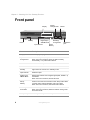
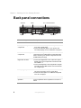
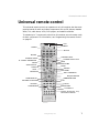
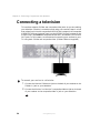
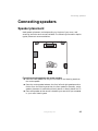
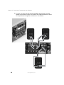
1
Your Gateway
KAS-303 Home Theater
systemguide
Setting up
Troubleshooting
Contents
1 Checking Out Your Gateway Receiver . . . . . . . . . . . . . . . . . . . . . . . . . . . 1
Features . . . . . . . . . . . . . . . . . . . . . . . . . . . . . . . . . . . . . . . . . . . . . . . . . . . . . . . . . . . 2
Important Safeguards . . . . . . . . . . . . . . . . . . . . . . . . . . . . . . . . . . . . . . . . . . . . . . . . 2
Package contents . . . . . . . . . . . . . . . . . . . . . . . . . . . . . . . . . . . . . . . . . . . . . . . . . . . 3
Front panel . . . . . . . . . . . . . . . . . . . . . . . . . . . . . . . . . . . . . . . . . . . . . . . . . . . . . . . . 4
Display . . . . . . . . . . . . . . . . . . . . . . . . . . . . . . . . . . . . . . . . . . . . . . . . . . . . . . . . . 5
Back panel connections . . . . . . . . . . . . . . . . . . . . . . . . . . . . . . . . . . . . . . . . . . . . . . 6
Universal remote control . . . . . . . . . . . . . . . . . . . . . . . . . . . . . . . . . . . . . . . . . . . . . . 7
Inserting batteries . . . . . . . . . . . . . . . . . . . . . . . . . . . . . . . . . . . . . . . . . . . . . . . 11
2 Connecting Components and Speakers . . . . . . . . . . . . . . . . . . . . . . . . . 13
Understanding video connections . . . . . . . . . . . . . . . . . . . . . . . . . . . . . . . . . . . . . .
Understanding audio connections . . . . . . . . . . . . . . . . . . . . . . . . . . . . . . . . . . . . . .
Connecting the AM loop antenna . . . . . . . . . . . . . . . . . . . . . . . . . . . . . . . . . . . . . .
Connecting the FM antenna . . . . . . . . . . . . . . . . . . . . . . . . . . . . . . . . . . . . . . . . . .
Connecting a DVD player . . . . . . . . . . . . . . . . . . . . . . . . . . . . . . . . . . . . . . . . . . . .
Connecting a 6 or 7 channel component . . . . . . . . . . . . . . . . . . . . . . . . . . . . . . . .
Connecting a VCR . . . . . . . . . . . . . . . . . . . . . . . . . . . . . . . . . . . . . . . . . . . . . . . . . .
Connecting a tape component . . . . . . . . . . . . . . . . . . . . . . . . . . . . . . . . . . . . . . . .
Connecting an AUX component . . . . . . . . . . . . . . . . . . . . . . . . . . . . . . . . . . . . . . .
Connecting a television . . . . . . . . . . . . . . . . . . . . . . . . . . . . . . . . . . . . . . . . . . . . . .
Connecting speakers . . . . . . . . . . . . . . . . . . . . . . . . . . . . . . . . . . . . . . . . . . . . . . . .
Speaker placement . . . . . . . . . . . . . . . . . . . . . . . . . . . . . . . . . . . . . . . . . . . . . .
Making the connections . . . . . . . . . . . . . . . . . . . . . . . . . . . . . . . . . . . . . . . . . .
Plugging in your components . . . . . . . . . . . . . . . . . . . . . . . . . . . . . . . . . . . . . . . . .
14
15
16
17
18
19
20
22
23
24
25
25
26
35
3 Using the Receiver . . . . . . . . . . . . . . . . . . . . . . . . . . . . . . . . . . . . . . . . . . . . . . 37
Turning the receiver on and off . . . . . . . . . . . . . . . . . . . . . . . . . . . . . . . . . . . . . . . .
Setting up your speakers . . . . . . . . . . . . . . . . . . . . . . . . . . . . . . . . . . . . . . . . . . . .
Adjusting the speaker settings . . . . . . . . . . . . . . . . . . . . . . . . . . . . . . . . . . . . .
Using the universal remote control . . . . . . . . . . . . . . . . . . . . . . . . . . . . . . . . . . . . .
Operating components with the universal remote control . . . . . . . . . . . . . . . .
Programming the remote control . . . . . . . . . . . . . . . . . . . . . . . . . . . . . . . . . . .
Switching between connected components . . . . . . . . . . . . . . . . . . . . . . . . . . . . . .
Surround sound . . . . . . . . . . . . . . . . . . . . . . . . . . . . . . . . . . . . . . . . . . . . . . . . . . . .
Surround modes . . . . . . . . . . . . . . . . . . . . . . . . . . . . . . . . . . . . . . . . . . . . . . . .
Selecting the surround mode . . . . . . . . . . . . . . . . . . . . . . . . . . . . . . . . . . . . . .
Adjusting the channel levels . . . . . . . . . . . . . . . . . . . . . . . . . . . . . . . . . . . . . . .
Storing channel levels in memory . . . . . . . . . . . . . . . . . . . . . . . . . . . . . . . . . .
38
39
39
42
42
43
46
47
47
50
52
53
i
Adjusting the LFE level . . . . . . . . . . . . . . . . . . . . . . . . . . . . . . . . . . . . . . . . . . .54
Adjusting the tone . . . . . . . . . . . . . . . . . . . . . . . . . . . . . . . . . . . . . . . . . . . . . . .55
Compressing the dynamic range . . . . . . . . . . . . . . . . . . . . . . . . . . . . . . . . . . . .55
Adjusting Dolby Pro Logic II Music parameters . . . . . . . . . . . . . . . . . . . . . . . .56
Listening to the radio . . . . . . . . . . . . . . . . . . . . . . . . . . . . . . . . . . . . . . . . . . . . . . . .57
Selecting the tuner . . . . . . . . . . . . . . . . . . . . . . . . . . . . . . . . . . . . . . . . . . . . . . .57
Manual tuning . . . . . . . . . . . . . . . . . . . . . . . . . . . . . . . . . . . . . . . . . . . . . . . . . . .57
Auto tuning . . . . . . . . . . . . . . . . . . . . . . . . . . . . . . . . . . . . . . . . . . . . . . . . . . . . .58
Memorizing radio stations . . . . . . . . . . . . . . . . . . . . . . . . . . . . . . . . . . . . . . . . .58
Tuning to preset stations . . . . . . . . . . . . . . . . . . . . . . . . . . . . . . . . . . . . . . . . . .59
Analog Audio/Video recording . . . . . . . . . . . . . . . . . . . . . . . . . . . . . . . . . . . . . . . . .59
Digital Audio recording with an MD recorder . . . . . . . . . . . . . . . . . . . . . . . . . . . . . .61
Using the sleep timer . . . . . . . . . . . . . . . . . . . . . . . . . . . . . . . . . . . . . . . . . . . . . . . .62
Adjusting the display brightness . . . . . . . . . . . . . . . . . . . . . . . . . . . . . . . . . . . . . . . .62
4 Using the OSD. . . . . . . . . . . . . . . . . . . . . . . . . . . . . . . . . . . . . . . . . . . . . . . . . . .63
Displaying the current status . . . . . . . . . . . . . . . . . . . . . . . . . . . . . . . . . . . . . . . . . .64
Using the Menu screen . . . . . . . . . . . . . . . . . . . . . . . . . . . . . . . . . . . . . . . . . . . . . .65
OSD menus and options . . . . . . . . . . . . . . . . . . . . . . . . . . . . . . . . . . . . . . . . . .66
5 Maintaining and Troubleshooting Your Receiver . . . . . . . . . . . . . . . .69
Cleaning and maintenance . . . . . . . . . . . . . . . . . . . . . . . . . . . . . . . . . . . . . . . . . . . .70
Troubleshooting . . . . . . . . . . . . . . . . . . . . . . . . . . . . . . . . . . . . . . . . . . . . . . . . . . . .70
Initializing the receiver . . . . . . . . . . . . . . . . . . . . . . . . . . . . . . . . . . . . . . . . . . . .72
Technical support . . . . . . . . . . . . . . . . . . . . . . . . . . . . . . . . . . . . . . . . . . . . . . . . . . .73
Telephone support . . . . . . . . . . . . . . . . . . . . . . . . . . . . . . . . . . . . . . . . . . . . . . .73
Internet . . . . . . . . . . . . . . . . . . . . . . . . . . . . . . . . . . . . . . . . . . . . . . . . . . . . . . . .73
A Specifications and Setup Codes . . . . . . . . . . . . . . . . . . . . . . . . . . . . . . . . .75
Specifications . . . . . . . . . . . . . . . . . . . . . . . . . . . . . . . . . . . . . . . . . . . . . . . . . . . . . .76
LN-520 receiver specifications . . . . . . . . . . . . . . . . . . . . . . . . . . . . . . . . . . . . . .76
KAS-303 speakers specifications . . . . . . . . . . . . . . . . . . . . . . . . . . . . . . . . . . . .78
SW303 subwoofer specifications . . . . . . . . . . . . . . . . . . . . . . . . . . . . . . . . . . . .79
Setup Codes . . . . . . . . . . . . . . . . . . . . . . . . . . . . . . . . . . . . . . . . . . . . . . . . . . . . . . .80
TV setup codes . . . . . . . . . . . . . . . . . . . . . . . . . . . . . . . . . . . . . . . . . . . . . . . . .80
VCR setup codes . . . . . . . . . . . . . . . . . . . . . . . . . . . . . . . . . . . . . . . . . . . . . . . .85
DVD setup codes . . . . . . . . . . . . . . . . . . . . . . . . . . . . . . . . . . . . . . . . . . . . . . . .91
Cable Set-top Box setup codes . . . . . . . . . . . . . . . . . . . . . . . . . . . . . . . . . . . . .92
Satellite Set-top Box setup codes . . . . . . . . . . . . . . . . . . . . . . . . . . . . . . . . . . .95
Aux-Tape/MiniDisc setup codes . . . . . . . . . . . . . . . . . . . . . . . . . . . . . . . . . . . . .96
Aux-Laserdisc setup codes . . . . . . . . . . . . . . . . . . . . . . . . . . . . . . . . . . . . . . . .96
Aux-Tape setup codes . . . . . . . . . . . . . . . . . . . . . . . . . . . . . . . . . . . . . . . . . . . .96
ii
Aux-Amplifier setup codes . . . . . . . . . . . . . . . . . . . . . . . . . . . . . . . . . . . . . . . .
Aux-Home Automation setup codes . . . . . . . . . . . . . . . . . . . . . . . . . . . . . . . . .
Aux-DBS setup codes . . . . . . . . . . . . . . . . . . . . . . . . . . . . . . . . . . . . . . . . . . . .
Aux-Accessory setup codes . . . . . . . . . . . . . . . . . . . . . . . . . . . . . . . . . . . . . . .
CD setup codes . . . . . . . . . . . . . . . . . . . . . . . . . . . . . . . . . . . . . . . . . . . . . . . .
97
98
98
99
99
B Safety, Regulatory, and Legal Information . . . . . . . . . . . . . . . . . . . . . 103
Index . . . . . . . . . . . . . . . . . . . . . . . . . . . . . . . . . . . . . . . . . . . . . . . . . . . . . . . . . . . . . . 111
iii
iv
Checking Out
Your Gateway
Receiver
1
This chapter provides basic information about your
Gateway Receiver.
Read this chapter to learn about:
■
Warnings and safeguards
■
Controls and connections
■
Remote control
1
Chapter 1: Checking Out Your Gateway Receiver
Features
A powerful, 1000-watt, 6.1 home theater system featuring TrueDigital™
amplification for premium, multichannel digital sound.
■
600-watt audio receiver
■
400-watt Hsu Research™-engineered sub-woofer
■
5 satellite and 1 Ventriloquist™ center channel speakers
■
Analog and digital audio inputs and outputs.
■
Composite and S-Video video inputs and outputs.
Important Safeguards
Warning
Risk of electric shock - Do not open
To reduce the risk of electric shock, do no remove the
cover. There are no user-serviceable parts inside.
Removing the cover voids the warranty.
Have your receiver repaired by qualified service personnel
only.
Warnings and precautions
2
■
Disconnect all cables before moving your receiver. Moving your receiver
with its cables attached may damage the cables and cause fire or electric
shock danger.
■
Do not expose your receiver to rain or moisture.
■
Keep your receiver away from excessive dust, high temperatures, moisture,
or direct sunlight.
■
Use your receiver in a well-ventilated area and do not cover the ventilation
openings.
■
Do not modify your receiver or use an unshielded power cord or video
output source cable, or you may experience excessive interference.
www.gateway.com
Package contents
■
Disconnect your receiver and unplug the power cord when not used for
a long period of time.
■
For more safety information, see “Important safety information” on
page 103.
Package contents
Along with your receiver, the packaging box contains the following items:
■
Remote control
■
Two AAA batteries
■
RCA audio/video cables
■
AM Loop antenna
■
FM antenna
■
User guide
You can purchase these optional accessories for your receiver:
■
S-Video cable
■
AC-3 (Toslink) cable
www.gateway.com
3
Chapter 1: Checking Out Your Gateway Receiver
Front panel
Adjust/
Tuning/Preset
Display
Standby
Input Selector
4
Decoding/
Tuning Mode
Digital Input/
AM/FM Mode
Power
Volume
Setup/
Memory
Headphone
jack
Item
Description
Display
See “Display” on page 5.
Adjust/
Tuning/Preset
When in Setup mode, adjusts submenu items.
When the tuner is selected, tunes the radio manually,
automatically, or to preset radio stations.
Volume
Turns the volume up or down.
Power
Turns the receiver on and off.
Standby
Lights when the receiver is in Standby mode.
Input Selector
Switches inputs.
Digital Input/
AM/FM Mode
Digital Input selector when a digital signal (AUX, VIDEO 1-3)
is selected.
When the tuner is selected, selects the band.
Setup/
Memory
Press for more than two seconds to enter Setup mode. While
in Setup mode, switches between main menu items.
When the tuner is selected, memorizes radio stations.
Decoding/
Tune Mode
When in Setup mode, switches submenu items.
When the tuner is selected, switches between Tuning mode
and Preset mode.
Headphone jack
Connect your headphones to this jack.
www.gateway.com
Front panel
Display
Direct indicator
Stereo indicator
Tuned indicator
Main display
ST TUNED TIMER R2 DIRECT
Memory indicator
TAPE 2M PRESET
MEM 1
dB
kHz
MHz
DTS ES
DIGITAL-EX
ft
PROLOGIC II CM DSP AUTO DIGITAL SLEEP
Auto mode indicator
Surround mode indicators
Preset/Sleep/Distance
indicators
Digital input signal indicator
Item
Description
Main display
Displays items such as, Input source, frequency,
volume level, and operating information.
STEREO indicator
Displays stereo radio signal status.
TUNED indicator
Displays tuned radio station status.
DIRECT indicator
Displays direct mode status.
MEMory indicator
Displays the selected memory channel.
Surround mode indicators
Displays the currently selected surround sound
mode.
AUTO indicator
Displays automatic mode status.
DIGITAL input signal indicator
Displays presence of a digital audio signal.
PRESET number, SLEEP time,
Speaker distance display
Displays presets, sleep timer, and speaker
distance information.
www.gateway.com
5
Chapter 1: Checking Out Your Gateway Receiver
Back panel connections
Antenna
Video
Digital
Audio
Subwoofer
Connector Array
Description
Antenna
Connect AM and FM antennas.
Video (and audio)
components
■
■
Speakers
Connect the VIDEO 1-3 jacks to components, such
as a VCR or DVD player.
Connect the Monitor jacks to your primary and
secondary displays, such as a television or projector.
6 or 7 channel direct input
components
Connect the analog audio outputs of a 6 or 7 channel
component such as a DVD player or external decoder.
When connecting a 6 channel component leave the
SURR BACK jack empty.
Digital INs and OUT
■
■
Audio (only) components
■
■
6
6 or 7 channel direct
Connect the Digital INs to the coaxial and optical
Digital OUTs of the components connected to AUX
and VIDEO 1-3.
Connect the Digital OUT to the Digital IN of a digital
recorder such as an MD recorder or CD recorder that
has a digital input.
Connect the TAPE IN/OUT jacks to an audio
only-type component, such as a tape deck.
Connect the AUX jacks to an additional component
such as a CD player.
Subwoofer
Connect a powered subwoofer.
Speakers
Connect speakers with an impedance of 6 ohms or
above.
www.gateway.com
Universal remote control
Universal remote control
This universal remote control can operate not only this receiver, but also most
popular brands of audio and video components such as CD players, cassette
decks, TVs, cable boxes, VCRs, DVD players, and satellite receivers.
To operate up to 7 components, other than this receiver, enter the setup code
for each component. For information, see “Programming the remote control”
on page 43.
LED
STANDBY
POWER
DEVICE
MACRO
CHANNEL/LEVEL
CHANNEL SELECT/T/V
MUTE
VOLUME
SPEAKER SETUP
PL II MUSIC PARAMETER
ADJUST
AUDIO SELECT
SUBTITLE
AUTO
ZOOM
STEREO
DSP MODE
OSD/SETUP
TEST TONE/MENU
Navigation/ENTER
DIMMER/RETURN
SLEEP/DISPLAY
REVERSE PLAY/PAUSE
PLAY
P.SCAN
RECORD
TUNE/SEARCH
PRESET/SKIP
7 CH DIRECT
Numeric keypad (0-9, 10+)/
Direct INPUT selector
www.gateway.com
7
Chapter 1: Checking Out Your Gateway Receiver
Button
POWER
Description
Power On. Turns the receiver off or puts the receiver in Standby mode. For more
information, see “Turning the receiver on and off” on page 38.
LED. Provides visual feedback when performing functions or programming
operations.
STANDBY
Standby. Turns the receiver on or puts the receiver in Standby mode. For more
information, see “Turning the receiver on and off” on page 38.
Device. Press to put the remote into a specific device mode for operating
connected components. For more information, see “Operating components with
the universal remote control” on page 42.
CH/LEVEL
CH/LEVEL
CH SEL
T/V
Channel level. Adjusts a program (television) channel or the test tone channel
levels up or down. For more information, see “Adjusting the channel levels” on
page 52.
Channel select. Selects a specific channel to adjust individual test tone channel
levels up or down. For more information, see “Adjusting the channel levels” on
page 52.
T/V. Changes inputs for connected components such as a TV or VCR.
MUTE
Mute. Mutes the sound.
Volume. Adjusts the overall volume.
VOLUME
VOLUME
ZOOM
STEREO
DSP
T. TONE
MENU
Zoom. Enlarges a part of the DVD screen.
Stereo. Turns off surround mode and puts the receiver into stereo mode. For
more information, see “Selecting the surround mode” on page 50.
DSP Mode. Cycles through the available surround modes. For more
information, see “Selecting the surround mode” on page 50.
Test tone. Enters the test tone mode. For more information, see “Adjusting the
channel levels” on page 52.
Menu. Opens the menu for connected components such as a DVD player.
, , , . Navigates the on-screen display (OSD) menus. For more
information, see “Using the OSD” on page 63.
8
www.gateway.com
Universal remote control
Button
ENTER
DIMMER
RETURN
Description
Enter. Confirms a selection in a menu. For more information, see “Using the
OSD” on page 63.
Dimmer. Adjusts the display brightness. For more information, see “Adjusting
the display brightness” on page 62.
Return. Returns from an OSD settings screen to the Setup Menu. For more
information, see “Using the OSD” on page 63.
Play (
P.SCAN
P.Scan. Scans the preset radio stations pausing at each one for 5 seconds.
For more information, see “Listening to the radio” on page 57.
Stop (
- PRESET +
). Plays the DVD, CD, or MP3.
). Stops playing the disc.
Preset/Skip back ( ). Changes the radio station to the next memorized station
or performs backward skip functions such as skipping back one CD track or DVD
chapter. For more information, see “Listening to the radio” on page 57.
Preset/Skip ahead ( ). Changes the radio station to the previous memorized
station or performs forward skip functions such as skipping ahead one CD track
or DVD chapter. For more information, see “Listening to the radio” on page 57.
7CH DIR.
7 Channel Direct. Selects audio signal from a connected 6 or 7 channel direct
input component. For more information, see “Switching between connected
components” on page 46.
Numeric keypad (0-9, 10+). Enters numbers when selecting or programming.
Direct INPUT selector. Selects corresponding connected component as source
for audio/video input. For more information, see “Switching between connected
components” on page 46.
- TUNE +
Tune/Search back ( ). Tunes in a radio station or performs backward search
functions, such as playing a CD backward quickly or playing a DVD backward
in slow motion. For more information, see “Listening to the radio” on page 57.
Tune/Search ahead( ). Tunes in a radio station or performs forward search
functions, such as playing a CD forward quickly or playing a DVD forward in
slow motion. For more information, see “Listening to the radio” on page 57.
Record. Starts recording on components, such as a VCR.
Reverse play. Reverses play for connected components, such as AUX.
Pause (
). Pauses play.
www.gateway.com
9
Chapter 1: Checking Out Your Gateway Receiver
Button
SLEEP
DISPLAY
Description
Sleep. Sets the receiver to automatically turn off after a set period of time.
Shows the on-screen display. For more information, see “Using the sleep timer”
on page 62.
Display. Turns on the display for connected components, such as a DVD player.
OSD
OSD. Opens the on-screen display (OSD) menus. For more information, see
“Using the OSD” on page 63.
SETUP
Setup. Opens the setup menu for connected components, such as a DVD
player.
AUTO
Auto. Automactially selects surround mode based on the type of digital input
signal detected. For more information, see “Surround sound” on page 47.
SUBTITLE
Subtitle. Opens the Subtitle menu.
AUDIO SEL
Audio select. Changes audio track selection for connected components, such
as a DVD player.
PLII PARA
PL II Music Parameter. Adjusts Dolby Pro Logic II music parameters. For more
information, see “Adjusting Dolby Pro Logic II Music parameters” on page 56.
SPK SET
-ADJUST-
AUTO
10
Speaker setup. Adjusts speaker settings. For more information, see “Setting
up your speakers” on page 39.
Adjust. Use to adjust above two settings.
Macro. Program macros to send many button presses with the touch of just
one button. For more information, see “Programming the remote control” on
page 43.
www.gateway.com
Universal remote control
Inserting batteries
To install the batteries:
■
Insert two AAA batteries into the remote control. Make sure that you match
the + and – on the batteries with the + and – symbols inside the battery
compartment.
Warning
Do not use rechargeable Ni-Cd batteries in this remote
control.
www.gateway.com
11
Chapter 1: Checking Out Your Gateway Receiver
12
www.gateway.com
Connecting
Components and
Speakers
2
Read this chapter to learn how to connect your receiver to
audio/video (A/V) components and speakers.
Important
Do not plug the power cord into a wall outlet
or turn the receiver on until all connections
have been made.
13
Chapter 2: Connecting Components and Speakers
Understanding video connections
Your receiver has two types of standard video connections. You should use the
best connection available to get the best display. For example, if your VCR
supports an S-video connection, connect the VCR to your receiver using S-video
instead of composite video.
Connection
Quality
Cable and Connector
Description
Good
Composite. The video signal is carried
through a single “pin.” This connection
method is the one that is most commonly
found on devices.
Better
S-Video. The video signal is split into two
signals, black-and-white and color. Text
displayed on-screen through this
connection will be noticeably sharper then
composite.
14
www.gateway.com
Understanding audio connections
Understanding audio connections
Your receiver has three types of standard audio connections. You should use
the best connection available to get the best sound. For example, if your DVD
player supports a digital audio connection, connect the DVD player to your
receiver using digital audio instead of analog stereo audio.
Connection
Quality
Cable and Connector
Good
Description
RCA Analog Stereo
The audio signal is carried through two
cables, one for the right speaker and one for
the left. This connection method is the one
that is most commonly found on devices.
Best
Use digital audio for the best sound quality.
Your receiver supports the following digital
audio connections.
Coaxial Digital
Coaxial cables are commonly used with
digital audio signals.
AC-3 (Toslink) Digital
-OR-
Toslink is a connector format for fiber optic
digital audio cables. A fiber optic digital
audio cable carries audio data in the form of
light impulses instead of electrical signals.
The Toslink connector is a square plug.
www.gateway.com
15
Chapter 2: Connecting Components and Speakers
Connecting the AM loop antenna
Place the AM loop antenna as far as possible from the receiver, TV, speaker
cables, and the power cord for best reception. The antenna is directional so set
it to a direction for the best reception.
To connect the AM loop antenna:
16
1
Unfold the AM loop antenna and snap the loop into the base.
2
Connect the antenna leads to the GND and AM clips on your receiver.
www.gateway.com
Connecting the FM antenna
Connecting the FM antenna
Change the position of the FM antenna until you get the best reception of your
favorite FM stations.
To connect the FM antenna:
1
Connect the FM antenna to the FM antenna connector on your receiver.
You may improve FM reception by using an outdoor antenna.
www.gateway.com
17
Chapter 2: Connecting Components and Speakers
Connecting a DVD player
or
To connect a DVD player to your receiver:
1
Connect the S-Video jack on the back of your DVD player to the S-Video
jack on your receiver.
2
Connect the AC-3 toslink digital audio jack on the back of your DVD player
to the AC-3 toslink digital audio in jack on your receiver.
-ORConnect the coaxial out jack on the back of your DVD player to the coaxial
in jack on your receiver.
18
www.gateway.com
Connecting a 6 or 7 channel component
Connecting a 6 or 7 channel
component
Use the 7CH DIRECT INPUT connectors on the receiver to connect the
corresponding analog outputs of a DVD player or external decoder that has 6
or 7 channel outputs.
If you are connecting a 6 channel output component, leave the surround back
(SURR BACK) connector on the receiver unused.
To connect a 6 or 7 channel component:
1
Connect the analog outputs of your 6 or 7 channel component to the
corresponding 7 channel direct input jacks on your receiver.
2
Connect the S-video jack of your 6 or 7 channel component to the S-video
jack on your receiver.
www.gateway.com
19
Chapter 2: Connecting Components and Speakers
Connecting a VCR
This receiver supports S-Video and composite video jacks.
To connect a VCR using S-Video:
•
20
1
Connect the red (R) and white (L) audio out jacks on the back of your VCR
to the R and L audio in jacks on your receiver.
2
Connect the red (R) and white (L) audio in jacks on the back of your VCR
to the R and L audio out jacks on your receiver.
3
Connect the S-video out jack on the back of your VCR to the S-video in
jack on your receiver.
4
Connect the S-video in jack on the back of your VCR to the S-video out
jack on your receiver.
www.gateway.com
Connecting a VCR
To connect a VCR using composite video:
•
1
Connect the red (R) and white (L) audio out jacks on the back of your VCR
to the R and L audio in jacks on your receiver.
2
Connect the red (R) and white (L) audio in jacks on the back of your VCR
to the R and L audio out jacks on your receiver.
3
Connect the composite video out jack on the back of your VCR to the
composite video in jack on your receiver.
4
Connect the composite video in jack on the back of your VCR to the
composite video out jack on your receiver.
www.gateway.com
21
Chapter 2: Connecting Components and Speakers
Connecting a tape component
To connect a tape component:
22
1
Connect the red (R) and white (L) audio out jacks on the back of your tape
component to the R and L audio in jacks on your receiver.
2
Connect the red (R) and white (L) audio in jacks on the back of your tape
component to the R and L audio out jacks on your receiver.
www.gateway.com
Connecting an AUX component
Connecting an AUX component
The AUX jacks may be connected to an additional audio component such as
a CD player, tape deck, or game console.
To connect an AUX component:
1
Connect the red (R) and white (L) audio out jacks on the back of your AUX
component to the R and L audio in jacks on your receiver.
www.gateway.com
23
Chapter 2: Connecting Components and Speakers
Connecting a television
This receiver supports S-Video and composite video jacks. As you are making
your television (monitor) connections and using your receiver, keep in mind
that a signal input into the composite VIDEO IN jack is output to the composite
VIDEO OUT jacks and a signal input into the S-VIDEO IN jack is output to the
S-VIDEO OUT jacks and the composite MONITOR 1 and MONITOR 2 VIDEO
OUT jacks. For this reason, we recommend connecting your receiver to your
TV using both S-Video and composite video. (S-Video cable not supplied)
To connect your receiver to a television:
24
1
Connect the Monitor S-Video out jack on the back of your receiver to the
S-Video in jack on your television.
2
Connect the Monitor 1 or Monitor 2 composite video out jack on the back
of your receiver to the composite video in jack on your television.
www.gateway.com
Connecting speakers
Connecting speakers
Speaker placement
Ideal speaker placement varies depending on the size of your room, wall
coverings, and other environment variables. The following information depicts
typical placement recommendations.
Front left and right speakers and center speaker
■
Place the front speakers so they are no closer to the listening area than
the center speaker.
■
Place the center speaker between the front left and right speakers and no
further from the listening area than the front speakers. Generally, center
speaker placement is made either directly above or directly below the TV.
■
Place each speaker so that sound is aimed at your ears while you are seated
in your main listening area.
www.gateway.com
25
Chapter 2: Connecting Components and Speakers
Surround left and right speakers
■
Place the surround speakers approximately 40 inches (1 meter) above the
ear level of a seated listener on the direct left and right or slightly behind
the listener.
Surround back speaker
■
Place the surround back speaker at the rear center of your listening area
facing toward the listening area at a slightly higher position
(0 to 10 inches) than the surround speakers.
■
We recommend installing the surround back speaker at a slightly
downward facing angle. This helps prevent the surround back channel
signals from reflecting off the TV or screen at the front center.
Subwoofer
■
The powerful deep bass sounds produced by the subwoofer are
non-directional, meaning you cannot tell where the sound is coming from.
Place the subwoofer anywhere in your room. The closer to a wall or corner
that you place your subwoofer the bassier the sound becomes.
Making the connections
Connect speakers firmly and correctly according to their channel (left and right)
and their polarity (+ and –). If the connections are faulty, the speakers will not
reproduce sound. If the polarity of the connections are incorrect, the sound
will be unnatural and lack bass.
Warning
Use speakers with an impedance of 6 ohms or above.
Do not let the bare speaker wires touch each other or any
metal part of this receiver. This could damage the receiver
and/or the speakers.
26
www.gateway.com
Connecting speakers
To connect speakers to your receiver:
1
Connect the striped-edge speaker cable to the red (positive) speaker cable
connector. Connect the non-striped edge speaker cable to the black
(negative) speaker cable connector.
Important
Make sure that you clamp down on the bare speaker wire
and not on the insulation.
www.gateway.com
27
Chapter 2: Connecting Components and Speakers
2
28
Connect the right and left surround speakers and the back surround
speaker to the receiver. Match the positive and negative cables from Step 1
to the positive and negative connectors on the receiver.
www.gateway.com
Connecting speakers
3
Connect the center speaker to the receiver, making sure to match the
positive and negative connectors.
www.gateway.com
29
Chapter 2: Connecting Components and Speakers
4
30
Connect the left and right front speakers to the center speaker, making
sure to match the positive and negative connectors.
www.gateway.com
Connecting speakers
5
Turn the center speaker’s Ventriloquist Function to ON.
www.gateway.com
31
Chapter 2: Connecting Components and Speakers
6
32
Connect the subwoofer to the receiver.
www.gateway.com
Connecting speakers
7
Plug in the subwoofer.
www.gateway.com
33
Chapter 2: Connecting Components and Speakers
8
Switch the subwoofer to Digital Receiver, turn the Volume to ~5, then flip
the POWER switch to ON.
Certain settings need to be made to your receiver to match your KAS-303
speakers. See “Setting up your speakers” on page 39 for more information
on setting up and configuring your speakers.
34
www.gateway.com
Plugging in your components
Plugging in your components
After you have made all the connections, plug in your receiver and your
connected components.
www.gateway.com
35
Chapter 2: Connecting Components and Speakers
36
www.gateway.com
Using the
Receiver
3
Read this chapter to learn how to:
■
Turn the receiver on and off
■
Set up the speakers
■
Use the universal remote control
■
Listen to a program source
■
Understand surround sound
■
Listen to the radio
■
Record analog audio and video
■
Record digital audio
■
Use the sleep timer
■
Adjust the display brightness
37
Chapter 3: Using the Receiver
Turning the receiver on and off
To turn the receiver on:
1
Press the power button on the receiver. The receiver enters Standby mode.
Each subsequent press of the power button on the receiver switches the
receiver between Standby mode and off.
2
Press the power button
on the remote control. The receiver turns on.
Each subsequent press of the power button on the remote control switches
the receiver between Standby mode and on.
POWER
To turn the receiver off:
■
38
Press the power button on the receiver. The receiver turns off.
www.gateway.com
Setting up your speakers
Setting up your speakers
Adjusting the speaker settings
After you have installed your receiver and connected all the components, you
should adjust the speaker settings for the optimum sound acoustics for your
environment and speaker layout.
Setting the type of speakers
The composition and frequency response of the signals from the surround
channels adjust automatically according to the combination of speaker types
in use.
Select Large or Small not according to the actual size of the speaker but according
to the speaker’s capacity for playing low frequency signals.
Crossover Frequency is the frequency (Hz) below which the bass sound of each
main speakers is instead sent to the subwoofer or, when not using a subwoofer,
speakers set to Large.
Large — Select this when connecting speakers that can fully reproduce sounds
below the Crossover Frequency of your speakers.
Small — Select this when connecting speakers that cannot fully reproduce
sound below the Crossover Frequency. When this setting is selected, sound
below the Crossover Frequency is assigned to the subwoofer or, when not using
a subwoofer, speakers set to Large.
None — Select this when no surround speakers are connected. When this
setting is selected, the surround sound signals are sent to the front speakers.
www.gateway.com
39
Chapter 3: Using the Receiver
Yes / None — Select Yes if a subwoofer is connected. Select None if a subwoofer
is not connected.
40
■
See the specifications of the speakers that you are connecting. For example,
if the frequency range of your speakers is 80 Hz ~ 12 KHz, then the
Crossover Frequency is 80 Hz.
■
If you do not know the specifications for your speakers, try comparing the
sound at both settings (set the volume to a low level so you do not damage
the speakers) to determine the correct setting.
■
Depending on how you set your speakers, not all options may be available
to you. For example, if you set your Front L/R speakers to Large, you will
have Large, Small, and None as options for your Center speaker. But if you
set your Front L/R speakers to Small, the only options available for your
Center speaker will be Small and None.
www.gateway.com
Setting up your speakers
Speaker distance settings
When using 5.1 channel surround playback with Dolby Digital or DTS sources,
the center and surround speakers should be the same distance from the main
listening position as the front speakers. By specifying the distance between the
listening position and each speaker, the center and surround speaker’s delay
times automatically adjust to create the ideal listening environment.
To adjust the speaker settings:
SPK SET
1
Press the Speaker Setup button
on the remote control to cycle
between the available Speaker Setting Modes.
2
When the Speaker Setting Mode you want to adjust is selected, press the
-ADJUST-
Adjust Up or Adjust Down
change the speaker setting.
Displayed symbol
■
buttons on the remote control to
Corresponding setting
F
Front
C
Center
S
Surround
L
Large
S
Small
N
None
When adjusting the Crossover Frequency setting for your subwoofer, the
available options are 80 Hz, 120 Hz, 160 Hz, and 200 Hz. Your KAS-303
Home Theater satellite speakers have a range of 150 Hz ~ 18.5 KHz, so set
the subwoofer Crossover Frequency to 160 Hz.
You can also adjust speaker settings using your remote control and the OSD.
For more information, see “OSD menus and options” on page 66.
You can also adjust speaker settings using the SETUP button on the receiver
www.gateway.com
41
Chapter 3: Using the Receiver
Using the universal remote control
Operating components with the universal
remote control
To operate components with the universal remote control:
42
1
Enter the Setup code for each component, other than this receiver, that
you want to control. For more information, see “Programming the remote
control” on page 43.
2
3
Turn on the component you want to operate.
Press the DEVICE button on the remote control that corresponds to the
component you want to operate.
www.gateway.com
Using the universal remote control
4
Aim the remote control at the remote sensor of the component that you
want to operate and press the button that corresponds to the function you
want to perform.
60o
7m
Programming the remote control
This remote control can control up to 8 different components.
Before operating audio and video components, other than this receiver, use this
remote control to enter the setup code for each component.
By factory default, 000 is stored in the memory for the CD, DVD, and AUX
device buttons. You do not need to enter a code unless the default code of 000
does not work.
www.gateway.com
43
Chapter 3: Using the Receiver
Entering a setup code
To enter a setup code:
1
2
Turn on the component you want to control.
3
While pressing and holding down the ENTER button on the remote
control, press the DEVICE button on the remote control for the
corresponding component for more than 1 second. The LED flickers once.
Locate the setup code for your connected component. See “Setup Codes”
on page 80.
The AUDIO DEVICE button is reserved for the receiver and cannot be
programmed for other components.
4
While aiming the remote control at the remote sensor on your connected
component, enter the 3-digit code that you located in Step 2.
If you entered the code correctly, the LED flickers twice. Test the code by
pressing the POWER (or STANDBY) button on the remote control. If your
component does not turn off, repeat the procedure using each code listed
for your component’s manufacturer until you find a code that works.
If the LED did not flicker twice, repeat the above procedure and try entering
the same code again.
Manufacturers may use different setup codes for the same product category.
Check to see if the code you have entered operates as many controls as possible.
If only a few functions operate, check to see if another code operates more
buttons.
Programming a macro function
Using the macro function, you can program up to 10 remote control button
presses into a single button. The universal remote control has 3 macro buttons,
M1, M2, and M3.
44
www.gateway.com
Using the universal remote control
To program a macro:
1
Press and hold down both the ENTER button on the remote control and
the macro button you want to program (M1, M2, or M3). The LED flickers
once.
2
First press the DEVICE button for the device that you want to control with
this macro, then press the operation buttons you want to program in the
order that you want them to execute.
3
Press the ENTER button on the remote control. If the macro was
programmed successfully, the LED flickers twice.
Remove a macro by following the above procedure except skip Step 2.
Change a macro by programming a new macro into the macro button. The new
macro automatically overwrites the old macro.
Using a macro function
To use a macro:
■
Aim the remote control at the remote control sensor of the component
that you want to operate, then press the macro button for the macro you
want to run.
The macro function of this remote control may not work with all components.
For example, the codes programmed into a MACRO button transmit at
0.5 second intervals. If the component cannot complete an operation within
0.5 seconds, it may miss the next code. In this example, you would not be able
to use that particular macro with the component.
www.gateway.com
45
Chapter 3: Using the Receiver
Switching between connected
components
To switch between connected components:
1
Press the Input Selector button on the receiver or press one of the Direct
Input Selector buttons on the remote control.
■
2
If you selected Aux, Video 1, Video 2, or Video 3, press the Digital Input
button on the receiver to select the corresponding digital or analog input.
■
3
4
5
46
The available input source changes are: Tuner, Tape, Aux, Video 1,
Video 2, Video 3, and 7-Direct.
The available digital or analog inputs are: A(nalog), o(ptical) 1,
o(ptical) 2, and c(oaxial) 1
Press the Decoding button on the receiver or the Auto button on the remote
control to select the decoding mode you want.
■
The available decoding modes are: In-Auto, In-DTS, and In-PCM.
■
You cannot select a decoding mode unless you have also selected a
digital input source.
■
Noise may be generated at the beginning of playback and while
searching when you are in In-Auto decoding mode during DTS
playback. If this happens, switch to In-DTS mode.
Use the component you selected for playback.
Press the up and down Volume buttons on the receiver or on the remote
control to adjust the volume.
www.gateway.com
Surround sound
6
If you want to mute the sound, press the MUTE button on the remote
control.
7
If you want to listen with headphones, connect headphones to the Phones
jack on the receiver. Sound to the speakers is automatically turned off and
any multi-channel sound is automatically downmixed to a 2-channel
(2-CH DOWNMIX) downmix mode.
You can also select the digital signal input using your remote control and the
OSD. For more information, see “Using the OSD” on page 63.
Surround sound
This receiver incorporates a sophisticated Digital Signal Processor that lets you
create optimum sound quality and sound atmosphere in your personal Home
Theater.
Surround modes
Your receiver supports multichannel surround modes and 2-channel surround
modes.
Multichannel surround modes
Mode
Description
DTS™ Digital
Surround
DTS Digital Surround (DTS) is a multichannel digital signal format which
handles higher data rates than Dolby Digital.
DTS - ES Extended
Surround™
This is a new multichannel digital signal format which greatly improves the
360-degree surround impression and space expression. In addition to the
5.1 channels, DTS-ES Extended Surround also offers the surround back
(sometimes also referred to as surround center) channel for surround
playback with a total of 6.1 channels. DTS-ES Extended Surround includes
the DTS-ES™ Discrete 6.1 and DTS-ES™ Matrix 6.1 signal formats.
DTS Neo: 6™
surround
This mode applies conventional two-channel signals such as digital PCM
or analog stereo signals to the high precision digital matrix decoder used
for DTS-ES Matrix 6.1 to achieve 6.1-channel surround playback. DTS Neo
: 6 includes DTS Neo: 6 Cinema and DTS Neo: 6 Music signal formats.
www.gateway.com
47
Chapter 3: Using the Receiver
Mode
Description
Dolby Digital™
Dolby Digital discs support recordings of up to 5.1 channels of digital signals,
which reproduce much better sound quality, spatial expansion, and dynamic
range characteristics than the previous Dolby Surround effects.
Dolby Digital EX™
This mode uses a matrix decoder to create the back (sometimes referred
to as surround center) signal from the surround left and right signals in a
Dolby Digital 5.1 channel source and provides 6.1 channel surround
playback. For the best results, this mode should be selected during playback
of sources recorded in Dolby Digital Surround EX.
When Dolby Digital EX sources are decoded with a Dolby Digital EX
decoder, the format is automatically detected and Dolby Digital EX mode
is selected. However, some Dolby Digital EX sources may be detected as
Dolby Digital sources. In this case, the Dolby Digital EX mode should be
selected manually.
Dolby Pro Logic™
Dolby Pro Logic is a specially encoded two-channel surround format which
consists of four channels (front left, center, front right, and surround). The
surround channel is monaural and is played through both surround
speakers.
Dolby Pro Logic II™
surround
This mode applies conventional two-channel signals such as digital PCM
or analog stereo signals as well as Dolby Surround signals to surround
processing. Dolby Pro Logic II surround includes Dolby Pro Logic II Cinema,
Dolby Pro Logic II Music, and Dolby Virtual signal formats.
MPEG™
Multichannel
Though the number of audio channels is 5.1 (which is the same as Dolby
Digital), MPEG Multichannel discs are much better at matching individual
sounds to the correct position in the sound stage. MPEG Multichannel works
well when using the 7 CH DIRECT INPUTs to playback the sound from an
additional multichannel decoder. For details, see to the user’s guide for your
connected 7-channel component.
48
www.gateway.com
Surround sound
2-channel surround modes
The following modes apply conventional 2-channel signals such as digital PCM
or analog stereo signals to high performance Digital Signal Processor to recreate
sound fields artificially. Select from one of the following 2-channel surround
modes:
Mode
Description
Theater
This mode provides the effect of being in a theater -in-the round while watching a play.
Movie
This mode provides the effect of being in a movie theater while watching a movie.
Hall 1/2
This mode provides the ambience of a chamber hall for chamber music or an
instrumental solo (Hall 1) or a concert hall for orchestral music or an opera (Hall 2).
Stadium
This mode provides the expansive sound field to achieve the true stadium effect of
watching sporting events, such as football.
Church
This mode provides the ambience of a church for baroque, string orchestral, or choral
group music.
Club 1/2
This mode creates the sound field of a jazz club with a low ceiling and hard walls
(Club 1) or a live club with a relatively spacious floor (Club 2).
Arena 1/2
This mode provides the feeling of a live concert in a medium-sized (Arena 1) or large
(Arena 2) arena.
Game
Use this mode for video game sources.
Matrix
This mode reproduces delayed signals from the surround channels emphasizing the
sense of expansion for music sources.
www.gateway.com
49
Chapter 3: Using the Receiver
For your reference, the sound from each channel can be reproduced according
to the surround modes as follows:
Modes
Channels
Front
L/R
Center
Surround
L/R
Surround
Back
Subwoofer
DTS
×
×
×
DTS ES DISCRETE/MATRIX
×
×
×
×
×
DTS NEO CINEMA/MUSIC
×
×
×
×
×
DOLBY DIGITAL
×
×
×
DOLBY DIGITAL EX
×
×
×
DOLBY PRO LOGIC
×
×
×
×
DOLBY PRO LOGIC II CINEMA/MUSIC
×
×
×
×
DOLBY VIRTUAL
×
MPEG
×
×
×
×
MATRIX
×
×
×
×
Other Surround
×
×
×
×
STEREO
×
7 CH DIRECT
×
×
×
×
×
×
×
×
×
×
×
Selecting the surround mode
To select the surround mode:
■
50
Press the left and right DSP mode buttons on the remote control to cycle
through the surround modes.
www.gateway.com
Surround sound
The signal format of your selected input source determines the available
surround modes.
Signal format of input source
Selected decoding mode
Selectable surround mode *
Dolby Digital 5.1,
Dolby Digital EX 6.1 channel sources
IN-AUTO mode
(DOLBY DIGITAL EX),
DOLBY DIGITAL,
DOLBY VIRTUAL
Dolby Digital 2-channel
IN-AUTO mode
(DOLBY DIGITAL EX),
PL II CINEMA, PL II MUSIC,
PRO LOGIC, DOLBY VIRTUAL
PCM (2 channel) sources
IN-AUTO, IN-PCM mode
PL II CINEMA, PL II MUSIC,
PRO LOGIC,
DOLBY VIRTUAL,
NEO 6 CINEMA,
NEO 6 MUSIC, THEATER,
MOVIE, HALL 1/2, STADIUM,
CHURCH, CLUB 1/2,
ARENA 1/2, GAME, MATRIX
DTS sources
IN-AUTO, IN-DTS mode
corresponding DTS mode
MPEG sources
IN-AUTO mode
corresponding MPEG mode
Analog stereo sources
* Items in parenthesis are only selectable when the surround back speaker
setting is not N.
■
When 96 kHz PCM signals are input, stereo mode is selected automatically
and surround mode cannot be selected.
■
When DTS or MPEG signals are input in the IN-AUTO or IN-DTS mode,
the corresponding DTS or MPEG modes are selected regardless of DSP
MODE button actions.
■
When the selected decoding mode is not matched to the input signal
format, the DIGITAL indicator flickers and no sound is heard. Be sure to
select the required decoding mode and the available surround mode
according to the input signal format.
■
When the 7 CH DIRECT is selected as an input source, the decoding and
surround modes cannot be selected.
■
When the selected input signals are not digital signals, the surround mode
cannot be selected.
■
When using headphones, the surround mode cannot be selected.
www.gateway.com
51
Chapter 3: Using the Receiver
To select stereo mode:
■
Press the Stereo button on the remote control to cancel surround mode
and switch to stereo mode.
If Stereo mode is applied to a multi-channel DTS, Dolby Digital, or MPEG signal,
the signal is downmixed to a 2-channel downmix (2-CH DOWNMIX) mode,
allowing the multi-channel signal to be reproduced through only two speakers
or through headphones.
To cancel Stereo mode and switch back to surround mode, use the DSP Mode
buttons on your remote control.
Adjusting the channel levels
You can adjust your channel levels using test tones or manually. Ideally you
should use the test tone method first and then make any additional adjustments
through the manual process.
To adjust channel levels using test tones:
52
1
Press the T. Tone button on the remote control. The test tone plays out of
each channel in a 2-second cycle. If a speaker setting is N, the test tone
will not play out of that channel.
2
Press the CH/LEVEL up and down buttons on the remote control to adjust
the level for each channel.
3
Press the T. Tone button on the remote control to cancel the test tone.
www.gateway.com
Surround sound
To adjust channel levels manually:
1
Press the Ch. SEL button on the remote control. Each time the button is
pressed, the corresponding channel is selected and displayed for several
seconds.
■
If the receiver is set to Stereo or Dolby Virtual mode or if the speaker
setting is set to N, center, surround L/R, surround back, or the
subwoofer channel cannot be selected.
■
If the headphones are connected, you can only select the front L/R
channel.
2
Press the CH/LEVEL up and down buttons on the remote control to adjust
the level of the selected channel.
3
Repeat Step 1 and Step 2 to adjust each channel level.
Storing channel levels in memory
You can store channel level settings in memory. This lets you change the
channel levels, then recall the stored settings.
To store channel levels in memory:
1
Press the SETUP button on the receiver for more than 2 seconds to enter
Setup mode.
2
While in Setup mode, repeatedly press the SETUP button on the receiver
until P CALL appears.
3
While displaying P CALL, press the ADJUST up and down buttons on the
receiver to select P MEMORY.
4
Press the DECODING button on the receiver to confirm.
www.gateway.com
53
Chapter 3: Using the Receiver
To recall channel levels from memory:
1
Press the SETUP button on the receiver for more than 2 seconds to enter
Setup mode.
2
While in Setup mode, repeatedly press the SETUP button on the receiver
until P CALL displays.
3
While displaying P CALL, press the ADJUST up and down buttons on the
receiver to select P CALL.
4
Press the DECODING button on the receiver to confirm.
You can also work with channel levels using your remote control and the OSD.
For more information, see “OSD menus and options” on page 66.
Adjusting the LFE level
You can adjust the Low Frequency Effect (LFE) levels in Dolby Digital, DTS, and
MPEG program sources.
To adjust the LFE level:
1
Press the SETUP button on the receiver for more than 2 seconds to enter
Setup mode.
2
While in Setup mode, repeatedly press the SETUP button on the receiver
until DD L displays.
3
While displaying DD L, press the DECODING button on the receiver to cycle
between the available modes: Dolby Digital LFE (DD L), DTS LFE (DTS L),
and MPEG LFE (MP L).
4
While displaying the LFE mode you want, press the ADJUST up and down
buttons on the receiver to adjust the level.
You can also adjust the LFE level using your remote control and the OSD. For
more information, see “OSD menus and options” on page 66.
54
www.gateway.com
Surround sound
Adjusting the tone
You can adjust the tone (bass and treble).
To adjust tone:
1
Press the SETUP button on the receiver for more than 2 seconds to enter
Setup mode.
2
While in Setup mode, repeatedly press the SETUP button on the receiver
until TONE OFF or BASS appears.
3
While displaying BASS, press the DECODING button on the receiver to cycle
between the available modes: BASS, TRBL, and TONE ON.
4
While displaying the tone mode you want, press the ADJUST up and down
buttons on the receiver to adjust the tone.
You can also adjust the tone settings using your remote control and the OSD.
For more information, see “OSD menus and options” on page 66.
Compressing the dynamic range
You can adjust the compression of Dolby Digital program sources to minimize
the volume difference between high and low levels. This feature is useful if you
are listening to Dolby Digital program sources at low volume levels. This feature
can only be used for Dolby Digital program sources.
To compress the dynamic range of Dolby Digital program sources:
1
Press the SETUP button on the receiver for more than 2 seconds to enter
Setup mode.
2
While in Setup mode, repeatedly press the SETUP button on the receiver
until DYNR 0.0 appears.
www.gateway.com
55
Chapter 3: Using the Receiver
3
While displaying DYNR 0.0, press the ADJUST up and down buttons on the
receiver to cycle between the available modes: DYNR 0.0: Off, DYNR 0.5: Low
Compression, and DYNR 1.0: High Compression.
4
While displaying the tone mode you want, press the ADJUST up and down
buttons on the receiver to adjust the tone.
This function may not be available in some Dolby Digital program sources.
You can also adjust the dynamic range compression levels using your remote
control and the OSD. For more information, see “OSD menus and options” on
page 66.
Adjusting Dolby Pro Logic II Music parameters
You can adjust the surround parameters of Dolby Pro Logic II Music mode.
To adjust Dolby Pro Logic II Music parameters:
1
2
56
Press the PL II PARA. button on the remote control to select from the
following parameters:
■
Panorama mode (PANO) – Extends the front stereo image to include
the surround speakers to give a wraparound effect with side wall
imaging.
Range: OFF or ON (default is OFF)
■
Center width control (C-WID) – Adjusts the center image so it is heard
from only the center channel speaker, only from the left/right speakers
as a phantom image, or from all three front speakers.
Range: 0 to 7 (default is 0)
■
Dimension control (DIMEN) – Adjusts the sound field towards the front
or towards the rear.
Range: -4 to +2 (default is 0)
While displaying the parameter you want, press the ADJUST buttons on
the remote control to change the values.
www.gateway.com
Listening to the radio
Listening to the radio
Selecting the tuner
To select the tuner:
1
Press the INPUT SELECTOR button on the receiver or the TUNER button on
the remote control to select the tuner.
2
Press the AM/FM MODE button on the receiver to cycle between the
following bands: FM STEREO, FM MONO, and AM.
When FM stereo broadcasts are poor because of weak broadcast signals, select
the FM mono mode to reduce the noise. The FM broadcasts are reduced to
monaural sound.
Manual tuning
To manually tune the tuner:
1
If you are using the buttons on the receiver, repeatedly press the TUNE
MODE button on the receiver to select Tuning mode. The PRESET light turns
off.
- OR If you are using your remote control, go to the next step.
2
Repeatedly press the up and down TUNING/PRESET buttons on the receiver
or the – and + TUNE buttons on the remote control until the frequency you
want is set.
www.gateway.com
57
Chapter 3: Using the Receiver
Auto tuning
To automatically tune the tuner:
1
If you are using the buttons on the receiver, repeatedly press the TUNE
MODE button on the receiver to select Tuning mode. The PRESET light turns
off.
- OR If you are using your remote control, go to the next step.
2
Press the up and down TUNING/PRESET buttons on the receiver or the
– and + TUNE buttons on the remote control for more than 0.5 seconds.
The tuner searches until a station of sufficient strength is found.
Weak stations are skipped during auto tuning. To tune in a weak station, use
manual tuning.
Memorizing radio stations
You can store up to 30 radio stations in memory.
To memorize radio stations:
1
2
Tune in a station using manual or auto tuning.
3
Press the up and down TUNING/PRESET buttons on the receiver or the
– and + PRESET buttons on the remote control to select the desired preset
number (1~30) you want, then press the MEMORY button on the receiver.
Press the MEMORY button on the receiver. The MEM light flickers for
5 seconds.
You can erase a stored frequency by storing another frequency in its place.
58
www.gateway.com
Analog Audio/Video recording
Tuning to preset stations
To tune to preset stations:
1
If you are using the buttons on the receiver, repeatedly press the TUNE
MODE button on the receiver to select Preset mode. The PRESET light turns
on.
- OR If you are using your remote control, go to the next step.
2
Press the up and down TUNING/PRESET buttons on the receiver or the
– and + PRESET buttons on the remote control to select the desired preset
number (1~30).
You can scan all of the preset stations in sequence by pressing the P. SCAN
button on your remote control. The receiver pauses at each preset station for
5 seconds. When the station you want is tuned, press the button again to stop
scanning.
Analog Audio/Video recording
■
The analog signals (except front L/R channel) from the 7 CH DIRECT
inputs and the digital signals from the coaxial or optical digital inputs
cannot be recorded.
■
The volume and tone (bass and treble) settings have no effect on the
recording signals.
To record with TAPE:
1
Press the INPUT SELECTOR button on the receiver or the direct input
selector button on the remote control to select the input for your recording
source. You cannot select TAPE.
2
3
Start recording on the connected TAPE component.
Start playing on the selected input (recording source).
www.gateway.com
59
Chapter 3: Using the Receiver
To dub from video components onto VIDEO 1:
1
Press the INPUT SELECTOR button on the receiver or the VIDEO2 or VIDEO3
direct input selector button on the remote control to select VIDEO2 or
VIDEO3 as your recording source.
2
3
Start recording on the connected VIDEO 1 component.
Start playing on the VIDEO 2 or VIDEO 3 selected input (recording source).
To dub separate audio and video source signals onto VIDEO 1:
60
1
Press the INPUT SELECTOR button on the receiver or the AUX direct input
selector button on the remote control to select AUX as your audio recording
source. Make sure your audio recording source, such as a CD player, is
connected to the AUX jacks.
2
Press the OSD button on the remote control and select FUNCTION SELECT,
VIDEO SELECT, then select VIDEO 2.
3
4
Start recording on the connected VIDEO 1 component.
Start playing on the AUX and the VIDEO 2 inputs (recording source).
www.gateway.com
Digital Audio recording with an MD recorder
Digital Audio recording with an MD
recorder
.
■
You can only record digitally (without digital to analog conversion) when
the OPTICAL DIGITAL OUT jack of this receiver is connected to the
OPTICAL DIGITAL IN jack of an MD recorder or CD recorder.
■
Digital recording is available for the digital audio program sources such as
CDs, MDs, and some DVDs.
■
In most DVDs, as well as some CDs, digital recording may not be available
(depending on the signal format).
■
There are some restrictions on recording digital signals. See the operating
instructions of your digital recording equipment to see which restrictions
apply to you.
To record digital audio with an MD recorder:
1
Press the INPUT SELECTOR button on the receiver or the AUX, VIDEO1,
VIDEO2, or VIDEO3 direct input selector button on the remote control to
select AUX, VIDEO1, VIDEO2, or VIDEO3 as the input for your recording
source.
2
Press the DIGITAL INPUT button on the receiver to select the o(ptical) 1,
o(ptical) 2, or c(oaxial) 1 as your digital signal input.
3
4
Start recording on the component connected to OPTICAL DIGITAL OUT.
Start playing on the selected digital input (recording source).
You can also select the digital signal input using your remote control and the
OSD. For more information, see “Using the OSD” on page 63.
www.gateway.com
61
Chapter 3: Using the Receiver
Using the sleep timer
Use the sleep timer to automatically turn the receiver off after a specified period
of time.
.
To use the sleep timer:
■
Press the SLEEP button on the remote control to cycle between the
following sleep timer settings: 10, 20, 30, 60, 90, and OFF. The SLEEP light
turns on.
Adjusting the display brightness
You can dim or turn off the receiver’s display.
.
To adjust the display brightness:
■
Press the DIMMER button on the remote control to cycle between the
following brightness settings: ON, dimmer, and OFF.
In the OFF display mode, press any button to restore the display to ON mode.
62
www.gateway.com
Using the OSD
4
Read this chapter to learn how to adjust your receiver
settings from the on-screen display (OSD).
63
Chapter 4: Using the OSD
Displaying the current status
When the AUTO OSD is set to ON the receiver displays status information. The
information displays for several seconds then automatically turns off.
One example of displayed status information is shown below.
Displayed status information when selecting TEST TONE mode
FL
64
:---------------
----------------:
www.gateway.com
0db
Using the Menu screen
Using the Menu screen
Navigate the Menu screen using the cursor control ( ,
,
, and
),
OSD
OSD (
), and ENTER ( ENTER ) buttons on your remote control.
To adjust settings from the OSD:
1
Press the OSD button on the remote control. The Main Menu opens.
MAIN MENU
SPEAKER SETUP
FUNCTION SELECT
SURROUND MODE
SH LEVEL SETUP
AUTO OSD : ON
OSD : QUIT
, : MOVE
ENTER :
SELECT OR CHANGE
Press the OSD button on the remote control again to close the Main Menu.
2
Press the cursor up and down buttons on the remote control to select the
menu item you want.
3
4
Press Enter on the remote control to confirm your selection.
5
Follow the on-screen instructions to adjust the option.
Press the cursor up and down buttons on the remote control to select the
option you want.
www.gateway.com
65
Chapter 4: Using the OSD
OSD menus and options
Use these OSD menus and options to adjust various setting for your receiver.
Menu
Speaker Setup
OSD Display
Description
Configure Speaker settings.
Options include:
SPEAKER SETUP
SUBWOOFER
FRONT
CENTER
SURROUND
SURR. BACK
:
:
:
:
:
YES
SMALL
SMALL
SMALL
SUBWOOFER : ACTIVE
OSD : BACK
ENTER :CHANGE
,
: MOVE
1/2 PAGE
UNIT
FRONT L
FRONT R
CENTER
SURR. L
SURR. R
:
:
:
:
:
:
FEET
10ft
10ft
10ft
10ft
10ft
U.S. ANGLE : NARROW
CROSSOVER FREQ. : 80Hz
OSD : BACK
ENTER :CHANGE
,
Page 1/2
SMALL
: MOVE
2/2 PAGE
Subwoofer – Set to Yes or
No.
■ Front – Set size.
■
Center – Set size.
■
Surround – Set size.
■ Surround Back – Set size.
■
Subwoofer – Set type.
Page 2/2
■
■
■
■
■
■
■
■
■
Function Select
FUNCTION SELECT
DIGITAL INPUT
VIDEO SELECT
TONE CONTROL
DYNAMIC RANGE : 0.5
PLII (M) PARAMETER
OSD : BACK
, : MOVE
ENTER :
SELECT OR CHANGE
Configure Function settings.
Options include:
■
■
■
■
■
66
www.gateway.com
Unit – Set english or metric.
Front L – Set distance.
Front R – Set distance.
Center – Set distance.
Surround Left – Set distance.
Surround Right – Set
distance.
V.S. Angle – Set angle.
Crossover Frequency – Set
subwoofer crossover
frequency.
Digital Input – Configure
digital inputs.
Video Select – Configure
video dubbing settings.
Tone Control – Configure
tone (bass/treble) settings.
Dynamic Range – Set
dynamic range.
PLII Parameter – Adjust the
Dolby Pro Logic II Music
parameter.
Using the Menu screen
Menu
OSD Display
Surround Mode
Description
SURROUND MODE
PLII (CINEMA)
DOLBY VIRTUAL
NEO :6
SFE
DOLBY DIGITAL EX
STEREO
ENTER :
, : CHANGE
SELECT OR CHANGE
Configure the Surround mode
settings. The displayed
surround modes change
depending on the format of the
selected input signal. Options
can include:
■
■
■
■
■
■
Channel Level Setup
CH LEVEL SETUP
PRESET CALL
PRESET TRIM
CH LEVEL TRIM
LFE LEVEL TRIM
OSD : BACK
ENTER :
SELECT
Auto OSD
,
PLII
Dolby
NEO
SFE
Dolby Digital
Stereo
Configure Channel Level
settings such as Preset Trim
and Channel Level Trim. See
“Adjusting the channel levels”
on page 52.
: MOVE
MAIN MENU
SPEAKER SETUP
FUNCTION SELECT
SURROUND MODE
SH LEVEL SETUP
AUTO OSD : ON
Cycle the Auto OSD setting
between On and Off by pressing
the Enter button on the remote
control.
OSD : QUIT
, : MOVE
ENTER :
SELECT OR CHANGE
www.gateway.com
67
Chapter 4: Using the OSD
68
www.gateway.com
Maintaining and
Troubleshooting
Your Receiver
5
Read this chapter to learn how to maintain and
troubleshoot your receiver.
69
Chapter 5: Maintaining and Troubleshooting Your Receiver
Cleaning and maintenance
■
Your receiver is cooled by air circulated through the vents on the bottom
of the case. Keep these vents free of dust. With the receiver turned off and
unplugged, brush the dust away from the vents with a damp cloth. Be
careful not to drip any water into the vents. Do not attempt to clean dust
from the inside of your receiver.
■
Do not use abrasive or solvent cleaners because they can damage the finish.
■
Do not allow any excessive water or moisture to come into contact with
the surface of the receiver. If water or moisture gets inside your receiver,
operating problems and electrical and shock hazards may result.
■
Do not scratch or hit the case with your fingers or any hard objects.
Troubleshooting
As a general troubleshooting step turn you receiver off, then turn it on again.
This section provides some solutions to common problems you may experience
with your receiver.
If the problem continues, initialize your receiver by following the procedure
in “Initializing the receiver” on page 72.
No power
■
Connect the power cord securely.
■
Check the outlet using a lamp or another appliance.
Power shuts off abruptly during operation.
■
Switch off the power and check the speaker connections.
■
Adjust the speaker settings correctly.
■
Lower the volume.
No sound
70
■
Check the speaker connections.
■
Adjust the master volume.
■
Press the MUTE button to cancel the muting effect.
support..gateway.com
Troubleshooting
■
Check component connections.
■
Check the selected input source.
No sound from the surround speakers
■
Select a surround mode.
■
Adjust master volume and surround level.
■
Select the desired surround speaker setting.
■
Select a stereo or surround source.
No sound from the center speaker
■
Select the desired surround speaker setting.
■
Adjust master volume and center level.
■
Make sure center speaker setting is not set to N.
No sound from the surround back speaker
■
Under the proper situations, perform the 6.1 surround playback.
■
Adjust master volume and surround back level.
■
Select the desired surround back speaker setting.
Stations cannot be received
■
Connect an antenna.
■
Move the antenna and retry tuning.
■
Tune in the desired station frequency.
Preset stations cannot be received
■
Memorize the correct station frequency.
■
Memorize the stations again.
Poor FM reception
■
Connect an antenna.
■
Change the position of the antenna.
support..gateway.com
71
Chapter 5: Maintaining and Troubleshooting Your Receiver
Continuous hissing noise during FM reception, especially when a
stereo broadcast is received.
■
Change the position of the antenna.
■
Install an outdoor antenna.
Continuous or intermittent reception, especially at night. hissing noise
during AM
■
Keep the receiver away from noise sources such as, motors, fluorescent
lamps, and lightning.
■
Install an outdoor AM antenna.
Remote control unit does not operate.
■
Replace the batteries.
■
Remove any obstacles blocking the remote sensor.
OSD function is not available
■
Make proper video connections.
Initializing the receiver
If the display or operation of the receiver is not performing correctly, you can
initialize the receiver by performing the following procedure.
Initializing the receiver resets any stored settings back to factory defaults. You
will have to reprogram any custom stored settings.
To initialize the receiver:
72
1
While in Standby mode, press the SETUP and DECODING buttons at the
same time.
2
After you see the flickering Standby indicator, release the buttons.
support..gateway.com
Technical support
Technical support
Telephone support
For customer service and support, call 1-800-846-2301 between 7 am and 10pm
Central Time Monday through Friday.
Internet
For technical support, go to the Gateway Support Web site at
support.gateway.com.
support..gateway.com
73
Chapter 5: Maintaining and Troubleshooting Your Receiver
74
support..gateway.com
Specifications
and Setup Codes
A
Use this appendix as a reference for your receiver’s
specifications and setup codes.
75
Specifications
LN-520 receiver specifications
Amplifier
Power output (stereo mode): 6
Total harmonic distortion: 6
Ω, THD 0.3%, 40 Hz~20 kHz | 2×100 W
Ω, 50 W, 1 kHz | 0.09%
Intermodulation distortion: 60 Hz : 7 kHz= 4 : 1 SMPTE, 6 ., 100 W | 0.1%
Input sensitivity: 47 kΩ, Line (AUX) | 200 mV
Signal to noise ratio, IHF “A” weighted: Line (TAPE) | 95 dB
Frequency response: Line (AUX, TAPE), 20 Hz~44 kHz | ±3 dB
Output level: TAPE OUT, 2.2 kΩ | 180 mV
Bass/Treble control, 100 Hz/10 kHz | ±10 dB
Surround mode, only channel driven:
■
■
■
■
Digital
Audio
Front power output, 6 Ω, 1 kHz, THD 0.3% | 100 W+100 W
Center power output, 6 Ω, 1 kHz, THD 0.3% | 100 W
Surround power output, 6 Ω, 1 kHz, THD 0.3% | 100 W+100 W
Surround back power output, 6 Ω, 1 kHz, THD 0.3% | 100 W
Sampling frequency | 32, 44.1, 48, 96 kHz
Digital input level:
Coaxial, 75
Ω | 0.5 Vp-p
Optical, 660 nm | -15 ~ -21 dBm
Video
Video format | NTSC
Input sensitivity (=Output level), 75Ω
■
■
■
FM Tuner
Video (Composite (normal)) | 1 Vp-p
S-Video (luminance signal) | 1 Vp-p
(chrominance signal) | 0.286 Vp-p
Tuning frequency range | 87.5~108 MHz
Usable sensitivity, THD 3%, S/N 30 dB | 17.2 dBf
50 dB quieting sensitivity, mono/stereo | 20.8/41.2 dBf
76
www.gateway.com
Specifications
Signal to noise ratio, 1 mV, mono/stereo | 72/65 dB
Total harmonic distortion, 1 kHz, mono/stereo | 0.2/0.4%
Frequency response, 20 Hz~15 kHz | ±1 dB
Stereo separation, 65 dBf, 1 kHz | 45 dB
Capture ratio | 4 dB
IF rejection ratio | 120 dB
AM Tuner
Tuning frequency range | 520~1710 kHz
Usable sensitivity | 500
µV/m
Signal to noise ratio | 40 dB
Selectivity | 25 dB
General
Power supply | 120 V~60 Hz
Power consumption | 110 W
Dimensions (W×H×D) | 17 1/8 × 2 7/8 × 10 inches (435 × 73.5 × 254 mm)
Weight (Net) | 4.2 kg (9.3 Ibs)
Note: Design and specifications are subject to change without notice for
improvements.
www.gateway.com
77
KAS-303 speakers specifications
Satellites
Video-shielded, 2.5 in (6.4 cm) full range driven
Enclosure: Black vinyl laminated MDF
Dimensions: 5.75 in (14.6 cm) H × 3.875 in (9.8 cm) W ×
3.5 in (8.9 cm) D
Center-Channels
Video-shielded, two 4 in (10.2 cm) × 6 in (15.2 cm) woofers,
one 2.5 in (6.4 cm) mid-high driver
Enclosure: Black vinyl laminated MDF
Dimensions: 5.25 in (13.3 cm) H × 16.5 in (41.9 cm) W ×
8.75 in (22.2 cm) D
System Specifications
(including subwoofers)
System Frequency Response: 23Hz.- 18.5kHz +/- 3dB
Characteristic Sensitivity: 90 dB @ 1 watt, 1 meter
Nominal Impedance: 8 ohms
78
www.gateway.com
Specifications
SW303 subwoofer specifications
Design
Venturi ported system
Amplifier Power
150 watts RMS (400 max.)
Signal-to-Noise Ratio
Greater than 80 dB
Damping factor >500
Crossover
40-180 Hz. (user variable), active low-pass, 24 dB/octave
Subsonic Filter
18 dB/octave below 20 Hz.
Driver Complement
One 10 in(25.4 cm) long-throw woofer
Frequency Response
23-180 Hz.+/- 3dB variable
Output
Normalized 1 meter maximum SPL
112 dB average from 27 Hz.-100 Hz.
Dimensions
18.5 in (47 cm) H × 17 in (43.2 cm) W × 14 in (35.6 cm) D
Shipping Weight
41 lbs. (18.6 kg.)
Finish
Black laminate
www.gateway.com
79
Setup Codes
TV setup codes
AOC
005
003
Admiral
041
031
Aiko
014
Akai
005
Alaron
026
Ambassador
024
America Action
027
Ampro
043
Anam
027
047
048
049
Audiovox
030
027
014
034
Baysonic
027
Belcor
003
Bell & Howell
019
Bradford
027
Brockwood
003
Broksonic
028
CXC
027
Candle
005
Carnivale
005
Carver
010
Celebrity
050
Cineral
030
014
Citizen
012
005
011
006
Concerto
011
Contec
027
80
001
031
011
www.gateway.com
014
Setup Codes
Craig
027
Crosley
010
Crown
027
006
Curtis Mathes
007
010
019
008
030
041
012
005
016
011
001
006
022
032
038
040
Daewoo
030
003
006
014
034
035
Daytron
003
Denon
016
Dumont
002
003
Dwin
044
036
Electroband
050
Emerson
019
028
031
027
029
025
003
026
006
024
034
035
026
023
029
025
Envision
005
Fisher
019
Fujitsu
026
Funai
027
Futuretech
027
GE
007
008
030
041
004
015
038
040
Gibralter
002
005
003
Goldstar
005
025
003
Gradiente
009
011
Grunpy
027
026
Hallmark
025
Harley Davidson
026
Harman/Kardon
010
Havard
027
011
www.gateway.com
81
Hitachi
016
Infinity
010
Inteq
002
JBL
010
JCB
050
JVC
009
KEC
027
KTV
027
005
Kenwood
005
003
LG
011
003
LXI
007
010
019
020
Logik
001
Luxman
011
MGA
017
005
025
003
MTC
012
005
003
011
Magnavox
010
005
026
Magestic
001
Marantz
010
Matsushita
042
Magatron
025
016
Memorex
019
042
031
017
025
002
008
006
015
017
025
003
011
018
046
006
025
005
001
Midland
007
Minutz
004
Mitsubishi
041
Motorola
041
Multitech
027
NAD
020
025
022
NEC
005
003
011
NTC
014
82
www.gateway.com
011
Setup Codes
Nikko
005
025
014
Onwa
027
Optimus
Optonica
019
042
022
041
021
Orion
028
031
Panasonic
008
042
Penney
007
020
008
012
005
025
004
003
011
006
015
040
Pilco
010
031
005
016
003
Philips
010
Pilot
005
003
006
Pioneer
022
Portland
003
006
014
Prism
008
Proscan
007
Proton
025
032
Pulsar
002
003
Quasar
008
042
021
RCA
007
008
041
003
013
015
037
038
039
040
007
019
021
027
005
025
003
011
006
019
021
027
005
025
003
011
006
Runco
002
005
SSS
027
003
Sampo
005
006
Samsung
012
005
003
011
045
Samsux
006
Radio Shack
Realistic
026
033
025
www.gateway.com
83
Sansei
030
Sansui
031
Sanyo
019
Scimitsu
003
Scotch
025
Scott
028
027
025
003
026
Sears
007
010
019
020
025
026
011
006
003
026
Semivox
027
Semp
020
Sharp
041
Sherwood
000
Shogun
003
Signature
001
Sony
050
Soundesign
027
Squareview
023
Starlite
027
Supreme
050
Sylvania
010
Symphonic
023
TMK
025
Tandy
041
Technics
008
Technoi Ace
026
Techwood
008
011
Teknika
010
027
017
012
011
001
006
014
020
012
Telefunken
011
Toshiba
019
84
021
006
025
026
005
011
024
042
www.gateway.com
Setup Codes
Totevision
006
Vector Research
005
Victor
009
Vidikron
010
Vidtech
025
003
Wards
010
021
005
026
011
001
White Westinghouse
031
034
035
Yamaha
005
003
Zenith
002
031
001
025
004
003
014
VCR setup codes
Admiral
027
021
Adventura
000
Aiko
025
Aiwa
005
Akai
026
America Action
025
America High
004
Asha
023
Audiovox
005
Beaumark
023
Bell & Howell
017
Brocksonic
021
Broksonic
020
018
CCE
015
025
Calix
005
000
021
001
www.gateway.com
85
Canon
004
Carver
081
Cineral
025
Citizen
005
Colt
015
Craig
005
012
023
015
Curtis Mathes
013
004
026
028
Cybernex
023
Daewoo
010
Denon
008
Dynatech
000
Electrohome
005
Electrophonic
005
Emerex
002
Emerson
005
020
000
018
001
025
Fisher
012
017
Fuji
004
003
Funai
000
GE
013
027
023
Garrard
000
Go Video
052
GoldStar
005
Gradiente
000
HI-Q
012
Harley Davidson
000
Harman/Kardon
016
86
025
024
025
004
006
006
www.gateway.com
009
021
Setup Codes
Harwood
015
Headquarter
011
Hitachi
000
Hughes Net.Sys
008
JVC
014
Jensen
026
KEC
005
KLH
015
Kenwood
014
026
Kodak
004
005
LXI
005
Lloyd’s
000
Logik
015
MEI
004
MGA
023
MGN Technology
023
MTC
023
Magnasonic
025
Magnavox
004
Magnin
023
Marantz
004
Marta
005
Matsushita
004
028
029
Memorex
004
005
000
008
026
026
025
006
009
000
007
016
000
019
027
007
012
023
017
021
011
031
032
009
016
Minolta
008
Mitsubishi
027
014
Motorola
004
027
Multitech
000
015
www.gateway.com
87
NEC
017
014
026
006
Nikko
005
Noblex
023
Olympus
004
Opimus
005
027
017
028
029
031
032
Orion
020
021
001
Panasonic
004
028
022
029
031
Penny
004
005
023
008
006
Pentax
008
Philco
004
021
Philips
004
016
Pilot
005
Pioneer
014
Profitronic
023
Proscan
013
Protec
015
Pulsar
007
Quarter
011
Quartz
011
Quasar
004
028
029
031
RCA
013
004
027
023
008
019
Radio Shack
000
Radix
005
Randex
005
Realistic
004
005
027
012
000
017
011
Runco
007
STS
008
88
www.gateway.com
030
Setup Codes
Samsung
023
010
033
Sanky
027
007
Sansui
000
014
021
026
Sanyo
012
023
017
011
Scott
020
010
018
009
Sears
004
005
012
000
024
008
017
011
Semp
010
Sharp
027
Shintom
015
Shogun
023
Singer
015
Sony
004
002
000
003
Syvania
004
016
000
009
Symphonic
000
TMK
023
Tatung
026
Teac
000
026
Technics
004
028
Teknika
004
005
Thomas
000
Toshiba
010
009
Totevision
005
023
Unitech
023
Vector
010
Vector Research
006
Video Concepts
010
000
www.gateway.com
89
Videosonic
023
Wards
013
004
027
012
000
008
015
019
White WestingHouse
021
025
XR-100
004
000
015
Yamaha
006
Zenith
007
000
021
Ameira High
004 (TV use 008)
Brocksonic
001
Colt
015
Cutis Mathes
004 (TV use 008)
Daewoo
025
Emerson
001
Funai
000
GE
004 (TV use 008)
013 (TV use 012)
027 (TV use 041)
023
Hitachi
004 (TV use 008)
000
HQ
000
Lloyds
000
MGA
023
Megavox
016 (TV use 010)
023
Memorex
005
004 (TV use 008)
028 (TV use 025)
Mitsubishi
027 (TV use 041)
Orion
001
90
023
003
000
Magnin
016
www.gateway.com
Setup Codes
Panasonic
004 (TV use 008)
028 (TV use 042)
Penney
004 (TV use 008)
023
028 (TV use 042)
Quasar
004 (TV use 008)
028 (TV use 042)
RCA
013 (TV use 012)
004 (TV use 008)
027 (TV use 041)
Sansui
000
Sanyo
023
Sear
000
005
Sharp
027 (TV use 041)
Sony
002 (TV use 000)
Symphonic
000
Zenith
000
DVD setup codes
Harman/Kardon
009
JVC
008
Kenwood
005
Megavox
011
Mitsubishi
016
Onkyo
011
Panasonic
013
Philips
011
006
Pioneer
003
014
Proscan
002
026
www.gateway.com
91
RCA
002
Samsung
017
Sherwood
001
012
000
018
019
020
021
022
023
025
Sony
004
Technics
013
Theta Digital
014
Toshiba
011
Yamaha
013
007
Zenith
011
010
Cable Set-top Box setup codes
ABC
002
003
009
007
006
008
Allegro
018
021
Archer
018
026
Bell&Howell
009
Century
018
Citizen
018
Comtronics
014
Contec
011
Easten
001
Emerson
026
Everquest
010
Focus
022
Garrard
018
Gemini
010
General Instrument
033
92
030
021
014
276
006
034
www.gateway.com
Setup Codes
GoldStar
017
Goodmind
026
Hamlin
012
Hitachi
006
Hytex
007
Jasco
Jerrold
040
020
004
010
018
021
002
007
033
006
034
Memolex
000
Movie Time
015
NSC
015
Oak
011
Optimus
031
Panasonic
000
Paragon
000
Philips
018
Pioneer
017
Popular Mechanics
022
Pulsar
000
Quasar
000
RCA
031
Radio Shack
010
Recoton
022
Regal
012
Regency
001
Rembrandt
006
Runco
000
SL Marx
014
016
013
032
009
010
031
025
021
026
028
020
www.gateway.com
93
Smasung
017
014
Scientific Atlanta
003
023
Signal
010
014
Signature
006
Sprucer
031
Starcom
002
010
Stargate
010
014
Starquest
010
TV86
015
Teleview
014
Tocom
007
Toshiba
000
Tusa
010
Unika
018
United Artists
007
Universal
153
Viewstar
015
Zenith
000
Zentek
022
94
030
027
026
008
019
024
www.gateway.com
Setup Codes
Satellite Set-top Box setup codes
AlphaStar
008
Chaparral
001
Echostar
009
Expreevu
009
General Instrument
016
HTS
009
Hitachi
011
Hughes Net.Sys
007
JVC
009
Jerrold
016
015
Megavox
006
005
Memorex
006
Next Level
006
Panasonic
017
Philips
006
005
Primestar
016
015
RCA
003
000
002
Radio Shack
018
Realistic
014
Sony
004
Star Choice
018
Toshiba
010
Uniden
006
005
014
Zenith
013
015
018
012
www.gateway.com
95
Aux-Tape/MiniDisc setup codes
Sherwood
000 (for tape deck)
035 (for MD recorder)
Aux-Laserdisc setup codes
Denon
007
Mitsubishi
007
NAD
007
Pioneer
007
Sony
017
018
Aux-Tape setup codes
Aiwa
004
Carver
004
Harman/Kardon
016
004
JVC
022
024
Kenwood
008
Megavox
004
Marantz
004
Onkyo
012
025
Opimus
002
020
Panasonic
038
Pioneer
002
Sansui
004
Sony
Technics
021
038
Victor
024
96
034
020
011
014
026
www.gateway.com
Setup Codes
Wards
002
Yamaha
010
009
Aux-Amplifier setup codes
Awia
029
Carver
023
Curtis Mathes
027
Denon
037
Harman/Kardon
040
Linn
023
Megavox
023
Marantz
023
Panasonic
039
Philips
023
040
Pioneer
003
027
Sony
019
033
Technics
039
Wards
003
Yamaha
028
www.gateway.com
97
Aux-Home Automation setup codes
GE
043
Lutron
044
One For All
042
Radio Shack
043
Security System
042
Universal X10
042
X10
042
Aux-DBS setup codes
Awia
045
Fisher
005
Harman/Kardon
046
JBL
046
JVC
047
Jerrold
031
RCA
006
Scientific Artlanta
032
Sony
045
Starcom
031
98
059
029
www.gateway.com
Setup Codes
Aux-Accessory setup codes
Archer
013
GC Electronics
013
Jebsee
013
Rabbit
036
Radio Shack
013
CD setup codes
Awia
010
030
Burmester
019
California Audio Lab
002
Carver
010
DKK
001
Denon
028
Emerson
035
Fisher
012
033
Garrard
019
018
Genexxa
004
035
Harman/Kardon
010
011
Hitachi
004
JVC
007
Kenwood
003
Krell
010
LXI
035
Linn
010
MCS
002
012
020
034
029
016
024
www.gateway.com
025
99
MTC
019
Megavox
010
035
Marantz
002
010
Mission
010
NSM
010
Nikko
033
Onkyo
008
026
Opimus
001
004
012
035
019
009
021
020
Panasonic
002
031
Parasound
019
Philips
010
023
Pioneer
004
035
021
017
Proton
010
QED
010
Quasar
002
RCA
012
035
006
036
Realistic
012
019
013
Rotel
010
019
SAE
010
Sansui
010
Sanyo
012
Scott
035
Sears
035
Sharp
029
013
037
Sherwood
013
027
038
014
022
013
035
039
000
Sony
001
Soundesign
009
Tascam
019
100
029
www.gateway.com
040
041
Setup Codes
Teac
019
018
Technics
002
031
Victor
007
Wards
010
006
Yamaha
005
015
Yorx
032
033
013
www.gateway.com
101
102
www.gateway.com
Safety,
Regulatory, and
Legal Information
B
Important safety
information
1 Read Instructions - All the safety and operating instructions should be
read before the product is operated.
2 Retain instructions - The safety and operating instructions should be
retained for future reference.
3 Heed Warnings - All warnings on the product and in the operating
instructions should be adhered to.
4 Follow Instructions - All operating and use instructions should be
followed.
5 Cleaning - Unplug this product from the wall outlet before cleaning.
Do not use liquid cleaners or aerosol cleaners. Use a damp cloth for
cleaning.
6 Attachments - Do not use attachments not recommended by the
product manufacturer as they may cause hazards.
103
Safety, Regulatory, and Legal Information
7 Water and Moisture - Do not use this product near water - for example, near a bath tub, wash
bowl, kitchen sink, or laundry tub; in a wet basement, or near a swimming pool; and the like.
8 Accessories - Do not place this product on an unstable cart, stand, tripod, bracket, or table. The
product may fall, causing serious injury to a child or adult, and serious damage to the product.
Use only with a cart, stand, tripod, bracket, or table recommended by the manufacturer, or sold
with the product. Any mounting of the product should follow the manufacturer's instructions,
and should use a mounting accessory recommended by the manufacturer.
9 A product and cart combination should be moved with care. Quick stops, excessive force, and
uneven surfaces may cause the product and cart combination to overturn.
10 Ventilation - Slots and openings in the cabinet are provided for ventilation and to ensure reliable
operation of the product and to protect it from overheating, and these openings must not be
blocked or covered. The openings should never be blocked by placing the product on a bed,
sofa, rug, or other similar surface. This product should not be placed in a built-in installation
such as a bookcase or rack unless proper ventilation is provided or the manufacturer's
instructions have been adhered to.
11 Power Sources - This product should be operated only from the type of power source indicated
on the marking label. If you are not sure of the type of power supply to your home, consult
your product dealer or local power company. For products intended to operate from battery
power, or other sources, refer to the operating instructions.
12 Grounding or Polarization - This product may be equipped with a polarized alternating-current
line plug (a plug having one blade wider than the other). This plug will fit into the power outlet
only one way. This is a safety feature. If you are unable to insert the plug fully into the outlet,
try reversing the plug. If the plug should still fail to fit, contact your electrician to replace your
obsolete outlet. Do not defeat the safety purpose of the polarized plug.
Alternate Warnings - This product is equipped with a three-wire grounding-type plug, a plug
having a third (grounding) pin. This plug will only fit into a grounding-type power outlet. this
is a safety feature. If you are unable to insert the plug into the outlet, contact your electrician to
replace your obsolete outlet. Do not defeat the safety purpose of the grounding-type plug.
13 Power-Cord Protection - Power-supply cords should be routed so that they are not likely to be
walked on or pinched by items placed upon or against them, paying particular attention to
cords at plugs, convenience receptacles, and the point where they exit from the product.
14 Outdoor Antenna Grounding - If an outside antenna or cable system is connected to the
product, be sure the antenna or cable system is grounded so as to provide some protection
against voltage surges and built-up static charges. Article 810 of the National Electrical Code,
ANSI/NFPA 70, provides information with regard to proper grounding of the mast and
supporting structure, grounding of the lead-in wire to an antenna discharge unit, size of
grounding conductors, location of antenna-discharge unit, connection to grounding electrodes,
and requirements for the grounding electrode. See Figure 1.
15 Lightning - For added protection for this product during a lightning storm, or when it is left
unattended and unused for long periods of time, unplug it from the wall outlet and disconnect
the antenna or cable system. This will prevent damage to the product due to lightning and
power-line surges.
16 Power Lines - An outside antenna system should not be located in the vicinity of overhead
power lines or other electric light or power circuits, or where it can fall into such power lines
or circuits. When installing an outside antenna system, extreme care should be taken to keep
from touching such power lines or circuits as contact with them might be fatal.
104
www.gateway.com
Important safety information
17 Overloading - Do not overload wall outlets, extension cords, or integral convenience receptacles
as this can result in a risk of fire or electric shock.
18 Object and Liquid Entry - Never push objects of any kind into this product through openings
as they may touch dangerous voltage points or short-out parts that could result in a fire or
electric shock. Never spill liquid of any kind on the product.
19 Servicing - Do not attempt to service this product yourself as opening or removing covers may
expose you to dangerous voltage or other hazards. Refer all servicing to qualified service
personnel.
20 Damage Requiring Service - Unplug this product form the wall outlet and refer servicing to
qualified service personnel under the following conditions:
■
When the power-supply cord or plug is damaged,
■
If liquid has been spilled, or objects have fallen into the product,
■
If the product has been exposed to rain or water,
■
If the product does not operate normally by following the operating instructions. Adjust only
those controls that are covered by the operating instructions as an improper adjustment of
other controls may result in damage and will often require extensive work by a qualified
technician to restore the product to its normal operation.
■
If the product has been dropped or damaged in any way, and
■
When the product exhibits a distinct change in performance - this indicates a need for service.
21 Replacement Parts - When replacement parts are required, be sure the service technician has
used replacement parts specified by the manufacturer or have the same characteristics as the
original part. Unauthorized substitutions may result in fire, electric shock, or other hazards.
22 Safety Check - Upon completion of any service or repairs to this product, ask the service
technician to perform safety checks to determine that the product is in proper operating
condition.
23 Wall or Ceiling Mounting - The product should be mounted to a wall or ceiling only as
recommended by the manufacturer.
24 Heat - The product should be situated away from heat sources such as radiators, heat registers,
stoves, or other products (including amplifiers) that produce heat.
Notes:
1 Item 12 is not required except for grounded or polarized product.
2 Item 14 and 16 are not required except for units provided with antenna terminals.
3 Item 14 complies with UL in U.S.A.
www.gateway.com
105
Safety, Regulatory, and Legal Information
Regulatory compliance statements
United States of America
Federal Communications Commission (FCC)
Unintentional emitter per FCC Part 15
This device has been tested and found to comply with the limits for a Class B digital device,
pursuant to Part 15 of the FCC rules. These limits are designed to provide reasonable protection
against harmful interference in a residential installation.
This equipment generates, uses, and can radiate radio frequency energy and, if not installed and
used in accordance with the instructions, may cause harmful interference to radio or television
reception. However, there is no guarantee that interference will not occur in a particular
installation. If this equipment does cause interference to radio and television reception, which can
be determined by turning the equipment off and on, the user is encouraged to try to correct the
interference by one or more of the following measures:
■
Reorient or relocate the receiving antenna
■
Increase the separation between the equipment and receiver
■
Connect the equipment to an outlet on a different circuit from that to which the receiver is
connected
■
Consult the dealer or an experienced radio/TV technician for help.
This device complies with Part 15 of the FCC Rules. Operation of this product is subject to the
following two conditions: (1) this device may not cause harmful interference, and (2) this device
must accept any interference received, including interference that may cause undesired operation.
Caution
Changes or modifications not expressly approved by
Gateway could void the FCC compliance and negate your
authority to operate the product.
Canada
Industry Canada (IC)
Unintentional emitter per ICES-003
This digital apparatus does not exceed the Class B limits for radio noise emissions from digital
apparatus as set out in the radio interference regulations of Industry Canada.
Le présent appareil numérique n’émet pas de bruits radioélectriques dépassant les limites
applicables aux appareils numériques de Classe B prescrites dans le règlement sur le brouillage
radioélectrique édicté par Industrie Canada.
106
www.gateway.com
Regulatory compliance statements
Laser safety statement
All Gateway systems equipped with CD and DVD drives comply with the appropriate safety
standards, including IEC 825. The laser devices in these components are classified as “Class 1 Laser
Products” under a US Department of Health and Human Services (DHHS) Radiation Performance
Standard. Should the unit ever need servicing, contact an authorized service location.
Warning
Use of controls or adjustments or performance of
procedures other than those specified in this manual may
result in hazardous radiation exposure. To prevent
exposure to laser beams, do not try to open the enclosure
of a CD or DVD drive.
California Proposition 65 Warning
Warning
This product contains chemicals, including lead, known to
the State of California to cause cancer and/or birth defects
or reproductive harm.
www.gateway.com
107
Safety, Regulatory, and Legal Information
Television antenna connectors protection
External television antenna grounding
If an outside antenna or cable system is to be connected to your receiver, make sure that the
antenna or cable system is electrically grounded to provide some protection against voltage surges
and static charges.
Article 810 of the National Electrical Code, ANSI/NFPSA 70, provides information with regard to
proper grounding of the mast and supporting structure, grounding of the lead-in wire to an
antenna discharge unit, size of grounding conductors, location of antenna discharge unit,
connection to grounding electrodes, and requirements for the grounding electrode.
Lightning protection
For added protection of any Gateway product during a lightning storm or when it is left
unattended or unused for long periods of time, unplug the product from the wall outlet and
disconnect the antenna or cable system.
108
www.gateway.com
Regulatory compliance statements
Power lines
Do not locate the antenna near overhead light or power circuits, or where it could fall into such
power lines or circuits.
Warning
When installing or realigning an outside antenna system,
extreme care should be taken to keep from touching such
power lines or circuits. Contact with them could be fatal.
7
6
5
4
3
1
2
Antenna and satellite grounding
Reference
Grounding component
1
Electric service equipment
2
Power service grounding electrode system (NEC Art 250, Part H)
3
Ground clamps
4
Grounding conductors (NEC Section 810-21)
5
Antenna discharge unit (NEC Section 810-20)
6
Ground clamp
7
Antenna lead-in wire
www.gateway.com
109
Safety, Regulatory, and Legal Information
Notices
Copyright © 2003 Gateway, Inc.
All Rights Reserved
14303 Gateway Place
Poway, CA 92064 USA
All Rights Reserved
This publication is protected by copyright and all rights are reserved. No part of it may be reproduced or
transmitted by any means or in any form, without prior consent in writing from Gateway.
The information in this manual has been carefully checked and is believed to be accurate. However, changes are
made periodically. These changes are incorporated in newer publication editions. Gateway may improve and/or
change products described in this publication at any time. Due to continuing system improvements, Gateway is
not responsible for inaccurate information which may appear in this manual. For the latest product updates,
consult the Gateway Web site at www.gateway.com. In no event will Gateway be liable for direct, indirect,
special, exemplary, incidental, or consequential damages resulting from any defect or omission in this manual,
even if advised of the possibility of such damages.
In the interest of continued product development, Gateway reserves the right to make improvements in this
manual and the products it describes at any time, without notices or obligation.
Trademark Acknowledgments
1-800-GATEWAY, ActiveCPR, ALR, AnyKey, black-and-white spot design, CrystalScan, Destination, DestiVu, EZ
Pad, EZ Point, Field Mouse, Gateway 2000, Gateway Country, gateway.net, Gateway stylized logo, Perfect
Scholar, Solo, TelePath, Vivitron, stylized “G” design, and “You’ve got a friend in the business” slogan are
registered trademarks and black-and-white spotted box logo, GATEWAY, Gateway Astro, Gateway@Work,
Gateway Connected touch pad, Gateway Connected music player, Gateway Cyber:)Ware, Gateway
Education:)Ware, Gateway Flex Case, Gateway Gaming:)Ware, Gateway GoBack, Gateway Gold, Gateway
Learning:)Ware, Gateway Magazine, Gateway Micro Server, Gateway Money:)Ware, Gateway Music:)Ware,
Gateway Networking Solutions, Gateway Online Network (O.N.) solution, Gateway Photo:)Ware, Gateway
Professional PCs, Gateway Profile, Gateway Solo, green stylized GATEWAY, green stylized Gateway logo,
Gateway Teacher:)Ware, Gateway Video:)Ware, HelpSpot, InforManager, Just click it!, Learn@Gateway, Kids
BackPack, SERVE-TO-ORDER, Server Watchdog, the Spotted G Gateway Logo and the Spotted G Logo,
SpotShop, Spotshop.com, and Your:)Ware are trademarks of Gateway, Inc. Intel, Intel Inside logo, and Pentium
are registered trademarks and MMX is a trademark of Intel Corporation. Microsoft, MS, MS-DOS, and Windows
are trademarks or registered trademarks of Microsoft Corporation. All other product names mentioned herein are
used for identification purposes only, and may be the trademarks or registered trademarks of their respective
companies.
110
www.gateway.com
Index
Numerics
6 or 7 channel component
connecting 19
A
AC-3 (Toslink) digital 15
adjusting display brightness 62
AM Loop antenna
connecting 16
Arena
surround mode 49
AUX component
connecting 23
B
back panel connections 6
bass
adjusting 55
batteries
inserting 11
installing 11
brightness
adjusting display 62
buttons
receiver 4
remote control 7
C
channel levels
adjusting 52
memorizing 53
storing 53
Church
surround mode 49
cleaning receiver 70
Club
surround mode 49
coaxial digital 15
composite video 14
connected components
switching between 46
connecting
6 or 7 channel component 19
AM Loop antenna 16
AUX component 23
DVD player 18
FM antenna 17
power 35
speakers 25
tape component 22
television 24
VCR 20
connections
back panel 6
controls
front panel 4
remote control 7
D
display
brightness 62
on-screen 63
Dolby Digital
surround mode 48
Dolby Digital EX
surround mode 48
Dolby Pro Logic
surround mode 48
Dolby Pro Logic II Music parameters
adjusting 56
Dolby Pro Logic II surround
surround mode 48
DTS - ES Extended Surround
surround mode 47
DTS Digital Surround
surround mode 47
DTS Neo 6 surround
surround mode 47
DVD Player
connecting 18
111
dynamic range
compressing 55
preset stations
tuning 59
F
R
FM antenna
connecting 17
front panel controls 4
insert
batteries 11
install
batteries 11
radio 57
listening 57
tuning 57
radio stations
memorizing 58
RCA analog stereo 15
receiver
maintaining receiver 69
troubleshooting receiver 69
turning off receiver 38
turning on receiver 38
recording
analog audio/video 59
digital audio 61
remote control
buttons 7
programming 43
L
S
LFE level
adjusting 54
safeguards 2
safety 2
setup codes 80
sleep timer
using 62
speakers
connecting 25
setting up 39
specifications 76
Stadium
surround mode 49
standby 38
surround mode
Arena 49
Church 49
Club 49
Dolby Digital 48
Dolby Digital EX 48
Dolby Pro Logic 48
Dolby Pro Logic II surround 48
G
Game
surround mode 49
H
Hall
surround mode 49
I
M
maintaining receiver 69
Matrix
surround mode 49
Movie
surround mode 49
MPEG Multichannel
surround mode 48
O
on-screen display
using 63
P
package contents 3
power
connecting 35
112
DTS - ES Extended Surround 47
DTS Digital Surround 47
DTS Neo 6 surround 47
Game 49
Hall 49
Matrix 49
Movie 49
MPEG Multichannel 48
Stadium 49
Theater 49
S-Video 14
T
tape component
connecting 22
technical support 73
television
connecting 24
Theater
surround mode 49
tone
adjusting 55
treble
adjusting 55
troubleshooting receiver 69
tuning radio 57
turning off receiver 38
turning on receiver 38
U
universal remote control
using 42
V
VCR
connecting 20
113
114
MAN KAS303 SYS GDE R0 11/03