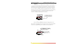
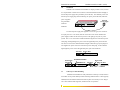
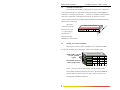
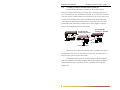
1
Corporate Headquarters
GarrettCom, Inc.
47823 Westinghouse Dr.
Fremont, CA 94539
Phone (510) 438-9071
Fax (510) 438-9072
Website: http://www.GarrettCom.com
Magnum ST80 Stackable
Personal Hub
email [email protected]
Installation and User Guide
www . GarrettCom . com
www . GarrettCom . com
Stackable Personal Hubs
Installation and User Guide (04/01)
Magnum™ Stackable
Personal Hub ™
Installation and User Guide
Part #: 84-00029 (Rev B 04/01)
Trademarks
Ethernet is a trademark of Xerox Corporation
NEBS is a trademark of Telcordia Technologies
UL is a registered trademark of Underwriters Laboratories
GarrettCom, Magnum and Personal Switch are trademarks and Personal Hub is a
registered trademark of GarrettCom, Inc.
Important: The Magnum ST80 Stackable Personal Hub family contains no
user serviceable parts. Attempted service by unauthorized personnel shall
render all warranties null and void. If problems are experienced with
Magnum ST80 Stackable Personal Hub products, consult Section 6,
Troubleshooting, of this User Guide.
Copyright © 2001 GarrettCom, Inc. All rights reserved. No part
of this publication may be reproduced without prior written permission from
GarrettCom, Inc.
Printed in the United States of America.
www . GarrettCom . com
ii
Stackable Personal Hubs
Installation and User Guide (04/01)
Contacting GarrettCom, Inc
Please use the mailing address, phone and fax numbers and email address listed below:
GarrettCom, Inc.
47823 Westinghouse Dr.
Fremont, CA 94539
Phone (510) 438-9071
Fax (510) 438-9072
Website: http://www.GarrettCom.com
email [email protected]
Federal Communications Commission
Radio Frequency Interference Statement
This equipment generates, uses and can radiate frequency energy and if not
installed and used properly, that is in strict accordance with the manufacturer's
instructions, may cause interference to radio communication. It has been tested and
found to comply with the limits for a Class A computing device in accordance with the
specifications in Subpart J of Part 15 of FCC rules, which are designed to provide
reasonable protection against such interference when operated in a commercial
environment. Operation of this equipment in a residential area is likely to cause
interference, in which case the user at his own expense will be required to take
whatever measures may be required to correct the interference.
www . GarrettCom . com
iii
Stackable Personal Hubs
Installation and User Guide (04/01)
TABLE OF CONTENTS
Page
1.0 SPECIFICATIONS...................................................................................... 1
1.1. Technical Specifications .................................................................................. 1
1.2 ORDERING INFORMATION ......................................................................... 3
2.0 INTRODUCTION ....................................................................................... 4
2.1 Inspecting the Package and Product.................................................................. 4
2.2 Product Description ......................................................................................... 5
2.3 Features and Benefits........................................................................................ 8
2.4 Applications...................................................................................................... 9
3.0 INSTALLATION ............................................................................................ 11
3.1 Table-Top or Shelf Mounting ........................................................................ 11
3.2 Wall (or Vertical Surface) Mounting (for non-stacked units only) ................. 12
3.3 Combining and Mounting Stacked Units........................................................ 12
3.4 Twisted Pair Segment Connections ................................................................ 13
3.5 AUI Connection.............................................................................................. 13
3.6 BNC Connection (Model ST80-B only) ......................................................... 15
3.7 Fiber Optic Connection (Model ST80-F only)................................................ 15
3.8 Switchable Up-Link Option............................................................................ 16
3.9 Stacking the ST80 Personal Hubs................................................................... 16
3.10 Cascading ST80 Personal Hubs with the Up-Link port ................................ 18
4.0 OPERATION............................................................................................. 19
4.1 Functional Operation, Use of LED Indicators ................................................ 19
4.2 Using the Up-Link switch............................................................................... 20
4.3 Using the BNC internal termination switch (Model ST80-B only) ................ 20
4.4 Using the Stack Enable switch........................................................................ 21
5.0 TROUBLESHOOTING............................................................................. 22
5.1 Before Calling for Assistance ......................................................................... 22
5.2 When Calling for Assistance .......................................................................... 23
5.3 Return Material Authorization (RMA) Procedure .......................................... 23
5.4 Return Shipping and Packaging Information .................................................. 24
APPENDIX A: WARRANTY INFORMATION .................................................... 24
Revisions
Rev B 04/01 : Change the company name to GarrettCom, Inc. (Formerly it
was Garrett Communications). There are no changes to the content of the
material at this time
Rev A 06/95 : This revision is the initial release of the Magnum ST80 Stackable
Personal Hub user manual.
www . GarrettCom . com
iv
Stackable Personal Hubs
Installation and User Guide (04/01)
The Magnum Line
ETHERNET CONNECTIVITY PRODUCTS
"DESIGNED AND MANUFACTURED IN THE USA"
OVERVIEW
GarrettCom, Inc.offers the premium-quality Magnum™ line of Ethernet LAN
connectivity products with industry-standard functionality and built-in fiber
configurability. Magnum products are designed for use in demanding Carrier Class,
Industrial Grade and OEM applications where reliability is a primary consideration.
4K-Series Switches, 100 & 10Mbps, copper ports with optional fiber
port, with auto-negotiating full switching performance
Quad-Series Fiber Switches, 100 & 10Mbps, fiber and copper
ports, mixed-speed and mixed-media types, full switching
performance
“Outdoor” Ethernet Switch, for temperature uncontrolled locations
6 10/100 and 2 100Mb fiber ports, can be connected in strings
Mixed-Media Fiber Hub, 16-port Stackable, 10/100 auto-sensing
Dual Speed 8-port and 16-port Stackables, 10/100 auto-sensing
Stackable Hubs, SNMP Optional
10Mb series and 100Mb series, both w/ optional port modules
Personal Switches, 10/100Mb
8 port dual speed, Auto-negotiable with fiber option
Personal Hubs, 100Mb or 10/100Mb
8-port, with two switched ports (1 fiber built in)
Personal Hubs, 10Mb series
8-port + AUI, stackable to 5 high, + optional BNC of fiber port
8 or 9-port and 4 or 5-Port Personal Hubs, w/ man. up-link sw.
Media Converters, 10Mb and 100Mb series
All media combinations, incl. fiber ST, SC, mm., single mode
The “X-line” of configurable MiXed Media products:
Stackable Concentrators, SNMP optional, 13-Ports
Mini-Concentrators, 7 Ports, Repeaters, 2-Ports
Repeater Port Modules (RPMs), 6 types for Ethernet media
Bridge Port Modules (BPMs), 4 types, for segment isolation
Fan-Outs, 10Mb series
2, 4 and 8 Port Models
Transceivers, 10Mb and 100Mb series 10Mb Mini-Transceivers
and Coax Models, All Types Apr, 01
www . GarrettCom . com
Stackable Personal Hubs
1.0
SPECIFICATIONS
1.1.
Technical Specifications
Installation and User Guide (04/01)
Performance:
Data Rate: 10 Mbps
Partitioning: Enforced after 32 consecutive collisions.
Reconnect: Occurs after 512 bits error-free transmission.
Maximum Ethernet Segment Lengths:
10BASE-T (Unshielded twisted pair) - 100 m (328 ft)
10BASE-T (Shielded twisted pair) - 150m (492 ft)
AUI Drop Cable
- 50 m (164 ft)
10BASE2 ThinNet (BNC)
- 185 m (607 ft)
10BASE5
- 500 m (1,640 ft)
10BASE-FL multi-mode Fiber optic - 2 km (6562 ft)
Network Standards:
Ethernet V1.0/2.0 IEEE 802.3: 10BASE-T, 10BASE5, 10BASE2,
10BASE-FL, FOIRL.
(Magnum Stackable Personal Hubs are physical layer standard Ethernet
products, and operate in networks independently of all software.)
Operating Environment:
Ambient Temperature: 32ºF to 122ºF (0ºC to 50ºC)
Storage Temperature: -20ºC to 60ºC
Ambient Relative Humidity: 10% to 95% (non-condensing)
Power Supply (External):
Input:
95 - 125 vac at 60 Hz for "-d" Models,
200 - 250 vac at 50 Hz for "-i" Models, which have
IEC power cable connector in the external power unit.
Output: 12 VDC, 1 A
Polarity: center positive, shell negative
Power Consumption: 12 watts max.
Connectors:
ST80: Eight shielded RJ-45 ports (one with up-link switch); one rear AUI,
female, with slide lock; two Inter-Repeater-Bus connectors on the side.
ST80-B: Same as ST80, plus one rear BNC with internal termination switch.
ST80-F: Same as ST80, plus one rear Fiber ST-type.
(Shielded 10BASE-T connectors accept either unshielded or shielded wiring
plugs for standard twisted pair media wiring.)
The regular RJ-45 ports support the standard for hubs-to-users twisted
pair wiring: pin 1= receive+, 2 = receive-, 3 = transmit+, 6 = transmit-,
other pins not used. The RJ-45 port with the up-link switch is normally
the same, but when switched it supports the standard for up-links using
twisted pair wiring, i.e., the transmit and the receive pairs are exchanged:
pin 1 = transmit+, 2 = transmit-, 3 = receive+, 6 = receive- , other pins
not used.
www . GarrettCom . com
1
Stackable Personal Hubs
Installation and User Guide (04/01)
Switches:
Up-Link: MDI-X (Media Dependent Interface - Crossover) manual slide
switch, converts RJ-45 port #8 from a regular (=) user segment port to a
crossover (X) up-link port for on-off connection to a backbone or another
cascaded hub.
Stack Enable Switch: Manual slide switch to specify which Stackable
Personal Hub is the base of the stack. Exactly one hub should have its Stack
Enable switch in the “OFF” position (left). All other hubs in the stack should
have their Stack Enable switches set to the “ON” position (right).
Internal Termination Switch (ST80-B only): When switched to the right
position, allows BNC connection without a “tee” connector and a 50 ohm
terminator. When switched to left position, a “tee” connector is required.
LEDs:
PWR: GREEN when Proper DC power supplied to ST80.
COL: YELLOW when a transmit collision occurs on the hub.
LINK/TX (per port): GREEN when link established on port. Flickers as
port transmits packets.
POL/RX (per port): Flickers GREEN as port receives packets. Steady
GREEN when reversed polarity detected.
Packaging:
Enclosure: Rugged, high strength steel enclosure.
Suitable for vertical or horizontal mounting.
Any unit may be used stand-alone, or as either the base unit or an additional
unit in a stack (two stacking / mounting clips and one IRB cable are
included with each unit)
Recessed LEDs to avoid damage, located with the RJ-45 ports for convenience.
Dimensions:
All models: 6.75 in x 4.0 in x 1.0 in (17.1 cm x 10.1 cm x 2.5 cm)
Weight:
All models:
1.3 lb. (600 gr.)
Power Supply: 1.0 lb. (455 gr.)
Cooling method:
Convection
Agency Approvals:
Magnum ST80 is UL Listed (UL1950), CSA certified
115v 60 Hz Power Supply is UL Listed, CSA certified.
230v 50 Hz Power Supply is same, also GS approved.
Emissions: Meets FCC Part 15, Class A
Warranty:
Three years (see also Appendix A)
Made in USA
www . GarrettCom . com
2
Stackable Personal Hubs
1.2
Installation and User Guide (04/01)
Ordering Information
Magnum Stackable Personal Hubs
MODEL
DESCRIPTION
Magnum ST80-d
Stackable Personal Hub with eight standard RJ-45 ports, one
with up-link switch, plus one rear AUI port; external 115 vac
60 Hz power supply.
Magnum ST80-i
Same as ST80-d, but with external 230 vac 50 Hz power
supply.
Magnum ST80-B-d Stackable Personal Hub with eight standard RJ-45 ports, one
with up-link switch; one AUI plus 1 BNC port with internal
termination switch; external 115 vac 60 Hz power supply.
Magnum ST80-B-i Same as ST80-B-d except with external 230 vac 50 Hz
power supply.
Magnum ST80-F-d Stackable Personal Hub with eight standard RJ-45 ports, one
with up-link switch; one AUI plus one Fiber-ST port with
LINK LED; external 115 vac 60 Hz power supply.
Magnum ST80-F-i Same as ST80-F-d except with external 230 vac 50 Hz
power supply.
GarrettCom, Inc. reserves the right to change specifications, performance
characteristics and/or model offerings without notice.
www . GarrettCom . com
3
Stackable Personal Hubs
2.0
Installation and User Guide (04/01)
INTRODUCTION
This section describes the ST80 Stackable Personal Hub, including appearance,
features and possible applications.
2.1
Inspecting the Package and Product
Examine the shipping container for obvious damage prior to installing this
product; notify the carrier of any damage which you believe occurred during shipment or
delivery. Inspect the contents of this package for any signs of damage and ensure that
the items listed below are included.
This package should contain:
1
Magnum ST80-series Stackable Personal Hub
1
External Power Supply, either 115v 60 Hz or 230v 50 Hz
1
Velcro® Tape section, approximately 3 inches in length
2
L-shaped stacking /mounting brackets
4
Metal screws for optional use with stacking/mounting brackets
1
Installation and User Guide
1
Product Registration Card
Remove the Magnum Stackable Personal Hub from the shipping container. Be
sure to keep the shipping container should you need to ship the unit at a later date. To
validate the product warranty please complete and return the enclosed Product
Registration Card to GarrettCom, Inc. as soon as possible.
In the event there are items missing or damaged, contact your supplier. If you
need to return the unit, try to use the original shipping container. Refer to Section 5,
Troubleshooting, for specific return procedures.
www . GarrettCom . com
4
Stackable Personal Hubs
2.2
Installation and User Guide (04/01)
Product Description
The Stackable Personal Hub is an eight-port + workplace hub in a very
compact package. It is simple to install and use in an office or lab environment,
requiring no special rack cabinets or wiring closet apparatus. Up to five Stackable
Personal Hubs may be stacked to form a single logical repeater. Personal Hubs are
standard physical layer Ethernet products and operate independently of all software.
ST80 Personal Hubs are well suited for small- to-medium-size office or lab
environments (up to eight users without stacking) that need an independent Ethernet
network. They can operate as self-sufficient units to provide 10BASE-T Ethernet
connectivity for local users and devices. Small independent networks built using
Stackable Personal Hubs are easily expanded by stacking additional ST80s via the IRB
connectors. The AUI port provides backbone or other connectivity if required. (The
ST80-B and ST80-F models are also equipped with a BNC or a Fiber-ST connector for
convenient media connections.)
B1
IR
PWR
AUI
B2
IR
S
O tack
FF E
na
b
O le
N
Magnum ST80 Stackable Personal Hub
Ports
1
2
3
4
5
6
7
8
UP-LINK
Network
Port
Stackable Personal Hubs provide a simple and inexpensive solution for
networking a multi-system office using 10BASE-T twisted pair cabling. They can
expand an existing single-network-port outlet to provide up to seven additional RJ-45
ports in the immediate office or lab area. Once installed, a Stackable Personal Hub is
easily expanded by stacking additional units to support larger numbers of users.
The Magnum ST80s’ small size makes them very useful for demonstration
situations in conference rooms and in exhibitions where a temporary network or network
expansion is needed. They are handy as a piece of test equipment that can be easily
inserted into a network to provide a test port, and then removed after the testing is done.
Stackable Personal Hubs take up minimal space, use minimal power, and are rugged
enough to be carried in a coat pocket for possible emergencies.
www . GarrettCom . com
5
Stackable Personal Hubs
Installation and User Guide (04/01)
ST80 Personal Hubs fit easily into the workplace environment. They are
versatile enough to be table-top or shelf-mounted. Alternatively, the brackets included in
the package may be used to mount a single (un-stacked) unit on a wall or any suitable
vertical surface. All of the wiring connectors are in the same plane so that wiring space is
neat and minimal. The external power supply unit conveniently plugs into an AC wall
receptacle or power strip.
BNC Internal
Termination Swtich
(ST80-B only) Power Jack
10BASE2 (BNC) Port (ST80-B only)
Fiber (ST) PORT (ST80-F only)
AUI Port
Stack Enable
Switch
IR
PWR
B1
IR
B2
le
ab N
En O
ck
Sta FF
O
IRB
Connectors
Up-Link Switch
AUI
Magnum ST80 Stackable Personal Hub
UP-LINK
Ports
1
2
Status LEDs
3
4
5
6
7
Front Ports
8
Switchable
Up-Link Port
The ST80's RJ-45 ports support connection of up to eight workstations or other
network devices over full length 10BASE-T cable segments. Stackable Personal Hubs
operate in compliance with the IEEE 802.3 specification for repeater functionality to
perform signal amplification, re-timing of data packets, and regeneration of preamble bits
for each packet received. Consistent with IEEE 802.3 specifications, Stackable Personal
Hubs will detect collisions, extend collision fragments, and automatically partition and
re-connect individual ports in order to keep problems on one segment from causing
downtime elsewhere on the network.
Model ST80 Personal Hubs include per port LINK/TX and POL/RX LEDs, a
COLlision LED and a DC PWR LED, all conveniently located on the front of the unit.
The LINK/TX LED illuminates GREEN when functional link is detected on the port. It
is intermittently turned off as the port transmits a packet. The POL/RX LED
intermittently illuminates GREEN as the port receives packets. If improper polarity is
detected, the LED is steady GREEN (the ST80 automatically compensates for the
polarity reversal and resumes normal operation). If the port becomes partitioned, the
LINK/RX and POL/TX LEDs will blink alternately. The COL LED flashes YELLOW
whenever a transmit collision occurs on any of the ports.
www . GarrettCom . com
6
Stackable Personal Hubs
Installation and User Guide (04/01)
The external power supply unit supplied is one of two types; one version for
AC input power of 115 vac 60 Hz, and one version for 230 vac 50 Hz. The 115 vac
version has a small transformer integral with a convenience power outlet plug. The 230
vac version has a small transformer integral with an IEC-type power plug for a usersupplied AC power cord with a convenience power outlet plug. Both types also include
a lightweight DC power cord to the applicable power jack on the ST80 unit.
www . GarrettCom . com
7
Stackable Personal Hubs
2.3
Features and Benefits
ν
Expandable Design
Installation and User Guide (04/01)
When network needs grow, several Stackable Personal Hubs can be easily
stacked to form a single logical repeater of up to forty RJ-45 ports.
ν
Low cost, stand-alone 10BASE-T connectivity
Operating in a stand-alone environment as self-sufficient devices,
Stackable Personal Hubs offer a very low cost method of providing small
workgroups access to a variety of Ethernet networking services such as file
sharing, E-Mail, printer sharing, and other computer information.
ν
Interconnect to an Existing Ethernet Network
Stackable Personal Hubs provide a manual Up-Link switch that allows one
RJ-45 port to connect into an existing Ethernet environment (such as the
central hub for the building or area) via 10BASE-T wiring.
ν
Inter-operable with other Ethernet Devices
Stackable Personal Hubs are completely inter-operable with other Ethernetcompliant network devices. Each is fully compliant with IEEE 802.3
specifications for 10 Mbps CSMA/CD operation, and can be integrated within
any standard Ethernet network and operate with standard software.
ν
Installation Versatility
Stackable Personal Hubs are easy to install in most any office or lab location.
The tiny package is very unobtrusive and may even be Velcro mounted.
ν
LEDs Simplify Network Installation and Maintenance
Stackable Personal Hubs are equipped with a full complement of LEDs to
provide status about basic network activity. LINK LEDs for each port offer a
simple way to verify operational connections of each 10BASE-T segment.
ν
High Quality
Stackable Personal Hubs have a rugged steel case and are compliant with rigid
CE emission standards, making them suitable for commercial and home
offices. Per-port partitioning and re-connection avoids most downtime.
www . GarrettCom . com
8
Stackable Personal Hubs
2.4
Installation and User Guide (04/01)
Applications
Expanding from one to multiple ports at an existing site is easy, and requires
no modification to typical building wiring. Simply plug the existing networked device's
network cable into one of the ST80’s front RJ-45 ports. The Up-Link port (with switch
set to “X”) connects via 10BASE-T cabling to the existing network outlet. Optionally, a
mini-transceiver may be connected to the rear-mounted AUI port to provide connectivity
to any standard Ethernet media type. (The ST80-B and ST80-F provide for direct
connection to 10BASE2 and multi-mode Fiber respectively).
Port 8 Switchable
Up-Link set to “X”
...to existing network via
switchable Up-Link port.
IR
PWR
AUI
B1
IR
B2
St
O ac
FF k
Magnum ST80 Stackable Personal Hub
na
bl
O e
N
E
UP-LINK
Ports
1
2
3
4
5
6
7
8
Personal Workgroup
Power is connected by plugging the external power supply unit into an AC
power receptacle, and plugging the DC power plug into the jack on the back of the ST80.
In minutes, up to eight additional ports are available for other networked devices.
...to existing network via AUI,
BNC (ST80-B only), or Fiber ST
(ST80-F only) connector.
IR
PWR
AUI
B1
IR
B
2
St
O ac k
FF
Magnum ST80 Stackable Personal Hub
na
bl
O e
N
E
UP-LINK
Ports
1
2
3
4
5
6
7
8
Port 8 Switchable
Up-Link set to “==”
Personal Workgroup
www . GarrettCom . com
9
Stackable Personal Hubs
Installation and User Guide (04/01)
Stackable Personal
Rear port(s) may be used
for additional user(s).
B1
PWR
IR
B
stand-alone network for a
IR
Hubs may also be used as a
AUI
2
St
O ac
FF k
Magnum ST80 Stackable Personal Hub
Port 8 Switchable
Up-Link set to “==”
na
bl
O e
N
E
UP-LI NK
Ports
1
2
3
4
5
6
7
8
personal multi-user system
such as shown below. Up to
Personal Workgroup
eight RJ-45 user ports are
available where only 10BASE-T wiring is used, and full-length Ethernet segments are
supported on all ports. In this application, the Up-Link switch is in the straight-through or
“==” position so that port 8 is a user port, not an up-link to another hub.
When network requirements exceed the capacity of a single ST80, additional
hubs may be stacked to form a single logical hub. This stacking capability allows one to
build larger networks that are in compliance with the “four repeater rule” specified in the
Ethernet standards. As with a single ST80 unit, a stack may be connected to a backbone
through any standard Ethernet media. A stack of ST80s may also be cascaded as a unit
into another stack or hub.
Fiber backbone
connection
IR
PWR
AUI
1
B
B
IR
2
E
k
ac
St FF
O
Magnum ST80 Stackable Personal Hub
UP-LI NK
e
bl
na ON
IR
PWR
B1
IR
B
2
AUI
E
k
ac
St FF
O
Magnum ST80 Stackable Personal Hub
UP-LINK
e
bl
na ON
Ports
1
2
3
4
Ports
5
6
7
8
Up-Link
set to “X”
www . GarrettCom . com
10
1
2
3
4
5
6
7
8
Stackable Personal Hubs
3.0
Installation and User Guide (04/01)
Installation
Installation of a Stackable Personal Hub is a simple procedure. First, locate an
AC receptacle that is within six feet (2 meters) of the intended hub location and plug in
the external power supply unit (provided as part of the unit). The small DC power cord
from the power supply plugs into the matching rear power jack of the ST80, and when
S
O tack
FF
Ports
1
2
3
4
5
6
7
8
UP-LINK
the green PWR
En
ab
O le
N
power is applied
B2
IR
B1
IR
External
Power Supply
Magnum ST80 Stackable Personal Hub
PWR
AUI
LED will
illuminate.
Power Jack
The external power supply unit supplied is one of two types; one version for
AC input power of 115 vac 60 Hz, and one version for 230 vac 50 Hz. Examine the
power supply to make sure the version you have is the right type for your AC power
system. The 115 vac version has a small transformer integral with a convenience power
outlet plug, and a lightweight DC power cord to the applicable power jack on the hub.
The 230 vac version has a small transformer integral with an IEC-type power plug for a
user-supplied AC power cord with a convenience power outlet plug. It also includes a
lightweight DC power cord to the applicable power jack on the ST80 unit.
AUI Port
Power Jack
Rear View - ST80
Power Jack
AUI Port
Termination Switch
AUI Port
10BASE2 Port
Rear View - ST80-B
3.1
Power Jack
Fiber ST Port
Rear View - ST80-F
Table-Top or Shelf Mounting
Stackable Personal Hubs are easily mounted on a table-top or shelf, and have
four rubber feet to provide stability without scratching finished surfaces. When properly
installed, the front-mounted status LEDs will be in plain view and easy to read. Plug in
two or more Ethernet cable segments, and the network is in operation.
www . GarrettCom . com
11
Stackable Personal Hubs
Installation and User Guide (04/01)
The rugged steel case of the ST80 Personal Hub will protect it from accidental
damage in an office or lab workplace setting. Keep an open area around the unit so that
convection cooling can occur while the unit is in operation.
3.2
Wall (or Vertical Surface) Mounting (for non-stacked units only)
When the Stackable Personal
Hub is being used as a single unit, the
stacking/mounting brackets may be used to
mount the unit on a wall or any
convenient surface where the associated
Proper attachment of stacking/
mounting bracket for wall mounting
cables are out of the way. The brackets
are attached to each side of the ST80’s case using one of the metal screws for each
PWR
+
AUI
IRB1
bracket. The brackets should be
Magnum ST80 Stackable
IRB2
Personal Hub
attached to the ST80 through the round
Stack Enable
OFF | ON
hole of the bracket. When properly
UP LINK
Ports 1
2
3
4
5
6
7
attached, the brackets will extend
8
slightly below the base of the unit to
Top view - One non-stacked ST80 with
brackets attached for wall mounting
3.3
allow clearance for the rubber feet.
Combining and Mounting Stacked Units
When stacking two or more ST80s, the stacking/mounting brackets should be
used to attach each additional unit to the one below it. First, attach two brackets to the
bottom of the upper unit, using two of the metal screws. To ease installation, attach the
brackets to the bottom of each unit
through the round holes of the
brackets. The brackets should be
oriented so that they extend down
Upside-down view - ST80 with
brackets attached for stacking
and out when the unit is upright.
Next, set the upper unit on top of the lower unit, so that the slotted holes of the
two brackets line up with the screw holes in the side of the lower ST80. Attach the
brackets to the lower unit with the two remaining screws. If additional units are to be
www . GarrettCom . com
12
Stackable Personal Hubs
Installation and User Guide (04/01)
included in the stack, attach them in the same manner. (The brackets and screws
included with the bottom unit of the stack will
not be used for stacking purposes.)
3.4
Twisted Pair Segment Connections
1. Using standard 10BASE-T media,
Proper attachment of ST80s with
stacking/mounting bracket
insert the male plug on one end of the network
cable into one of the RJ-45 female ports on the
Stackable Personal Hub. Even though the hub's
ports are of the shielded type, they will accept and operate properly with both shielded
and unshielded type RJ-45 twisted pair wiring.
B1
B2
IR
na
b
O le
N
S
O tack
FF E
each wiring cable to the applicable
IR
2. Connect the other end of
PWR
AUI
Magnum ST80 Stackable Personal Hub
Ports
1
2
3
4
5
6
7
8
UP-LINK
workstation or user device. The port’s
LINK LED illuminates when the
connection is made on both ends of the
wire, and when the DC power is on at
RJ-45 User Connections
each end, i.e., when the segment
circuit is established and is ready to use.
3. For the port 8 up-link feature, see 3.8.
3.5
AUI Connection
Using the steps below as a guide, attach a new or existing 10BASE5 ThickNet drop-
cable directly to the AUI connector on the rear of the ST80 Personal Hub.
1. Plug the male end of the cable into the female AUI connector on the ST80.
2. Engage the AUI connector slide lock to insure maximum connectivity.
3. Connect the opposite end of the cable into a network AUI port. (This could be a
network backbone transceiver, a hub or fan-out with an AUI port, or an AUI Port Module in
a concentrator.)
www . GarrettCom . com
13
Stackable Personal Hubs
Installation and User Guide (04/01)
The AUI port may also used for connecting to other Ethernet devices using
standard AUI cabling. In this type of situation, it is important to consider the AUI segment
length to the attached device, including any cascading.
The maximum transmission distance between a backbone transceiver and the AUI
port of the ST80 will vary. According to Ethernet standards, when an AUI cable is used to
connect the ST80 directly to a backbone transceiver, the maximum AUI segment length of
50m (165 ft.) is allowed. If the ST80 is connected to a transceiver that has been cascaded
from another transceiver, the maximum AUI segment length is reduced. See the following
note.
Important Note: The maximum transmission distance is decreased by 6m (20
ft.) for every additional level of network transceiver device "dropped" or
"cascaded" from the original backbone transceiver tap.
The AUI connector of the Stackable Personal Hub supports standard IEEE signals,
which are summarized in Table 3.5
Table 3.5 AUI Pin Assignments
Pin
1
2
3
4
5
6
7
8
9
NOTES:
Function
Pin
Function
Control In Circuit Shield
10
Data Out Circuit B
Control In Circuit A
11
Data Out Circuit Shield
Data Out Circuit A
12
Data In Circuit B
Data In Circuit Shield
13
Voltage Plus (+)
Data In Circuit A
14
Voltage Shield
Voltage Common
15
Control Out Circuit B
Control Out Circuit A
SHELL Protective Ground
Control Out Circuit Shield (conductive shell)
Control In Circuit B
1)
Voltage Plus (pin #13) and Voltage Common (pin # 6) use a single
twisted pair in the AUI cable.
2)
Pins 4, 8, 11 and 14 may be connected to pin #1.
www . GarrettCom . com
14
Stackable Personal Hubs
3.6
Installation and User Guide (04/01)
BNC Connection (Model ST80-B only)
Connect the ThinNet coax cable to the BNC connector on the rear of the ST80-B in
the same manner as is done for any standard BNC connection. The BNC port is specially
equipped with an internal termination switch that eliminates the need to use a "tee" connector
when the BNC cable is ending at the ST-80. When the switch is in the right position, the
connection is internally terminated. When switched to the left position, external termination
(“tee” connector, not supplied) is required. Some applications may require a "tee" connector,
used as a tap, to allow the 10BASE2 coax segment to continue on past the ST-80 port
connection.
3.7
Fiber Optic Connection (Model ST80-F only)
The following procedure applies to FOIRL and 10BASE-FL multi-mode applications
using an ST80-F. (The primary difference between FOIRL and 10BASE-FL for users is the
maximum distance allowed. 10BASE-FL is used for a fiber segment length of up to 2000m,
while FOIRL is used for fiber segments of up to 1000m in length.)
1.
Before connecting the fiber optic cable, remove the protective dust caps from the
tips of the connectors on the ST80’s rear Fiber port. Save these dust caps for future use.
2.
Wipe clean the ends of the dual connectors with a soft cloth or lint-free lens tissue
dampened in alcohol. Make certain the connectors are clean before connecting.
Note: One strand of the duplex fiber optic cable is coded using color bands at
regular intervals; you must use the color-coded strand on the associated ports at
each end of the fiber optic segment, i.e., TX on one end and RX on the other end.
3.
Connect the Transmit (TX) port (light colored post) of the ST80 to the Receive
(RX) port of the remote device. Use the color-coded strand of the cable for this first TX-toRX connection.
4.
Connect the Receive (RX) port (dark colored post) of the ST80 to the Transmit
(TX) port of the remote device. Use the non-color coded fiber strand for this connection.
5.
The LINK LED next to the rear fiber port will illuminate when a proper connection
has been established at both ends (and when power is ON in the unit). If LINK is not lit after
cable connection, the normal cause is improper cable polarity. Swap the fiber cables at the
ST80’s rear fiber port connectors to remedy this situation in most cases.
www . GarrettCom . com
15
Stackable Personal Hubs
3.8
Installation and User Guide (04/01)
Switchable Up-Link Feature
Each Stackable Personal Hub is equipped with an up-link switch, connected to
port 8 (right-most RJ-45 port). This switch is used to select either a normal 10BASE-T
connection to a user device (switch in the “==” position) or a 10BASE-T network up-link
connection to another hub or concentrator (switch in the “X” position). A special
crossover cable for up-link is not needed with the Stackable Personal Hub because of this
built-in up-link switch feature.
PWR
AUI
2
3
4
5
6
7
8
(X
1
UP-LINK
U
pLi
nk
B1
B2
IR
na
b
O le
N
Ports
)
Magnum ST80 Stackable Personal Hub
S
O tack
FF E
is wired for up-link but
IR
When port 8
the switch is set to the
se
r(
==
)
“==” position, the up-
U
link connection is
inoperative and full
bandwidth is available locally.
3.9
Stacking the ST80 Personal Hubs
When increased network capacity is needed, up to five ST80 Personal Hubs
may be easily stacked to form a single logical repeater of up to 40 RJ-45 ports.
IR
PWR
IR
B2
le
ab N
En O
ck
Sta FF
O
Stack Enable Switches
in “ON” position
(right)
B1
AUI
Magnum ST80 Stackable Personal Hub
UP-LINK
Ports
1
2
3
4
5
6
7
8
Stack Enable Switch in
“OFF” position (left)
NOTE: Be sure to secure the units with the stacking/mounting brackets
before making the following electrical connections. The brackets cannot be
installed while the connector cables are in place. Refer to Section 3.3 for
stacking bracket installation instructions.
www . GarrettCom . com
16
Stackable Personal Hubs
Installation and User Guide (04/01)
When stacking, switch the
Stack Enable switch of the bottom
IR
B1
PWR
IR
B2
le
ab N
En O
ck
Sta FF
O
ST80 to the “OFF” position (left). All
AUI
Magnum ST80 Stackable Personal Hub
UP-LINK
Ports
1
2
3
4
5
6
7
8
other units should be switched to the
“ON” position (right). Using the IRB
ribbon cable, connect one end to
Two stacked ST80s - 16 RJ-45 ports
either Inter-Repeater-Bus connector
IR
B1
PWR
IR
B2
le
ab N
En O
ck
Sta FF
O
(IRB1 or IRB2) of the bottom ST80.
Connect the other end of the cable to
AUI
Magnum ST80 Stackable Personal Hub
UP-LINK
Ports
1
2
3
4
5
6
7
8
the corresponding IRB connector of
the top ST80 (i.e., the IRB cable is
connected from IRB1 to IRB1, or from
IRB2 to IRB2). If additional ST80
Personal Hubs are to be added,
Three stacked ST80s - 24 RJ-45 ports
IR
B1
PWR
IR
B2
le
ab N
En O
ck
Sta FF
O
connect another IRB cable from the
AUI
Magnum ST80 Stackable Personal Hub
UP-LINK
Ports
1
2
3
4
5
6
7
8
unused IRB connector of the existing
stack’s top unit to the corresponding
IRB connector of the ST80 Personal
Hub to be added. Be sure that the
Stack Enable Switch of the added unit
is set to the “ON” position. Up to five
Four stacked ST80s - 32 RJ-45 ports
Stackable Personal Hubs may be
IR
B1
PWR
IR
B2
le
ab N
En O
ck
Sta FF
O
connected in this fashion.
AUI
Magnum ST80 Stackable Personal Hub
Ports
1
2
3
PWR
4
5
6 AUI
UP-LINK
7
8
Magnum ST80 Stackable Personsal Hub
Each unit of the stack must be
UP-LINK
Ports
1
2
3
4
5
6
7
powered by its own external power
supply unit. “Power on” is verified by
observing that the PWR LED of each
unit is illuminated. Should one unit of
the stack be powered down, the
remainder of the stack will still function
Five stacked ST80s - 40 RJ-45 ports
properly.
Increased port capacity via stacking
www . GarrettCom . com
17
8
Stackable Personal Hubs
3.10
Installation and User Guide (04/01)
Cascading the ST80 Personal Hub with the Up-Link port
Stackable Personal Hubs may be cascaded in order to expand existing
networks. For example, an ST80 may be cascaded via the switchable up-link port into
any port of another hub. Also, Stackable Personal Hubs may be connected to a backbone
via the rear AUI port. With the addition of a mini-transceiver, the AUI port may be used
to connect to any standard Ethernet media. (ST80-B and ST80-F Personal Hubs may
connect directly to 10BASE2 and multi-mode Fiber, respectively.) Since each ST80
provides full repeater functionality, cascaded units can operate together even though
there may be a full segment of distance between them.
IR
3
4
5
6
PWR
7
8
AUI
B2
B1
IR
B
2
St
O ac
FF k
4
5
6
7
8
St
O ac
FF k
na
bl
O e
N
E
UP-LINK
3
B2
2
2
PWR
IR
B1
IR
na
bl
O e
N
E
1
1
B1
IR
St
O ac
FF k
Ports
Magnum ST80 Stackable Personsal Hub
Ports
Port 8 Up-Link
switch in == position
Port 8 Up-Link
switch in X position
AUI
UP-LINK
IR
PWR
Magnum ST80 Stackable Personal Hub
AUI
Magnum ST80 Stackable Personal Hub
na
bl
O e
N
E
UP-LINK
Ports
1
2
3
4
5
6
7
8
IR
PWR
AUI
B1
IR
B
2
O
St
ac
FF k
Magnum ST80 Stackable Personal Hub
O
En
UP-LINK
ab
N
le
Ports
1
2
3
4
5
6
7
8
Users and devices
Users and devices
Users and devices
Based on the "four repeater rule" defined by Ethernet standards, there may be a
maximum of four units in any one chain between any two users. Note that a stack of
ST80s is a single “unit” for repeater functionality.
Magnum ST80 hubs may also be cascaded in networks with other Magnum
Hubs (such as Magnum Personal Hubs, Magnum 1000 Workgroup Hubs, and Magnum
3000 Stackable Hubs and Concentrators) as well as with Ethernet hubs from other
manufacturers.
www . GarrettCom . com
18
Stackable Personal Hubs
4.0
Installation and User Guide (04/01)
OPERATION
This section details the various operational features of Magnum ST80 Personal
Hubs, including a description of the LED indicators. Stackable Personal Hubs are fully
compliant with the Ethernet Version 2/IEEE 802.3 Repeater Specification for CSMA/CD
10 Mbps operation and will function accordingly.
4.1
Functional Operation, Use of LED Indicators
Power On (PWR) LED: Illuminates GREEN to show proper DC power.
Collision (COL) LED: Illuminates YELLOW whenever a transmit collision
occurs on a port within the hub.
Link Status and Transmit (LINK/TX) LED: Per port LEDs detect and
indicate by illuminating GREEN that there is proper connectivity on a 10BASET network segment. The LED will turn off intermittently when the port
transmits a packet. In the event that connectivity is lost between the ends of that
segment or a loss of power occurs in the segment at either end, the LED is
turned off.
Note: When port 8 is wired for up-link to another hub, the LINK LED
will normally be on when the up-link switch is set to the “X” position. With the
up-link switch off (“==”), LINK is off as the up-link is disabled. This permits
local operation of the ST80 Personal Hub with full bandwidth.
Polarity and Receive (POL/RX) LED: Per port LEDs intermittently
illuminate GREEN to indicate that data packets are being received from the
segment. This provides a visual indication of network activity for re-assurance
of normal operation, and is also helpful in troubleshooting. If reversed polarity
is detected, the LED becomes steady GREEN (the ST80 automatically
compensates for the reversed polarity and resumes normal operation).
Partitioning and Re-connection: Stackable Personal Hubs will automatically
partition any port where 32 consecutive collisions or 6.5 ms of continuous
transmissions occurs. Network integrity is checked every 800 ms and segment
re-connection occurs after one 512-bit packet is transmitted without error. The
status LEDs of a partitioned port indicate the partitioned state by blinking
alternately.
www . GarrettCom . com
19
Stackable Personal Hubs
Installation and User Guide (04/01)
Preamble Regeneration: Stackable Personal Hubs add preamble bits so that
output packets contain a minimum 64-bit preamble per the Ethernet standard.
Collisions: When carrier is detected simultaneously on multiple ports, a jam
pattern is generated on each port to create a collision condition. When a
collision signal from one port is detected, it generates a jam pattern to other
ports.
Fragment Extension: Stackable Personal Hubs will automatically add bits to a
received data packet of less than 96 bits (a "fragment") so that the minimum
output packet to the other port is 96 bits long.
4.2
Using the Up-Link switch
Port 8 of the ST80 is equipped with an up-link switch to allow
connection to another hub or concentrator without a special crossover cable.
When set to the “=” position, port 8 is set up as a user port. When the switch is
in the “X” position, port 8 operates as an up-link port. To ensure that the uplink switch is in the proper position, observe port 8’s LINK/TX LED. If this
LED is illuminated or flickering, the switch is properly set. If it is off, try the
other switch position. If neither position seems to work, check the 10BASE-T
cable and the connected device for proper installation. For more information on
the up-link switch, see Sections 3.8 and 3.10, “Switchable Up-Link Option” and
“Cascading the ST80 Personal Hub with the Up-Link port”.
4.3
Using the BNC Internal Termination Switch (Model ST80-B only)
Model ST80-B is equipped with a rear-mounted BNC connector with an
internal termination switch. This switch allows connection to 10BASE2 cable without
use of an external “T” type terminator. When set to the left position, external termination
is required. When the switch is in the right position, the connector is internally
terminated. For more details on the internal termination switch, see Section 3.6, “BNC
Connection”.
www . GarrettCom . com
20
Stackable Personal Hubs
4.4
Installation and User Guide (04/01)
Using the Stack Enable switch
The Stack Enable switch of the ST80 is used to configure each unit of the
stack. If an ST80 is being used as a non-stacked unit, the Stack Enable switch must be in
the “OFF” position. When two or more ST80s are stacked, the bottom unit should be set
to the “OFF” position, and all other units should be in the “ON” position. For further
information about the Stack Enable switch, see Section 3.9, “Stacking the ST80s”.
www . GarrettCom . com
21
Stackable Personal Hubs
5.0
Installation and User Guide (04/01)
TROUBLESHOOTING
All Magnum Ethernet products are designed to provide reliability and consistently
high performance in all network environments. The installation of Magnum ST80 Stackable
Personal Hub is a straightforward procedure (see INSTALLATION, Section 2.6); the
operation is also straightforward and is discussed in Section 4.
Should problems develop during installation or operation, this section is intended
to help locate, identify and correct these types of problems. Please follow the suggestions
listed below prior to contacting your supplier. However, if you are unsure of the procedures
described in this section or if the Magnum ST80 Stackable Personal Hub is not performing as
expected, do not attempt to repair the unit; instead contact your supplier for assistance or
contact GarrettCom Customer Support.
5.1
Before Calling for Assistance
1.
If difficulty is encountered when installing or operating the unit, refer back to the
Installation Section of the applicable chapter of this manual. Also check
to make sure
that the various components of the network are interoperable.
2.
Check the cables and connectors to ensure that they have been properly
connected and the cables/wires have not been crimped or in some way
impaired during installation. (About 90% of network downtime can be
attributed to wiring and connector problems.)
3.
Make sure that an AC power cord is properly attached to each Magnum ST80
Stackable Personal Hub unit. Be certain that each AC power cord is plugged into a
functioning electrical outlet. Use the PWR LEDs to verify each unit is receiving
power.
4.
If the problem is isolated to a network device other than the Magnum ST80
Stackable Personal Hub product, it is recommended that the problem device is
replaced with a known good device. Verify whether or not the problem is
corrected. If not, go to Step 5 below. If the problem is corrected, the Magnum
ST80 Stackable Personal Hub and its associated cables are functioning properly.
5.
If the problem continues after completing Step 4 above, contact your supplier of
the Magnum ST80 Stackable Personal Hub unit or if unknown, contact
GarrettCom, Inc.by fax, phone or email ([email protected]) for assistance.
www . GarrettCom . com
22
Stackable Personal Hubs
5.2
Installation and User Guide (04/01)
When Calling for Assistance
Please be prepared to provide the following information.
1.
A complete description of the problem, including the following points:
a. The nature and duration of the problem;
b. Situations when the problem occurs;
c. The components involved in the problem;
d. Any particular application that, when used, appears to create the problem;
2.
An accurate list of GarrettCom product model(s)involved, with serial number(s).
Include the date(s) that you purchased the products from your supplier.
3.
It is useful to include other network equipment models and related hardware,
including personal computers, workstations, terminals and printers; plus, the
various network media types being used.
4.
A record of changes that have been made to your network configuration prior
to the occurrence of the problem. Any changes to system administration
procedures should all be noted in this record.
5.3
Return Material Authorization (RMA) Procedure
All returns for repair must be accompanied by a Return Material Authorization
(RMA) number. To obtain an RMA number, please use this URL https://rma.garrettcom.com/rma/rma_request_noaccount.php to fill out the form. Please
have the following information readily available:
Name and phone number of your contact person.
Name of your company / institution
Your shipping address
Product name
Serial Number (or Invoice Number)
Packing List Number (or Sales Order Number)
Date of installation
Failure symptoms, including a full description of the problem.
GarrettCom will carefully test and evaluate all returned products, will repair products
that are under warranty at no charge, and will return the warranty-repaired units to the
sender with shipping charges prepaid (see Warranty Information, Appendix A, for
complete details). However, if the problem or condition causing the return cannot be
duplicated by GarrettCom, the unit will be returned as:
www . GarrettCom . com
23
Stackable Personal Hubs
Installation and User Guide (04/01)
No Problem Found.
GarrettCom reserves the right to charge for the testing of non-defective units
under warranty. Testing and repair of product that is not under warranty will result in a
customer (user) charge.
5.4
Shipping and Packaging Information
Should you need to ship the unit back to GarrettCom, please follow these instructions:
1. Package the unit carefully. It is recommended that you use the original container
if available. Units should be wrapped in a "bubble-wrap" plastic sheet or bag for
shipping protection. ( You may retain all connectors and this Installation Guide.)
CAUTION: Do not pack the unit in Styrofoam "popcorn" type packing
material. This material may cause electro-static shock damage to the unit.
2. Clearly mark the Return Material Authorization (RMA) number on the
outside of the shipping container.
3. GarrettCom is not responsible for your return shipping charges.
4. Ship the package to:
GarrettCom, Inc.
47823 Westinghouse Dr.
Fremont, CA 94539
Attn.: Customer Service
APPENDIX A: WARRANTY INFORMATION
GarrettCom, Inc. warrants its products to be free from defects in materials and
workmanship for a period of three (3) years from the date of shipment by
GarrettCom.
During this warranty period, GarrettCom will repair or, at its option, replace
components in the products that prove to be defective at no charge other than
shipping and handling, provided that the product is returned pre-paid to GarrettCom.
This warranty will not be effective if, in the opinion of GarrettCom, the
product has been damaged by misuse, misapplication, or as a result of service or
modification other than by GarrettCom.
GarrettCom reserves the right to make a charge for handling and inspecting
any product returned for warranty repair which turns out not to be faulty.
Please complete the warranty card as this acts as a product registration, and
mail it to GarrettCom within two weeks of your purchase.
www . GarrettCom . com
24