1
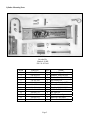
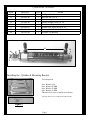
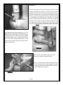
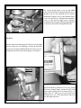
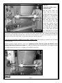
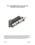
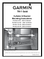
TR-1 Gold
Cylinder & Bracket
Mounting Instructions
Honda 8 HP: 2001 & Newer
Honda 9.9 HP: 2001 & Newer
Honda 15 HP: 2003 & Newer
Honda 20 HP: 2003 & Newer
Figure 1 Finished steering actuator
CAUTION: This kit fits the long and extra long shaft motors only. It will not fit the short shaft version.
Page 1
PN 906-1075-00
Cylinder Mounting Parts
10
13
11
12
14
6
5
4
7
2
11
8
3
Bracket Kit
Honda 8-20 HP
PN 120-1070-00
ITEM
2
3
4
5
6
7
8
10
11
12
13
14
PART No.
330-1071-01
330-1071-02
130-1072-00
330-1013-00
380-1074-00
380-1075-00
310-0260-90
130-0084-02
310-0067-25
310-0067-01
310-0067-02
310-2501-25
QTY
1
1
1
1
1
2
2
1
4
1
2
1
Page 2
NAME
Standoff, Upper (Short)
Standoff, Lower (Long)
Bracket, Rod Eye Mounting
Pin, Stern Pivot
Channel, Cylinder MTG.
Plate, Channel Doubler
Hex Cap M8 X 90 MM
“U” Bolt 2” ID 1/4-20
Lw, Split 1/4
Hair Pin Cotter Lg.
Hair Pin Cotter Med.
Clevis Pin 1/4 D. X 1.25
Cylinder Kit PN 120-0900-00
ITEM
31
33
34
35
36
37
38
40
PART NO.
330-1002-00
310-0042-09
340-0900-00
321-0001-00
330-1101-00
310-0040-26
328-0901-00
328-0902-00
QTY
1
1
1
2
1
1
2
1
NAME
Rod Eye, 5/16-24
Hex Jam Nut 5/16-24
Cylinder
Fitting, Straight 1/8 NPT X 1/4
Zinc Anode (Replaceable)
Washer, Flat, Nylon 1/4 ID X .03
Bushing 1/4 ID X 5/16 OD X 1/4”L
Cylinder Tail Bushing
35
38
40
34
I. Installing the Cylinder & Mounting Bracket
Tools Required:
One; Wrench ½ In.
One; Wrench 10 MM
One; Wrench 12 MM
One; Wrench 13 MM
Thread lock (Loctite or similar (not shown)
You may choose to use sockets and socket wrench.
Figure 2
Page 3
Step One:
Turn the steering friction lock in the motor (just above the
clamps and below the shift lever) all the way to the left.
(Full free steering rotation. See motor manual if necessary.)
The motor must steer very freely for the autopilot to work.
If there is still any drag in the steering loosen the nut that
is controlled by the friction lever to eliminate it. Tip the
motor to the down position. Remove the lower clamp bolt
from the lower motor vibration isolation mount. Be sure
the upper bolt is tight or the unit can slide down on the
inner shaft. Do not remove both bolts at the same time.
Figure 5
Put a little thread lock on the bolt. Install an 8
MM Bolt (item 8) through a Lock Washer (item
9), through the lower front hole in the Cylinder
Mounting Channel (item 6), both Doubler Plates
(item 7), the Lower Long Standoff (item 3), and
into the lower motor vibration isolation mount.
Lightly snug the bolt.
Figure 6
Now remove the upper clamp bolt from
the motor vibration isolation mount.
Tip: Use the bolt you removed from the lower
motor vibration mount in the upper hole of the
mounting channel to keep the channel doubler
plates aligned. See Figure 7.
Figure 7
Page 4
Put a little thread locker on the second 8MM
(item 8) bolt and install it through the other Lock
Washer (item 9), the sandwich of the Cylinder
Mounting Channel (item 6) and Doubler Plates
(item 7) created at Fig. 6, the upper Short Standoff
(item 2), and into the upper motor vibration
isolation mount. Keep the Channel perpendicular
to the motor down shaft and tighten the bolt.
Figure 8
Step Two:
Slide the small end of the Stern Pivot Pin (item 5) through
the holes at the rear of both flanges. Secure the Pivot Pin
in place by inserting a Medium Hair Pin Cotter (item 13)
through the hole below the bottom flange. See Figure 9.
Figure 10
Figure 9
Step Three:
Install the Rod Eye Bracket (item 4) by putting
the lower channel flange against the top of the
motor grease fitting boss (as shown in Fig. 10),
slide in the “U” Bolt (item 10), put on the Lock
Washers (item 11), a little thread lock, and screw
on and tighten the nuts.
Page 5
Figure 11-a
Figure 11
Step Four:
Put cylinder Rod Eye block (item 31) down over the pin in the Rod Eye Mounting Bracket (item 4). See
Figure 11-a. Turn the Cylinder (item 34) so that the Fittings (item 35) point up (toward the top of the
motor). Line the hole in rear end cap of the Cylinder (item 34) with the hole in the top of the Stern Pivot
Pin (item 5). Slide the Clevis Pin (item 14) into the top hole of the Stern Pivot Pin. Line up the cross holes
and put the Large Hair Pin Cotter (item 12) through the cross holes in both Pins. See Figure 11.
NOTE: If for any reason you
need to disconnect the steering
actuator, pulling the large Hair
Pin Cotter and Clevis Pin will
disconnect them quickly.
Step Five:
Install the Hair pin (item 13) on the pin in the
Rod Eye Mounting Bracket (item 4) and against
the Rod Eye block (item 31). See Figure 12.
Figure 12
Page 6
Step Six:
Adjust the cylinder travel
both directions.
Turn the motor hard over
to port. That will retract the
Cylinder rod into the Cylinder.
See Figure 13. Check that the
Cylinder rod is still free to
retract at least a little more.
Next turn the motor hard
over to starboard. That will
extend the Cylinder rod out
of the Cylinder. See Figure
14. Check that the Cylinder
rod is still free to extend at
least a little more. It should
Figure 13
have additional travel in both
directions. If it does not, adjust
the position of the Rod Eye block (item 31) on the end of the Cylinder shaft. The Cylinder shaft should turn
with your fingers if the Hex Jam Nut (item 33) is loose. (If the shaft does not turn freely enough, use a thin 1/4
Inch open end wrench at the shaft’s wrench flats and loosen the hex jam nut.)
Do not use any tool on the cylindrical part of the Cylinder shaft. If the shaft gets scratched, bent, or dinged
the seal will fail.
With the cylinder properly adjusted, secure it by tightening the Hex Jam Nut against the Rod Eye after
putting a little thread lock between them. It is ready for plumbing the hydraulic hoses. We suggest you put
the original parts to the motor in a container and, carefully, store them.
Figure 14
Page 7