1
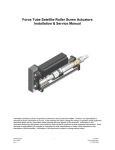
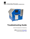
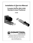
TR-1 Gold
Cylinder and Bracket
Mounting Instructions
OMC 9.9 HP. 2 & 4 Stroke: 1993-2002
OMC15 HP. 2 & 4 Stroke: 1993-2002
Page 1
PN 906-1005-00
Cylinder Kit PN 120-1005-01
Parts:
ITEM
3
4
5
6
7
11
12
14
15
17
18
19
PART No
330-1003-00
380-1004-00
370-1005-00
380-1006-00
130-1007-00
320-0010-00
310-0203-50
130-0083-00
310-2501-25
310-0067-01
310-0067-02
380-1010-00
6
QTY.
1
1
1
1
1
2
2
1
1
1
1
1
NAME
Pin, Stern Pivot
Channel, Cylinder MTG.
Cushion, Channel Mounting
Washer, Angle Plate
Assy, Mounting Bracket
3/16 D. Split Tube
Hex Cap 1/4-20 X 3-1/2” SS
Hose Clamp assembly
Clevis Pin 1/4 D. X 1.25
Hair Pin Cotter LG.
Hair Pin Cotter Med.
Spacer Plate
18
11
15
17
4
3
5
19
7
12
14
Figure 2
Page 2
Cylinder Kit PN 120-0900-00
ITEM
31
33
34
35
36
37
38
39
40
PART NO.
330-1002-00
310-0042-09
340-0900-00
321-0001-00
330-1101-00
310-0040-26
328-0901-00
320-0001-03
328-0902-00
QTY
1
1
1
2
1
1
2
2
1
NAME
Rod Eye, 5/16-24
Hex Jam Nut 5/16-24
Cylinder
Fitting, Straight 1/8 NPT X 1/4
Zinc Anode (Replace)
Washer, Flat, Nylon 1/4 ID X 3/8 OD x .03 Thick
Bushing 1/4 ID X 5/16 OD X 1/4”L
Vinyl Cap 1/4”
Cylinder Tail Bushing
39
35
38
34
I. Installing the Cylinder Mounts
Tools Required:
One; Wrench 9/32 In. or 7mm
One; 7/16 In. Wrenches
One; ½ In. wrenches (open end)
Thread lock (Loctite or similar)
Figure 3
Page 3
40
Step 1 (Mounting Bracket):
Tip the motor all the way up. Install the
Mounting Bracket Assembly (item 7)
over the motor steering swivel bracket as
shown in figure 4. Be sure groove in the
Bracket engages the ridge on the motor,
the Split Tube Pads (item 11) are on the
mounting ears, and the pads are on the
flats on the rear facing part of the swivel
bracket. Tighten all four screws.
Figure 4
Step 2 (Hose Clamp):
Open the Hose Clamp (item 14) and install it around
the shank of the motor’s steering pivot bracket and
over the tab on the bottom of the Mounting Bracket
Assembly (item 7). Before tightening the Hose
Clamp slide the urethane (rubber) pad (item 10)
under it and the tab on the bottom of the Mounting
Bracket Assembly to protect the finish on the motor.
With all in place, firmly tighten the Hose Clamp.
(Be sure the Hose Clamp screw does not interfere
with the steering rotation when the motor is turned
to steer it.)
Figure 5
Step 3 (Remove Bolts):
Tilt the motor down. Remove
the rear two bolts that holds the
lower vibration isolation mounting
shrouds. Leave the shrouds in
place.
Figure 6
Page 4
Step 4 (Mounting the Channel):
Slide the two Hex Cap Screws (item 9) through
the Angle Washer Plate (item 6). Keep the thick
edge to the right. Now slide the two Hex Cap
Screws (item 9) through the Cylinder Mounting
Channel (item 4). (With the label facing you
right side up, through the holes on the left end
from the near side.) Next slide the Screws
through the flat side of the Channel Mounting
Cushion (item 5). Keeping the thin side to the
right, apply the your thread lock compound to
the Screw threads. Last, slide the Screws all the
way through the holes in the lower vibration
isolation mounting shrouds. (The holes that
you just took the screws out of in the previous
step.) Keep the Channel perpendicular to the
motor down shaft and tighten the Screws. You
are ready for the Cylinder. (The thread lock
Figure 7
really is needed.)
Cylinder Mounting Instructions Supplement
It has been determined that some OMC 9.9-15 four stroke motors require the addition of a spacer plate
between the Channel Mounting Cushion (item 5 of the OMC instructions) and the Cylinder Mounting
Channel (item 4 of the OMC instructions).
The spacer plate (item
19) is installed between
the Channel (item 4) and
the Plastic cushion (item
5) The assembly stack in
step 4 of the manual will
look like the picture to the
right.
Page 5
Step 5 (Stern Pivot Pin):
Slide the Stern Pivot Pin (item 3)
through the back of the Cylinder
Mounting Channel (item 4) from the
top.
Loosen the steering tension device
to the minimum setting. (Refer to
your outboard owners manual.)
II. Installing the Cylinder
Tools Needed:
One; ½ In. Open end wrench
(from above, should be all you need)
Figure 8
Parts
Step 6 (Cylinder Rod Eye):
Place the Rod Eye (item 31) over the
vertical pin in the Mounting Bracket
Assembly (item 7) as shown. (Leave the
cylinder attached.) Put the plastic Washer
(item 18) on the pin over the Rod Eye
and install the Medium Hair Pin Cotter
(item 18) through the hole in the vertical
pin. Turn the Cylinder (item 34) Fittings
(item 35) up.
Figure 10
Page 6
Step 7 (Cylinder End Cap):
Line the hole in rear end cap of the Cylinder (item 34) with the hole in the top of the Stern Pivot Pin
(item 3). Slide the Clevis Pin (item 13) through the hole into the Stern Pivot Pin. Put the Large Hair
Pin Cotter (item 16) through the cross holes in both Pins (Under the Channel flange).
Figure 11
Page 7
Step 8 (Full
Starboard):
Port
and
Turn the motor hard over to
starboard. That will retract the
Cylinder rod into the Cylinder.
Check that the Cylinder rod is
still free to retract at least a little
more. Next turn the motor hard
over to port. That will extend the
Cylinder rod out of the Cylinder.
Check that the Cylinder rod is
still free to extend at least a little
more. It should have additional
travel in both directions. If it does
not adjust the position of the Rod
Eye (item 31) on the Cylinder Figure 12
shaft. The Cylinder shaft should
turn with your fingers if the Hex
Jam Nut (item 33) is loose. (If
the shaft does not turn freely
enough, use a thin 1/4 Inch open
end wrench at the shaft’s wrench
flats.) Do not use any tool on the
cylindrical part of the Cylinder
shaft. If the shaft gets scratched,
bent, or dinged the seal will
fail. With the cylinder properly
adjusted, secure it by tightening
the Hex Jam Nut against the Rod
Eye. It is ready for plumbing. We
suggest you put the original parts
in a container and store them.
(You may eventually want to sell
or trade in your motor, but we
know you will want to keep your
TR-1 autopilot.)
Figure 13
Page 8