1
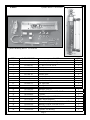
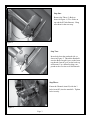
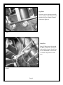
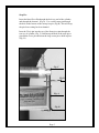
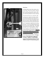
TR-1 Gold
Cylinder and Bracket
Mounting Instructions
Yamaha F-15 HP: 1998-2006
Yamaha F-9.9: 2003 and Newer
Yamaha T-9.9: 2005 - 2007 (Except 2007 Canadian T9.9)
Page 1
PN 906-1080-00
Parts:
Cylinder Kit PN 120-0900-00
Cylinder Mounting Kit PN 120-1080-00
ITEM
PART NUMBER
1
2
3
4
5
6
7
8
9
10
11
12
130-1082-00
380-1084-00
130-0084-02
310-0076-25
330-1013-00
310-2501-25
330-1081-02
330-1081-01
310-0067-02
310-0067-01
310-0076-31
310-0208-12
Bracket, Rod Eye Mounting
Channel, Cylinder Mounting
“U” Bolt 1 3/4” ID 1/4-20
LW, Split 1/4
Pin, Stern Pivot
Clevis Pin 1/4D X 1/25
Standoff, Rear
Standoff, Front
Hair Pin Cotter Medium
Hair Pin Cotter Large
LW. Split 8mm
Hex Cap M8 X 12mm
NAME
1
1
1
2
1
1
2
1
2
1
3
3
31
33
34
35
36
37
38
39
40
330-1002-00
310-0042-09
340-0900-00
321-0001-00
330-1101-00
310-0040-26
328-0901-00
320-0001-03
328-0902-00
Rod Eye, 5/16-24
Hex Jam Nut 5/16-24 UNF, SS, Thin
Cylinder
Fitting, Straight 1/8 NPT X 1/4
Zinc Anode (Replace)
1
1
1
2
1
1
2
2
1
Washer, Flat, Nylon 1/4 ID X .3/8 OD x .03 Thick
Bushing 1/4 ID X 5/16 OD X 1/4”L
Vinyl Cap 1/4”
Cylinder Tail Bushing
Page 2
QTY.
Step One:
Remove the Three (3) Bolts as
shown in Figure 1. (Two Bolts on
top and the RT side Bottom). Hang
onto them for the next step.
Figure 1
Step Two:
Insert bolts from the starboard side, as
shown in Figure 2. Thread the Standoffs
onto the Bolts. Item # 8 goes on the front,
top threads, Item #7 goes on the back top
and bottom. Use a thread locking compound such as Loctite on all bolt threads.
Figure 2
Step Three:
Fasten the Channel (item #2) with the 3
bolts (item #12) into the standoffs. Tighten
bolts securely.
Figure 3
Page 3
Step Four:
Locate the rod eye bracket (item #1)
One (1) inch up on the Shock mount
shroud above the cylinder Channel
as shown in Figure 4.
Figure 4
Step Five:
Insert U-Bolt (item # 4) through
the Rod eye Bracket, and secure
with washers (item # 4) and Nuts.
It’s recommended to use Loctite
or similar compound to secure
nuts.
Figure 5
Page 4
Step Six:
Insert the Stern Pivot Pin through the back eye end of the cylinder,
and through the channel. (Fig A). Use a small cotter pin through
the hole on the bottom of the stern pivot pin. (Fig B) This will keep
the pin from coming back out channel.
Inset the Clevis pin into the top of the Stern pivot pin through the
rear eye of cylinder, (Fig. C) and line up the hole in the stern pivot
pin and the clevis pin and insert the large cotter pin to hold in place.
(Fig. D)
Fig. C
Fig. D
Fig. A
Fig. B
Page 5
Step Seven:
Attach the Rod eye end of the cylinder to the
vertical pin on the Rod eye Bracket, using the
plastic washer to take up slack on pin. Insert
the cotter pin through the hole in the vertical
pin on the rod eye bracket as shown in Picture.
Turn the motor hard over to starboard. That
will retract the cylinder rod into the cylinder.
Check that the cylinder rod is still free to retract at least a little more. Next turn the motor
hard over to port. That will extend the cylinder rod out of the cylinder. Check that the cylinder rod is still free to extend at least a little
more. It should have additional travel in both
directions. If it does not adjust the position of
the rod eye on the cylinder shaft. The cylinder
shaft should turn with your fingers, if the Hex
Jam Nut is loose. (If the shaft does not turn
freely enough, use a thin 1/4 inch open end
wrench at the shaft’s wrench flats.) Do not use
any tool on the cylindrical part of the cylinder shaft. If the shaft gets scratched, bent,
or dinged the seal will fail. With the cylinder
properly adjusted, secure it by tightening the
Hex Jam Nut against the Rod Eye. Be sure
to use a Thread locker compound
(Loctite or similar) on the threads
to prevent the jam nut (item 33) and
Rod Eye (item 31) from backing out.
Page 6