1
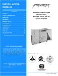
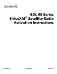
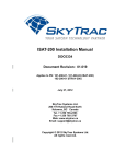
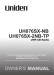
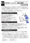
Instructions for Continued Airworthiness
G600, GNS 530W, GNS 430W, GMA 347,
GTX 330D, GMX 200, WSI AV-200
Cessna 208/208B
Dwg. Number:
190-01080-05 Rev. 2
NOTE:
This document supersedes 190-00694-00,
ICA GNS 530W, GMX 200 and WSI AV-200 in Cessna C208/C208B
(from prerequisite STC SA01712SE-D).
NOTE:
This document supersedes 190-00544-50,
Dual GTX330Ds in Cessna 208 Caravan Post Installation Checkout & ICA
(from prerequisite STC SA01512WI-D)
Garmin International, Inc.
1200 E. 151st Street
Olathe, Kansas 66062 USA
Record of Revision
Rev.
Date
Description of Change
1
2
01/25/10
05/21/14
Initial Release
Added maintenance data from prerequisite installations and updated
maintenance data for the G600, GNS 430W/530W, GMX 200, GMA 347,
and GTX 330D Transponders.
TABLE OF CONTENTS
1.
Introduction.......................................................................................................................................... 3
1.1
Purpose ...................................................................................................................................... 3
1.2
Definitions .................................................................................................................................. 3
2. Instructions for Continued Airworthiness ........................................................................................ 4
2.1
Introduction ................................................................................................................................ 4
2.2
Description of Alteration ........................................................................................................... 5
2.3
Control/Operation Information................................................................................................. 7
2.3.1 G600 System......................................................................................................................... 7
2.3.2 GNS 530W/430W ................................................................................................................. 7
2.3.3 GMA 347 ................................................................................................................................ 8
2.3.4 GMX 200 and WSI AV-200 ................................................................................................. 9
2.3.5 GTX 330D .............................................................................................................................. 9
2.4
Servicing Information.............................................................................................................. 10
2.5
Periodic Maintenance Instructions ....................................................................................... 10
2.5.1 GTX 330D Regulatory Testing ......................................................................................... 12
2.5.2 GTX 330D ADS-B Out Testing ......................................................................................... 12
2.5.3 GTX 330D Installation Visual Inspection ........................................................................ 13
2.5.4 GTX 330D Installation Electrical Bonding Test .............................................................. 13
2.6
Troubleshooting Information ................................................................................................. 14
2.7
Removal and Installation Information .................................................................................. 14
2.7.1 GDU 620 .............................................................................................................................. 14
2.7.2 GRS 77................................................................................................................................. 15
2.7.3 GMU 44 ................................................................................................................................ 16
2.7.4 GDC 74A.............................................................................................................................. 17
2.7.5 GAD 43................................................................................................................................. 18
2.7.6 GNS 530W/430W GPS/NAV/COM .................................................................................. 18
2.7.7 GA 35 Antenna ................................................................................................................... 19
2.7.8 GMA 347 Audio Panel ....................................................................................................... 19
2.7.9 GMX 200 .............................................................................................................................. 20
2.7.10
WSI AV-200 and WSI Antenna .................................................................................... 20
2.7.11
GTX 330D........................................................................................................................ 20
2.7.12
Top Transponder Antenna Removal & Replacement ............................................... 21
2.7.13
Bottom Transponder Antenna Removal & Replacement ......................................... 21
2.7.14
Transponder/DME Cable Assembly Removal & Replacement ............................... 22
2.8
Diagrams .................................................................................................................................. 23
2.9
Special Inspection Requirements ......................................................................................... 23
2.9.1 Post-Lightning Strike Inspection....................................................................................... 23
2.9.2 Special Inspection Techniques......................................................................................... 23
2.10 Application of Protective Treatments ................................................................................... 23
2.11 Data Relative to Structural Fasteners .................................................................................. 24
2.12 Special Tools ........................................................................................................................... 24
2.13 Additional Instructions ............................................................................................................ 24
2.14 Overhaul Period ...................................................................................................................... 24
2.15 ICA Revision and Distribution ............................................................................................... 25
2.16 Assistance ................................................................................................................................ 25
2.17 Implementation and Record Keeping .................................................................................. 25
3. Airworthiness Limitations ................................................................................................................ 25
Appendix A. Transponder/DME Cable Connector Removal & Replacement.............................. 26
A.1
Transponder Cable Connectors ........................................................................................... 26
A.2
DME Cable Connectors ......................................................................................................... 28
Instructions for Continued Airworthiness G600, GNS 530W, GNS 430W,
GMA 347, GTX 330D, GMX 200, WSI AV-200 Cessna 208/208B
190-01080-05 Rev. 2
Page 2 of 29
1. Introduction
1.1
Purpose
This document is designed for use by the installing agency as Instructions for Continued Airworthiness in
response to 14 CFR § 23.1529, and Part 23 Appendix G.
This ICA includes information required by the operator to adequately maintain the Garmin G600 Avionics
Display System, Garmin GNS 530W GPS/NAV/COM, Garmin GNS 430W GPS/NAV/COM, Garmin GA
35 GPS Antennas, Garmin GMA 347 Audio Panel, Garmin GMX 200, WSI AV-200, Comant CI 1530-1
WSI Antenna, Garmin GTX 330D ES transponders, and Comant CI 105 Transponder Antennas when
installed under the following STCs.
STC Number
Description
SA02017SE-D
Installation of the G600, GNS 430W, GA 35 GPS Antenna, and GMA 347.
(Requires installation of SA01712SE-D and SA01512WI-D as prerequisites)
SA01712SE-D
Installation of the GNS 530W, GA 35 GPS Antenna, GMX 200, WSI AV-200,
and CI 1530-1 WSI Antenna.
SA01512WI-D
Installation of dual GTX 330D ES transponders and CI 105 Transponder
Antennas.
1.2
Definitions
The following terminology is used within this document:
AC:
Advisory Circular
ACO:
Aircraft Certification Office
ADC:
Air Data Computer
AEG:
Aircraft Evaluation Group
AHRS: Attitude Heading Reference System
CFR:
Code of Federal Regulations
FAA:
Federal Aviation Administration
GPS:
Global Positioning System
ICA:
Instructions for Continued Airworthiness
LRU:
Line Replaceable Unit (GTS computer, Antenna, or PA/LNA)
MFD:
Multi-Function Display
OAT:
Outside Air Temperature
PFD:
Primary Flight Display
PMI:
Principal Maintenance Inspector
STC:
Supplemental Type Certificate
TSO:
Technical Standard Order
TVS:
Transient Voltage Suppressor
Instructions for Continued Airworthiness G600, GNS 530W, GNS 430W,
GMA 347, GTX 330D, GMX 200, WSI AV-200 Cessna 208/208B
190-01080-05 Rev. 2
Page 3 of 29
2. Instructions for Continued Airworthiness
2.1
Introduction
Content, Scope,
Purpose and
Arrangement:
Definition of
Abbreviations:
Precautions:
Units of measurement:
STC SA02017SE-D
Maintenance Data
(or later revisions)
STC SA01712SE-D
Maintenance Data
(or later revisions)
STC SA01512WI-D
Maintenance Data
(or later revisions)
Retention:
This document identifies the Instructions for Continued Airworthiness for the
Garmin G600, Garmin GNS 530W, Garmin GNS 430W, Garmin GA 35 GPS
Antennas, Garmin GMA 347, Garmin GMX 200, WSI AV-200, Comant CI 15301 WSI Antenna, Garmin GTX 330D ES transponders, and Comant CI 105
Transponder Antennas installed in a Cessna 208/208B Caravan.
See Definitions in Section 1.2
None
None
• 190-01080-02, General Arrangement, G600 GNS430W GMA347 Cessna
208/208B, Rev. 5
• 190-01080-03, Modification Summary FX, G600 GNS430W GMA347 Cessna
208/208B, Rev. 5 (Sections 4, 5, and Appendix A)
• 190-01080-04, Modification Summary FE, G600 GNS430W GMA347 Cessna
208/208B, Rev. 6 (Sections 4, 5, and Appendix A)
• 190-01080-00, Install Dwg 150, G600 GNS430W GMA347 Cessna
208/208B, Rev. 6
• 190-01080-01, Install Dwg 250, G600 GNS430W GMA347 Cessna
208/208B, Rev. 7
• 005-W0027-00, Installation Wiring FE, G600 GNS430W GMA347 Cessna
208/208B, Rev. 9
• 005-W0027-04, Installation Wiring FX, G600 GNS430W GMA347 Cessna
208/208B, Rev. 7
• 005-00368-12, Avionics Installation, GNS 530(W), GMX200, WSI AV-200,
150, Rev 8
• 005-00368-13, Avionics Installation, GNS 530(W), GMX200, WSI AV-200,
250, Rev 9
• 190-00607-04, GMX 200 Installation Manual, Rev. B
• WSI 305427-00, WSI AV100/AV-200 Installation Manual
• 005-00521-11, GTX330D Antenna Installation in Cessna 208/208B, Rev. 5
• 005-00521-13, DME Antenna Reassignment, Cessna 208/208B, Rev. 6
• 005-00521-14, Avionics Bus 1 Switch/Breaker Modification, Cessna
208/208B, Rev. 2
This document, or the information contained within, will be included in the
aircraft’s permanent records.
Instructions for Continued Airworthiness G600, GNS 530W, GNS 430W,
GMA 347, GTX 330D, GMX 200, WSI AV-200 Cessna 208/208B
190-01080-05 Rev. 2
Page 4 of 29
2.2
Description of Alteration
This STC upgrades existing avionics for the Cessna 208/208B Caravan as summarized below.
Equipment locations are identified in Figure 1 below.
Figure 1 - Equipment Locations (C208B as shown, C208 similar)
G600 System:
The Garmin G600 PFD/MFD System consists of an instrument panel mounted GDU 620 display and
remote mounted LRUs which provide data to the display. The GDU 620 provides controls for the G600
system and a PFD and MFD in the pilot’s primary field of view. The remote mounted LRUs include dual
GRS 77 AHRS, dual GMU 44 Magnetometers, one GDC 74A ADC, one GTP 59 OAT probe and one
GAD 43 Adapter.
The GDU 620 MFD displays weather radar information and provides status/control of the Aircraft Data
Acquisition System Plus (ADAS+) engine trend monitor system.
Instructions for Continued Airworthiness G600, GNS 530W, GNS 430W,
GMA 347, GTX 330D, GMX 200, WSI AV-200 Cessna 208/208B
190-01080-05 Rev. 2
Page 5 of 29
GNS 530W and GNS 430W GPS/NAV/COM:
The Garmin GNS 530W and GNS 430W GPS/NAV/COM units are located in the radio stack in the center
instrument panel and combines controls, a multi-function display, NAV and COM transceivers and a
GPS/WAAS navigator into each unit. Data from the GNS 530W and GNS 430W are displayed on the
GDU 620. The GNS 530W and GNS 430W installations includes two GA 35 antennas, one for each GNS
unit. The GNS 530W and GNS 430W are connected to previously installed Nav and Com antennas.
GMA 347 Audio Panel:
The Garmin GMA 347 Audio Panel is a horizontally oriented panel-mounted audio control panel, marker
beacon system, and intercom, which interfaces to external inputs. The GMA 347 is connected to a
previously installed marker beacon antenna. A GMA 347 maintenance connector (PG11) is installed
behind the pilot’s instrument panel for connection when performing configuration or software updates.
GMX 200 Multifunction Display and WSI AV-200:
The Garmin GMX 200 multifunction display is located in the radio stack in the center instrument panel
displaying information from the GNS 530W, WSI AV-200 weather datalink receiver, and airborne weather
radar (RDR 2000 radars only).
A remote mounted WSI AV-200 with Comant CI 1530-1 (WSI Low Profile Satellite Antenna) is installed
and provides datalink weather information to the GMX 200 multifunction display.
GTX 330D ES Transponders:
Two Garmin GTX330D ES Mode S diversity transponders with ADS-B Out are installed in the radio stack
in the center instrument panel. Four Comant CI 105 L-Band antennas are also installed. Two antennas
are required for each GTX330D; one mounted on the top and the other on the bottom of the aircraft, for a
total of four antennas for the installation. Only one GTX330D can be active at a time. A XPDR 1/2 select
switch allows the crew to toggle between GTX330D #1 and #2. The switch state determines which
GTX330D is the active transponder. Transponder maintenance connectors are installed below the
instrument panel for easy connection when performing software updates.
The GNS 530W and GNS 430W outputs GPS data, including GPS groundspeed, altitude, latitude,
longitude, track, and position integrity, to both GTX330D transponders over an RS-232 serial data bus.
The GTX330D only transmits ADS-B messages and cannot receive and process ADS-B messages.
Avionics Bus 1 Switch/Breaker Modification:
On Caravan aircraft equipped with KFC250 autopilots, the Avionics Bus 1 switch/breaker is required to be
upgraded from the existing 20 amp unit to a new 30 amp unit. This upgrade is optional for KFC150equipped Caravans, to be used for installations which require additional electrical margin.
DME Antenna Re-assignment:
The existing transponder #2 antenna location on pre-modification aircraft is located on the cargo pod aft
left side. This antenna remains installed and becomes the DME antenna. The two forward-most L-Band
antennas under the cargo pod are replaced with new Comant CI105s and become transponder #1 (left
side) and transponder #2 (right side) antennas respectively. A new low-loss DME coaxial cable is also
installed.
Instructions for Continued Airworthiness G600, GNS 530W, GNS 430W,
GMA 347, GTX 330D, GMX 200, WSI AV-200 Cessna 208/208B
190-01080-05 Rev. 2
Page 6 of 29
2.3
Control/Operation Information
2.3.1 G600 System
The GDU 620, GRS 77, GMU 44, and GDC 74A are powered by Main Bus 2 which is normally energized
with battery, generator, or external power applied to the aircraft. The GAD 43 is powered by Avionics Bus
1 which is normally controlled by the Avionics Bus 1 master switch. The LRUs do not have individual
power switches and are powered when the bus is energized and the circuit breakers are closed. The
following circuit breakers provide power to the individual LRUs:
• PFD: GDU 620
• AHRS 1: GRS 77 #1 and GMU 44 #1
• AHRS 2: GRS 77 #2 and GMU 44 #2
• ADC: GDC 74A
• GAD: GAD 43
The GDU 620 has a PFD (left) and MFD (right) display and front panel controls for performing all G600
normal and configuration operations. Knobs at the lower left and right corners are used for selecting and
entering data on each screen. The function of the soft keys along the bottom of the display is depicted by
the text above the key. There are dedicated ENT, CLR, and MENU keys on the right side of the unit.
Turning the PFD knob adjusts the values for the mode selected by the PFD bezel keys, such as, Heading
(HDG), Course (CRS), Altitude (ALT), Vertical Speed (V/S), and Barometric Setting (BARO). The values
are shown in a window to the left of the HSI. Pressing the PFD knob reverts to the default value of the
selected mode.
The Small (Inner) MFD Knob selects a specific page within a page group. Pressing the small MFD knob
turns the selection cursor ON and OFF. When the cursor is ON, data may be entered in the applicable
window by turning the small and large MFD knobs. In this case, the large MFD knob moves the cursor on
the page and the small MFD knob selects individual characters or values for the highlighted cursor
location. The Large (Outer) MFD Knob selects the MFD page group. When the cursor is ON, the large
MFD knob moves the cursor to highlight available fields.
The G600 system starts in normal mode when power is applied to the LRUs. After completing the selftest, the database confirmation page is displayed. Invalid or expired databases are displayed in yellow.
Press ENT to proceed to normal mode. Normal mode consists of a Primary Flight Display (PFD) on the
left screen and a Multifunction Display (MFD) on the right screen. The AHRS alignment should complete
within one minute and attitude should be displayed on the PFD. System alerts are accessible via an
“ALERTS” softkey at the lower right of the MFD. During normal system operation with all aircraft systems
and avionics powered there should not be any red Xs or system alerts on the GDU 620.
To enter into Configuration Mode for the G600 system, verify that the GDU 620 is off and the Installer
Unlock Card, P/N 010-00769-60 is installed in the bottom card slot of the GDU 620. Apply power to the
GDU 620 while holding the ENT key. Release the ENT key when “INITIALIZING SYSTEM” appears in
the upper left corner of the display.
Refer to the appropriate Modification Summary, Section 4, for further Configuration instructions.
2.3.2 GNS 530W/430W
GNS 530W: The GNS 530W is powered by Avionics Bus 1 which is normally controlled by the Avionics
Bus 1 master switch. The GNS 530W also contains a power switch which is controlled by the COM
volume rotary knob near the upper left corner. COM 1 and NAV 1 circuit breakers on Avionics Bus 1
supply power to the GNS 530W.
GNS 430W: The GNS 430W is powered by Avionics Bus 2 which is normally controlled by the Avionics
Bus 2 master switch. The GNS 430W also contains a power switch which is controlled by the COM
Instructions for Continued Airworthiness G600, GNS 530W, GNS 430W,
GMA 347, GTX 330D, GMX 200, WSI AV-200 Cessna 208/208B
190-01080-05 Rev. 2
Page 7 of 29
volume rotary knob near the upper left corner. COM 2 and NAV 2 circuit breakers on Avionics Bus 2
supply power to the GNS 430W.
NOTE:
The following operating instructions are applicable
to both the GNS 530W and GNS 430W
The GNS is self-contained with a single display and front panel controls. COM and NAV volume is
controlled via two small rotary knobs. COM/NAV frequency selection is controlled via the left dualconcentric knobs. Pressing the knob toggles between COM and NAV frequency selection. There are
individual COM and NAV frequency flip-flop keys near the volume knobs.
The right dual-concentric knobs are used for page selection and entering data. The Small (Inner) knob
selects a specific page within a page group. Pressing the small knob turns the selection cursor ON and
OFF. When the cursor is ON, data may be entered in the applicable window by turning the small and
large knobs. In this case, the large knob moves the cursor on the page and the small knob selects
individual characters or values for the highlighted cursor location. The Large (Outer) Knob selects the
page group. When the cursor is ON, the large knob moves the cursor to highlight available fields.
There are dedicated ENT, CLR, and MENU keys on the right side of the unit. System messages are
viewable by pressing the MSG key at the bottom of the unit.
The GNS starts in normal mode when power is applied to the unit and the power switch is on. After
completing the self-test, the database confirmation page is displayed. Invalid or expired databases are
displayed in yellow. Press ENT to proceed to the INSTRUMENT PANEL SELF-TEST page. CDI/HSI
indications may be verified while this page is displayed. Press ENT to continue to satellite acquisition.
After a GPS position has been acquired, the unit will be ready for operation. During normal system
operation with all aircraft systems and avionics powered there should not be any system messages
displayed.
To enter into Configuration Mode for the GNS GPS/NAV/COM unit, verify the unit turned off. Apply power
to the GNS while holding the ENT key. Release the ENT key when “INITIALIZING SYSTEM” appears in
the upper left corner of the display.
Refer to the appropriate Modification Summary, Section 4, for further Configuration instructions.
2.3.3 GMA 347
The GMA 347 is powered by Avionics Bus 2 which is normally controlled by the Avionics Bus 2 master
switch. The GMA 347 also contains a power switch which is controlled by the Pilot’s volume rotary knob
near the left side of the unit. An AUD/MKR circuit breaker on Avionics Bus 2 supplies power to the GMA
347.
The GMA 347 is self-contained with front panel controls. Audio source selection is controlled by the top
row of buttons with green LEDs indicating selected sources. COM MIC selection buttons are on the
bottom row with a green LED indicating the selected COM MIC. The left dual concentric knob controls
pilot intercom volume and squelch. The right dual concentric knob controls copilot intercom volume and
squelch.
The GMA 347 starts in normal mode when power is applied to the unit and the power switch is on. All
lights will momentarily illuminate during the power-on self test.
Follow these steps to enter the GMA 347 Audio Panel into Configuration Mode:
1. Ensure the GMA 347 is powered off.
2. Locate connector PG11 which breaks out near connector PA28 underneath the pilot instrument
panel above the rudder pedals.
3. Plug 3-pin connector from GMA347 programming cable into PG11; plug other end into your
computer serial port.
Instructions for Continued Airworthiness G600, GNS 530W, GNS 430W,
GMA 347, GTX 330D, GMX 200, WSI AV-200 Cessna 208/208B
190-01080-05 Rev. 2
Page 8 of 29
4. Start the GMA Configuration tool, GMA_CONFIG.EXE (Garmin P/N 006-A0115-00), on your
computer.
5. Power up the GMA 347.
Refer to the appropriate Modification Summary, Section 4, for further Configuration instructions.
2.3.4 GMX 200 and WSI AV-200
To enter configuration mode on the GMX 200, immediately after the self-test is complete press line select
keys 1, 4, and 6 in sequence before pressing any other keys (where 1 is the top line select key, 4 is the
fourth key down, and 6 is the lower most line select key).
Refer to the appropriate Modification Summary, Section 4, for further Configuration instructions.
2.3.5 GTX 330D
The #1 GTX330D receives power from Avionics Bus 1, and the #2 GTX330D receives power from
Avionics Bus 2.
The GTX 330D starts in normal mode when power is applied to the unit. To enter configuration mode
apply power to the GTX 330D while holding the FUNC key, then press the ON key to access the
configuration pages.
In order to perform maintenance tasks such as software updates and other diagnostic activities, a
Windows-compatible PC computer (preferably a laptop) is required. The maintenance port is located
below the instrument panel just immediately behind the throttle quadrant as shown in 190-01080-00,
Install Dwg 150, G600 GNS430W GMA347 Cessna 208/208B and 190-01080-01, Install Dwg 250, G600
GNS430W GMA347 Cessna 208/208B.
CAUTION:
The GNS 430W must be powered off prior to
programming transponders via the maintenance port.
Refer to the appropriate Modification Summary, Section 4, for further Configuration instructions.
Instructions for Continued Airworthiness G600, GNS 530W, GNS 430W,
GMA 347, GTX 330D, GMX 200, WSI AV-200 Cessna 208/208B
190-01080-05 Rev. 2
Page 9 of 29
2.4
Servicing Information
In the event of a G600 system, GNS 530W, GNS 430W, GMA 347, or GTX 330D failure, troubleshoot the
unit(s) in accordance with Appendix A of the appropriate Modification Summary. In the event of a GMX
200 or WSI AV-200 failure, troubleshoot the unit(s) in accordance with the Installation Manual for that
unit. The Garmin GA 35 GPS Antennas, Comant CI 105 Transponder Antennas, and Comant CI 1530-1
WSI Antenna are non-repairable; in the event of a failure, the antenna must be replaced.
2.5
Periodic Maintenance Instructions
Maintenance of the components installed by this STC is on condition, except as noted in the following
table.
Item
GRS 77 AHRS
GDC 74A ADC
GA 35 GPS
Antennas,
CI 1530-1 WSI
Antenna
GDU 620,
GRS 77,
GDC 74A,
GMU 44,
GTP 59,
GAD 43,
GNS 530W,
GNS 430W,
GMA 347
Description/Procedure
Interval
The GRS 77 utilizes an Earth magnetic field model which is
updated approximately every five years as part of the Aviation
Database maintained by the owner/operator. If the magnetic
model is not current, the unit will issue an alert upon startup
indicating the model has expired. The model can be updated by
inserting an aviation database card in the GDU 620 with an
updated IGRF model and powering on the system. A prompt will
direct the user to press ENT to update the model.
Test according to 14 CFR Part 91.411 and Part 43 Appendix E.
See the pitot-static checkout procedure in Section 5 of the
appropriate modification summary document.
The tests of Part 43 Appendix E sub-paragraphs (iv)
(Friction) and (vi) (Barometric Scale Error) are not
applicable because the digital outputs of the GDC 74A are
not susceptible to these types of errors.
On condition
24 Calendar
Months
Conduct a visual inspection of the antennas and their mounting.
Verify there are no cracks on the antenna, no cracks or
deformation in the mounting structure around the antenna, and
that all sealing fillets around the antennas are in good condition.
If the antenna is broken, cracked, or dented it must be replaced.
If the attachment is not secure, or the antenna seal shows signs
of damage or decomposition re-attach antenna as described in
section 2.7.7.2 (GA 35 antenna) or section 2.7.10.2 (WSI
antenna).
Conduct a visual inspection (look for signs of wear, deterioration,
or damage to wires, backshells, or connectors) on units and their
wire harnesses to ensure installation integrity:
1. Gain access to LRU (see General Arrangement Drawing
for LRU locations)
2. Inspect each unit for security of attachment.
3. Inspect all knobs and buttons for legibility.
4. Inspect condition of wiring, routing and
attachment/clamping.
5. Inspect integrity of shield terminations.
6. Inspect for signs of corrosion on equipment and rack
installations.
Instructions for Continued Airworthiness G600, GNS 530W, GNS 430W,
GMA 347, GTX 330D, GMX 200, WSI AV-200 Cessna 208/208B
12 Calendar
Months [1]
12 Calendar
Months [1]
190-01080-05 Rev. 2
Page 10 of 29
Item
GDU 620,
GRS 77,
GDC 74A,
GMU 44,
GTP 59,
GAD 43,
GNS 530W
GNS 430W,
GMA 347
Description/Procedure
Interval
Perform an electrical bonding test for each listed LRU:
1. Gain access to the LRU (see General Arrangement
Drawing for LRU location)
2. Disconnect all harness/antenna connectors from the LRU
3. Measure the resistance between the LRU and a nearby
exposed portion of aircraft metallic structure
a. For the GDU 620, verify the resistance is less
than or equal to 40 milliohms
b. For the GTP 59, verify the resistance is less than
or equal to 5 milliohms
c. For the remaining LRUs, verify the resistance is
less than or equal to 20 milliohms
d. If the resistance is higher than values listed
above, remove LRU, clean bonding interfaces,
reinstall, and re-measure until half the resistance
listed above or less is reached.
4. Reconnect all disconnected harness/antenna connectors
and ensure they are secure
Every 2000
flight hours or
ten (10) years,
whichever is
first
Repeat for each listed LRU.
GA 35 GPS
Antennas
An electrical bonding test must be performed on the GA 35
Antennas.
For first GA 35 Antenna:
1. Gain access to the antenna (see General Arrangement
Drawing for location).
2. Disconnect the coaxial cable from the antenna connector.
3. Measure the resistance between the antenna base
connector and a nearby exposed portion of aircraft
structure (example: exposed rivet on fuselage stringer).
4. Verify the resistance is equal to or less than 5 milliohms.
5. Reconnect the coaxial cable to the antenna connector and
ensure it is secured.
Every 2000
flight hours or
ten (10) years,
whichever is
first
Repeat for second GA 35 Antenna.
In the event of bonding test failure, remove antenna, clean and
re-attach using the procedures in Section 2.7.7.
GTX 330D
Regulatory Testing
The GTX 330D transponders must be tested and shown to
comply with 14 CFR Part 91.411, 91.413 and Part 43 Appendix E
and F as described in section 2.5.1.
24 Calendar
Months
GTX 330D
ADS-B Out Testing
The GTX 330D transponders must be shown to comply with 14
CFR Part 91.227 as described in section 2.5.2.
Replacement of
GNS 530W or
GNS 430W
GTX 330D, and
CI 105 Antennas
A visual inspection of the GTX 330D transponders and CI 105
antennas must be performed as described in section 2.5.3.
12 Calendar
Months [1]
An electrical bonding test of the GTX 330D transponders and CI
105 antennas must be performed as described in section 2.5.4.
Every 2000
flight hours or
ten (10) years,
whichever is
first
GTX 330D, and
CI 105 Antennas
Notes: [1] Complete within the preceding 12 calendar months as part of an annual or progressive
inspection program. This inspection interval may be extended to within the preceding 24 calendar months
for aircraft that are inspected in accordance with other approved aircraft inspection programs.
Instructions for Continued Airworthiness G600, GNS 530W, GNS 430W,
GMA 347, GTX 330D, GMX 200, WSI AV-200 Cessna 208/208B
190-01080-05 Rev. 2
Page 11 of 29
2.5.1 GTX 330D Regulatory Testing
With the transponders operating in normal mode, the following regulatory tests are required to be
performed:
• Altitude Reporting Equipment Tests in accordance with 14 CFR Part 91.411 and Part 43
Appendix E
• ATC Transponder Tests and Inspections in accordance with 14 CFR Part 91.413 and Part 43
Appendix F
These regulatory tests require the use of a Mode S transponder ramp tester. Specific instructions for
operating the ramp tester are contained in the applicable operator's manual.
Diversity Isolation Testing
To satisfy the requirement for Part 43 Appendix F subparagraph (e), transponder diversity isolation must
be verified. To successfully test diversity isolation, the installer must take the following action:
1. Remove power from the ADC, GNS 530W, and GNS 430W for the duration of the diversity isolation
test.
2. Cycle power to the GTX 330D and enter configuration mode.
3. On the ADS-B TX Page, select Pilot Set for ADS-B TX.
4. Cycle power to the GTX 330D and allow the unit to initialize normally.
5. Place the GTX 330D in ‘ground’ operating mode by pressing and holding the STBY key until the
operating mode changes to ‘GND’. At this point the technician should confirm the transponder’s
Mode S airborne state is ‘AIR’ by observing the ramp tester.
6. Temporarily disable the ADS-B Extended Squitter function on each GTX 330D by pressing the
FUNC key until the ADS-B TX page is displayed, then toggle the ADS-TX function off using the
START/STOP key.
7. The diversity isolation test may now be conducted. Note that it is critical to isolate the antenna
under test from the antenna not being tested to achieve passing results of ≥20 dB isolation. Use
proper testing practices and follow the test equipment manufacturer’s recommendations. It is
recommended that an antenna isolating device be utilized for this test.
8. After completing tests on all four transponder antennas, the ADC, GNS 530W, and GNS 430W
may be powered back on and the ADS-B TX function re-enabled.
9. If desired, power cycle the GTX 330D and enter configuration mode. On the ADS-B TX Page,
select Enabled for the ADS-B TX setting.
2.5.2 GTX 330D ADS-B Out Testing
Perform the following procedure any time either GPS position source is replaced/modified. The test is
performed using a transponder ramp test set, such as the Aeroflex IFR-6000 or TIC TR-220 (Note: S/W
v5.30 or later is required on the TR-220). For instructions on operating the ramp tester, refer to the
manufacturer’s documentation.
1. Ensure the aircraft is in a location where a GPS signal can be received (e.g. outdoors with a clear
view of the sky).
2. Power on the aircraft/avionics and ensure that both transponders are powered on.
3. If the transponders are configured for pilot control of the ADS-B transmitter, press the FUNC key
until “ADS-B TX” is displayed and ensure that ADS-B TX is “ON” for both transponders (press the
START/STOP key to toggle between ON and OFF).
4. Select XPDR 1 using the transponder selector switch.
5. Remove power from the GNS 430W by pulling the NAV 2 circuit breaker. Ensure the GNS 530W
is operating normally and has acquired a GPS position.
6. Temporarily configure XPDR 1 into “airborne” mode as follows:
a. Start XPDR 1 in configuration mode (hold the OFF key to power down the unit, then hold
the FUNC key and press the ON key).
b. Press the FUNC key until the “SQUAT SWITCH?” page is displayed. Then use the
CRSR and 8/9 keys to change the setting to “YES” and the “SENSE” to “LOW. “ Press
the CRSR key until no fields are highlighted to save the changes.
7. Restart XPDR 1 in normal operating mode and select ALT mode.
8. Using the transponder test set, verify the following ADS-B Out parameters are being transmitted:
• NACv value of 1 or greater
Instructions for Continued Airworthiness G600, GNS 530W, GNS 430W,
GMA 347, GTX 330D, GMX 200, WSI AV-200 Cessna 208/208B
190-01080-05 Rev. 2
Page 12 of 29
9.
10.
11.
12.
13.
14.
15.
• SDA value of 2 (≤ 1x10⁻⁵)
• SIL value of 3 (≤ 1 x10⁻⁷)
• NACp value of 8 or greater
• NIC value of 7 or greater
Reset the XPDR 1 squat switch configuration as follows:
a. Start XPDR 1 in configuration mode (hold the OFF key to power down the unit, then hold
the FUNC key and press the ON key).
b. Press the FUNC key until the “SQUAT SWITCH?” page is displayed. Then use the
CRSR and 8/9 keys to change the setting to “NO.” Press the CRSR key until no fields
are highlighted to save the changes.
Restart XPDR 1 in normal operating mode and select ALT mode.
Using the transponder test set, verify XPDR 1 is in the “on ground” state. This may be
accomplished by one of the following methods:
a. Verifying the length or width ADS-B Out parameter is being transmitted, or
b. Verifying the Mode S air/ground status is “on ground.”
Select XPDR 2 using the transponder selector switch.
Apply power to the GNS 430W by resetting the NAV 2 circuit breaker. Remove power from the
GNS 530W by pulling the NAV 1 circuit breaker. Ensure the GNS 430W is operating normally
and has acquired a GPS position.
Repeat steps 6 though 11 on XPDR 2. Note: references to XPDR 1 in these steps now refer to
XPDR 2.
The test is complete. Reset the NAV 1 circuit breaker and select STBY mode on the transponder
2.5.3 GTX 330D Installation Visual Inspection
Conduct a visual inspection of the GTX 330D installation in the following locations:
1. Inspect all GTX 330D knobs and buttons for legibility of labels and markings.
2. Inspect GTX 330D units for security of attachment.
3. Inspect mounting rack and hardware for integrity.
a. Verify the racks, fasteners, and support structure are in good condition and are securely
fastened.
4. Inspect the condition of the wiring harnesses and coaxial cables.
a. Verify that all wiring and cables are securely fastened.
b. Verify that the harness shows no signs of cracking, chaffing, abrasion, melting, or any
other form of damage.
5. Cargo Pod Interior: Inspect both lower transponder antenna locations (remove Isocryl tape
sealant from antenna stud holes in cargo pod):
a. Verify the antenna and ground plane fasteners are secure.
b. Verify no moisture or corrosion is present.
c. Verify no visible delaminating of composite structure exists.
d. Replace flexible Isocryl tape sealant into all antenna stud holes in accordance with the
Antenna Installation drawing, 005-00521-11.
6. Fuselage Top: Inspect the exterior top transponder antenna installations (Diversity Systems only)
a. Verify the antennas are securely fastened.
b. Verify the sealant around each antenna base is in good condition.
c. Verify there is no evidence of cracking or corrosion at the installation site.
7. Cargo Pod Exterior: Inspect the bottom exterior transponder antenna installations:
a. Verify the antennas are securely fastened.
b. Verify the sealant around each antenna base is in good condition.
c. Verify the antenna ground plane is securely attached to the cargo pod structure and that
there are no signs of de-lamination or looseness.
d. Verify there is no evidence of cracking or corrosion at the installation site.
2.5.4 GTX 330D Installation Electrical Bonding Test
Perform an equipment electrical bonding check. All electrical bonding for this installation must be 5
milliohms DC resistance or less. If the resistance is higher than 5 milliohms, remove LRU, clean bonding
interfaces, reinstall, and re-measure until 2.5 milliohms or less is reached.
GTX330D Unit Racks and Connectors:
Instructions for Continued Airworthiness G600, GNS 530W, GNS 430W,
GMA 347, GTX 330D, GMX 200, WSI AV-200 Cessna 208/208B
190-01080-05 Rev. 2
Page 13 of 29
1. Disconnect all harness/antenna connectors from the LRU.
2. From behind the instrument panel, measure the resistance from each of the GTX330D racks to a
nearby aircraft primary metallic structure. Verify the resistance is equal to or less than 5
milliohms.
3. From behind the instrument panel, measure the resistance from each GTX330D connector to a
nearby aircraft primary metallic structure. Verify the resistance is equal to or less than 5
milliohms.
4. Reconnect all disconnected harness/antenna connectors and ensure they are secure.
Top Antennas:
1. Gain access to the upper antenna installation site by removing the interior cargo liner (refer to the
Cessna 208 Maintenance Manual, D2078-21-13).
2. Measure the resistance between the base studs of each antenna to an exposed portion of aircraft
structure.
3. Verify the resistance is equal to or less than 5 milliohms.
4. Reinstall the interior cargo liner in accordance with the Cessna 208 Maintenance Manual.
Bottom Antennas:
1. Gain access to the lower antenna installation site within the cargo pod.
2. Remove the Isocryl tape sealant from within the antenna stud holes in the cargo pod.
3. Measure the resistance between the base studs of each antenna to an exposed portion of aircraft
structure (example: exposed rivet on cargo pod former).
4. Verify the resistance is equal to or less than 5 milliohms.
5. Reinstall the Isocryl tape sealant in accordance with the Antenna Installation Drawing, 00500521-11.
2.6
Troubleshooting Information
Refer to Appendix A of the appropriate Modification Summary for troubleshooting procedures for any of
the LRUs of the G600 system, GNS 530W, GNS 430W, GMA 347, and/or GTX 330D units. For the GMX
200 and/or the WSI AV-200 troubleshoot the unit(s) in accordance with the Installation Manual for that
unit listed in section 2.1 of this document.
2.7
Removal and Installation Information
2.7.1 GDU 620
2.7.1.1 Removal
1.
2.
3.
4.
Remove the six mounting screws from the bezel of the GDU 620.
Pull the GDU 620 far enough out from the instrument panel to access the three rear connectors.
Disconnect the rear connectors.
Remove the GDU 620.
2.7.1.2 Installation
1. Visually inspect the connectors to ensure that there are no bent or damaged pins. Repair any
damage.
2. Connect the rear connectors, ensuring that each slidelock is secured on both sides.
Set the GDU 620 into place.
3. Install the six mounting screws into the bezel of the GDU 620.
NOTE
The installation configuration settings are stored in the configuration module and will be
retained when the GDU 620 is replaced with a new unit. User settings, such as map
orientation preferences, are stored internally and will be lost when the GDU 620 is
replaced with a new unit.
Instructions for Continued Airworthiness G600, GNS 530W, GNS 430W,
GMA 347, GTX 330D, GMX 200, WSI AV-200 Cessna 208/208B
190-01080-05 Rev. 2
Page 14 of 29
Original GDU 620 is Reinstalled
If the original GDU 620 is reinstalled, then no software loading is required. This does not include
units that were returned for repair as their software and configuration files are deleted during the
repair testing process. No configuration is required.
New, Repaired or Exchanged GDU 620 is Installed
If the GDU 620 is replaced with a new, repaired, or exchange unit, then software must be loaded. No
configuration is required.
NOTE
Upon first power-up after installing a new GDU 620, it is normal to see a series of
“LOADING…” messages appear on the screen. These messages indicate that the
GDU 620 is updating its configuration settings from the configuration module.
Continue to the GDU 620 Software Loading procedure, followed by the Manifest Configuration and
the Configuration Module Update, located in Section 4 of the appropriate Modification Summary.
GDU 620 Configuration Module is Replaced
If the GDU 620 Configuration Module is replaced, the GDU 620 will update the configuration module
from its internally-stored settings when the UPDT CFG soft key is pressed. If the GDU 620 is
replaced at the same time as the Configuration Module, then the System Setup will need to be
performed. Refer to Section 4 of the appropriate Modification Summary for more information.
2.7.1.3 Return to Service
After removing and reinstalling the GDU 620 per the instructions above, a simple return-to-service check
should be performed.
1. Power up the GDU 620 and all interfaced systems in normal mode.
2. Verify that there are no red-Xs and that no alerts are present. If red Xs or alerts are present,
troubleshoot using Appendix A of the appropriate Modification Summary.
2.7.2 GRS 77
2.7.2.1 Removal
1.
2.
3.
4.
Gain access to GRS 77 (See General Arrangement Drawing for location)
Disconnect the GRS 77 connector.
Loosen the four Phillips thumbscrews with a screwdriver.
Gently lift the GRS 77 from the mounting plate (if the supports for the mounting plate are
removed, the GRS 77 must be recalibrated).
2.7.2.2 Installation
1. Place the GRS 77 on the mounting plate, ensuring the orientation is correct.
2. Fasten the unit to the plate using the Phillips thumbscrews. Recommended torque is 22-25 inch
pounds.
3. Visually inspect the connectors to ensure there are no bent or damaged pins. Repair any
damage.
4. Connect the connector to the GRS 77, ensuring that each slidelock is secured on both sides.
Original GRS 77 is Reinstalled
If the original GRS 77 is reinstalled, then no software loading is required. This does not include units
that were returned for repair as their software and configuration files are deleted during the repair
testing process. Reference Table 2-1 to determine whether recalibration is required.
New, Repaired or Exchange GRS 77 is Installed
Instructions for Continued Airworthiness G600, GNS 530W, GNS 430W,
GMA 347, GTX 330D, GMX 200, WSI AV-200 Cessna 208/208B
190-01080-05 Rev. 2
Page 15 of 29
If the GRS 77 is replaced with a new, repaired, or exchange unit, then software must be loaded per
Section 4 of the appropriate Modification Summary. Reference Table 2-1 to determine whether recalibration is required.
GRS 77 Configuration Module is Replaced
If the GRS 77 Configuration Module is replaced, the GRS 77 must be re-calibrated. Reference Table
2-1.
2.7.2.3 Return to Service
After removing and reinstalling the GRS 77, the following return-to-service checks should be performed.
1. Power up the G600 system with the GDU 620 in normal mode.
2. Verify that the GDU displays valid heading and attitude within approximately one minute.
NOTE
The Heading can remain invalid if the magnetometer is near a large metal structure such as a hangar
wall or if the magnetometer is close to a large ground power cart.
3. Verify that no unexpected alerts are present. If alerts are present, troubleshoot using Appendix A
of the appropriate Modification Summary.
Table 2-1. GRS 77 Calibration Criteria
Calibrations Required
GRS 77
GRS/GMU
Engine Run-up
Pitch/Roll
Magnetic
Vibration
Condition
Offset
Calibration
Test
See Section 4 of
See Section 4 of
See Section 4 of
Modification
Modification
Modification
Summary
Summary
Summary
GRS 77 AHRS was removed and/or
replaced. The mounting tray was NOT
None Required.
removed and the mounting tray bolts
were NOT loosened.
GRS 77 AHRS was removed and/or
replaced. The mounting tray WAS
removed and/or mounting tray bolts
X
X
X
WERE loosened.
GRS 77 AHRS Configuration Module
X
X
X
was replaced.
2.7.3 GMU 44
2.7.3.1 Removal
1.
2.
3.
4.
Gain access to the GMU 44 magnetometer (see General Arrangement Drawing for location).
Unscrew the three screws that hold the GMU 44 to its mounting rack.
Carefully lift the GMU 44 from the rack.
Disconnect the wiring harness.
2.7.3.2 Installation
1. Visually inspect the connectors to ensure there are no bent or damaged pins. Repair any
damage.
2. Connect the wiring harness to the GMU 44.
3. Lower the GMU 44 into the rack and secure the plate with the three Phillips screws.
Original GMU 44 is Reinstalled
If the original GMU 44 was reinstalled, then software loading is not required. This does not include
units that were returned for repair as their software and configuration files are deleted during the
repair testing process. Recalibration is only required if the mount for the magnetometer was
Instructions for Continued Airworthiness G600, GNS 530W, GNS 430W,
GMA 347, GTX 330D, GMX 200, WSI AV-200 Cessna 208/208B
190-01080-05 Rev. 2
Page 16 of 29
changed. If the magnetometer mount was changed, refer to Section 4 of the appropriate Modification
Summary for the GRS 77/GMU 44 Magnetic Calibration.
New, Repaired or Exchange GMU 44 is Installed
If the GMU 44 was replaced with a new, repaired, or exchanged unit, then software must be loaded
and the GRS 77/GMU 44 Magnetic Calibration must be performed. Refer to Section 4 of the
appropriate Modification Summary for more information for instructions on loading software and
Magnetic Calibration.
2.7.3.3 Return to Service
After removing and reinstalling the GMU 44, the following return-to-service checks should be performed.
1. Power up the G600 system with the GDU 620 in normal mode.
2. Verify that the GDU displays valid heading within approximately one minute.
NOTE
The heading can remain invalid if the magnetometer is near a large metal structure such as a hangar
wall or if the magnetometer is close to a large ground power cart.
3. Verify that no unexpected alerts are present. If alerts are present, troubleshoot using Appendix A
of the appropriate Modification Summary.
2.7.4 GDC 74A
2.7.4.1 Removal
1.
2.
3.
4.
Gain access to the GDC 74A (see General Arrangement Drawing for location)
Disconnect the pitot/static plumbing from the rear of the unit. Disconnect the single connector.
Loosen each thumbscrew on the hold-down clamp and remove the clamp.
Carefully remove the unit from its mount.
2.7.4.2 Installation
1.
2.
3.
4.
Place the unit in the mounting tray.
Position the locking clamp and fasten using the thumbscrews.
Connect the pitot/static plumbing.
Inspect the connector and pins for damage. Repair any damage.
5. Connect the connector to the unit, ensuring that each slidelock is secured on both sides.
Original GDC 74A is Reinstalled
If the original GDC 74A is re-installed, then no software loading is required. This does not include
units that were returned for repair as their software and configuration files are deleted during the
repair testing process.
New GDC 74A is Installed
If the GDC 74A is replaced with a new, repaired, or exchange unit, then software must be loaded to
the unit. Refer to Section 4 of the appropriate Modification Summary for more information.
GDC 74A Configuration Module is Replaced
If the GDC 74A Configuration Module is replaced, the GDC 74A must be configured. Refer to Section
4 of the appropriate Modification Summary for more information.
2.7.4.3 Return to Service
After removing and reinstalling the GDC 74A, the following return-to-service checks should be performed.
1. Power up the G600 system with the GDU 620 in normal mode.
2. Verify that the GDU displays valid air data within approximately one minute.
3. Verify that no unexpected alerts are present. If alerts are present, troubleshoot using Appendix A
of the appropriate Modification Summary.
Instructions for Continued Airworthiness G600, GNS 530W, GNS 430W,
GMA 347, GTX 330D, GMX 200, WSI AV-200 Cessna 208/208B
190-01080-05 Rev. 2
Page 17 of 29
4. Perform a leak check of the pitot-static system and observe the airspeed, altitude, and vertical
speed for proper operation.
2.7.5 GAD 43
2.7.5.1 Removal
1.
2.
3.
4.
Gain access to the GAD 43 (see General Arrangement Drawing for location)
Disconnect the GAD 43 connector.
Remove the six mounting screws.
Carefully remove the unit.
2.7.5.2 Installation
1. Place the GAD 43 in its mounting location and align its mounting holes with the nutplates beneath
it.
2. Insert the six mounting screws and tighten the screws to hold the GAD 43 in place.
3. Inspect the connector and pins for damage. Repair any damage.
4. Connect the connector to the unit, ensuring that each slidelock is secured on both sides.
Original GAD 43 is Reinstalled
If the original GAD 43 is re-installed, then no software loading or configuration is required. This does
not include units that were returned for repair as their software and configuration files are deleted
during the repair testing process.
New GAD 43 is Installed
If the GAD 43 is replaced with a new, repaired, or exchange unit, then software must be loaded to the
unit and the configuration must be reloaded into the GAD 43. Refer to Section 4 of the appropriate
Modification Summary for GAD 43 Software Loading procedure. Verify that the configuration settings
are correct on the GAD 43 Configuration page.
NOTE
Viewing the GAD 43 configuration page on the GDU 620 causes the configuration values
GAD 43 configuration to be written to the GAD 43.
2.7.5.3 Return to Service
After removing and reinstalling the GAD 43, the following return-to-service checks should be performed.
1. Power up the G600 system with the GDU 620 in configuration mode.
2. Conduct the GAD 43 Adapter Attitude Check in Section 5 of the appropriate Modification
Summary
3. Restart the G600 system with the GDU 620 in normal mode.
4. After valid attitude information is displayed on the GDU, verify that there are no GAD alerts in the
alerts window. If alerts are present, troubleshoot using Appendix A of the appropriate Modification
Summary.
5. Engage the autopilot and verify that the servos are active.
6. Press the AP TEST soft key on the PFD. Verify that the autopilot disconnects and the servos
disengage.
2.7.6 GNS 530W/430W GPS/NAV/COM
2.7.6.1 Removal
To remove the GNS 530W or GNS 430W unit from the mounting rack, insert a 3/32-inch hex drive tool
into the access hole at the bottom of the unit face. Rotate the hex tool counterclockwise until the unit is
forced out about 3/8 inches and can be freely pulled from the rack.
2.7.6.2 Installation
The GNS 530W or GNS 430W unit is installed in the rack by sliding it straight in until it stops, about 1 inch
short of the final position. Insert the hex drive tool into the access hole at the bottom of the unit face.
Rotate the hex tool clockwise while pressing on the left side of the bezel until the unit is firmly seated in
the rack.
Instructions for Continued Airworthiness G600, GNS 530W, GNS 430W,
190-01080-05 Rev. 2
GMA 347, GTX 330D, GMX 200, WSI AV-200 Cessna 208/208B
Page 18 of 29
Original GNS 530W or GNS 430W is Reinstalled
No configuration is required.
Replacement GNS 530W or GNS 430W is installed
If the GNS 530W or GNS 430W unit is removed for repair and reinstalled, or if the unit is removed and
replaced with a different unit, then verify software and configure unit in accordance with the procedures
contained in Section 4 of the appropriate Modification Summary.
2.7.6.3 Return to service
Verify that the unit power-up self-test sequence is successfully completed and no failure messages are
annunciated.
NOTE
There are no special handling requirements for the GNS 530W and GNS 430W.
2.7.7 GA 35 Antenna
2.7.7.1 Removal
1.
2.
3.
4.
Gain access to antenna (see General Arrangement Drawing for location)
Remove the sealant surrounding the antenna
Remove the 4 screws that hold the antenna in place
Disconnect the coaxial cable.
2.7.7.2 Installation
To reinstall the GA 35 antenna:
1. Clean the antenna, doubler, and aircraft skin of any existing sealant or other material to ensure
adequate bonding.
2. Replace the o-ring (MS28775-116) between the fuselage skin and antenna.
3. Secure the antenna using the 4 8-32 screws and torque to 12-15 inch pounds.
4. Verify the resistance between the antenna and the aircraft metallic structure that forms the
ground plane is equal to or less than 2.5 milliohms per mating surface.
5. Using sealing compound (AMS-S-8802), run a bead of sealant along the antenna where it meets
the aircraft skin. Ensure the antenna connectors do not become contaminated with sealant.
6. Reconnect the coaxial cable to the antenna connector and ensure it is secure.
2.7.7.3 Return to service
Verify proper operation by successful completion of the self test of the interfaced GNS 530W or 430W.
NOTE
There are no special handling requirements for the GA 35.
2.7.8 GMA 347 Audio Panel
2.7.8.1 Removal
To remove the unit from the rack, turn the hex wrench counterclockwise until it disengages from the rack.
2.7.8.2 Installation
The GMA 347 unit is installed in the rack by sliding it straight in until it stops, about 1 inch short of the final
position. Insert the hex drive tool into the access hole at the bottom of the unit face. Rotate the hex tool
clockwise while pressing on the bezel until the unit is firmly seated in the rack.
Original GMA 347 is reinstalled
No configuration is required.
Replacement or repaired GMA 347 is installed
Instructions for Continued Airworthiness G600, GNS 530W, GNS 430W,
GMA 347, GTX 330D, GMX 200, WSI AV-200 Cessna 208/208B
190-01080-05 Rev. 2
Page 19 of 29
Configure the GMA 347 in accordance with Section 4 of the applicable Modification Summary.
2.7.8.3 Return to service
Perform a Transceiver Operational Check as described in Section 5 of the applicable Modification
Summary.
2.7.9 GMX 200
2.7.9.1 Removal
Insert a 3/32-inch hex drive tool into the access hole on the unit face. Unscrew the screw shaft. The unit
will be loosened and then may be pulled from the tube. No special extraction tools are required.
2.7.9.2 Installation
Slide the unit into the tube and hand-tighten the threaded screw shaft using a 3/32" hex. The unit will be
pulled into the tube by the shaft, and the connectors will fully engage. The back of the bezel must be flush
to the mounting tube.
Original GMX 200 is reinstalled
Verify that the unit power-up self-test sequence is successfully completed and no failure messages are
annunciated. No configuration is required.
Replacement or repaired GMX 200 is installed
Verify software version and perform post installation checkout procedures in accordance with the
applicable Modification Summary. No configuration is required.
GMX 200 Configuration Module is Replaced
If the GMX 200 Configuration Module is replaced, then the configuration setup will need to be performed.
Refer to Section 4 of the appropriate Modification Summary for GMX 200 configuration instructions.
2.7.10 WSI AV-200 and WSI Antenna
2.7.10.1 Removal
To remove the WSI AV-200 or WSI antenna gain access to the unit (see Avionics Installation, GNS
530(W), GMX200, WSI AV-200, 150 P/N 005-00368-12/-13). For the WSI AV-200 loosen mounting screw
and disconnect wiring, then remove unit from mounting tray. For the WSI antenna remove the sealant
surrounding the antenna and the 4 screws that hold the antenna in place, then disconnect the coaxial
cable.
2.7.10.2 Installation
Installation of the WSI AV-200 is the reverse of removal.
To reinstall the WSI antenna:
1. Clean the antenna, doubler, and aircraft skin of any existing sealant or other material.
2. Secure the antenna using the 4 8-32 screws and torque to 12-15 inch pounds.
3. Using sealing compound (PS700), run a bead of sealant along the antenna where it meets the
aircraft skin. Ensure the antenna connectors do not become contaminated with sealant.
4. Reconnect the coaxial cable to the antenna connector and ensure it is secure.
2.7.11 GTX 330D
2.7.11.1 Removal
1. Insert the hex drive tool into the access hole on the unit face and rotate counterclockwise until the
unit is forced out about 3/8 inch.
2. Pull the unit straight out of the rack.
2.7.11.2 Installation
1. Insert a 3/32” hex wrench into the access hole on the front panel.
Instructions for Continued Airworthiness G600, GNS 530W, GNS 430W,
GMA 347, GTX 330D, GMX 200, WSI AV-200 Cessna 208/208B
190-01080-05 Rev. 2
Page 20 of 29
2. Rotate the Allen wrench counterclockwise until the front lobe of the locking mechanism is in a
vertical position.
3. Slide the unit into its rack until the front lobe of the locking mechanism touches the rack.
4. Rotate the Allen wrench clockwise until the unit is secured in its rack.
NOTE:
Do not over tighten. Do not force the unit in if installation is obstructed.
Instead remove the unit and determine the source of obstruction before
reattempting installation.
Original GTX330D is reinstalled:
• Perform the GTX Regulatory Testing specified in section 2.5.1.
NOTE:
No software or configuration loading is required if the removed GTX is re-installed.
This does not include units that were returned for repair as their software and
configuration files are deleted during the repair testing process.
New, Repaired or Exchange GTX330D is Installed
• Complete all software verification and configuration procedures in accordance with Section 4 of
the appropriate Modification Summary.
• Perform the GTX Regulatory Testing specified in section 2.5.1.
2.7.12 Top Transponder Antenna Removal & Replacement
NOTE:
Refer to the Antenna Installation Drawing, 005-00521-11, for diagrams, specific instructions and
installation data related to the transponder antenna installations.
1. Gain access to the upper antenna installation by removing the interior cargo liner. Refer to the
Cessna Caravan Maintenance Manual, D2078-21-13 for this procedure.
2. Disconnect antenna coaxial cable by twisting the BNC connector CCW.
3. Remove the 8-32 hex nut, lock washer, and flat washer from each of the two antenna studs
located inside the fuselage and set aside.
4. On the exterior side of the antennas, carefully remove any RTV sealant which surrounds the base
of the antenna.
5. Remove the antenna from the aircraft. Inspect the installation location, including ground plane,
BNC connector, coaxial cable, and fasteners for corrosion or any other form of damage. Repair
any damage before proceeding, in accordance with the Cessna Caravan Maintenance Manual,
D2078-21-13, and/or the installation drawings listed in section 2.1, as applicable.
6. Reinstall the antenna in accordance with the Antenna Installation Drawing, 005-00521-11.
7. Perform the regulatory transponder testing required in section 2.5.1 prior to returning the aircraft
to service.
2.7.13 Bottom Transponder Antenna Removal & Replacement
NOTE:
Refer to the Antenna Installation Drawing, 005-00521-11, for diagrams, specific instructions and
installation data related to the transponder antenna installations.
1. Within the cargo pod, gain access to the lower antenna installation sites. Remove the Isocryl
putty sealant from the antenna stud holes in the composite structure.
2. Remove the 8-32 hex nut, lock washer, and flat washer from each of the two antenna studs and
set aside.
3. On the exterior side of the antennas, carefully remove any RTV sealant which surrounds the base
of the antenna.
4. Carefully lower the antenna straight down only enough to gain access to the coaxial cable BNC
connection. Twist the BNC connector CCW to disconnect the cable.
Instructions for Continued Airworthiness G600, GNS 530W, GNS 430W,
GMA 347, GTX 330D, GMX 200, WSI AV-200 Cessna 208/208B
190-01080-05 Rev. 2
Page 21 of 29
5. Remove the antenna from the aircraft. Inspect the installation location, including ground plane,
BNC connector, coaxial cable, and fasteners for corrosion or any other form of damage. Repair
any damage before proceeding, in accordance with the Cessna Caravan Maintenance Manual,
D2078-21-13, and/or the installation drawings listed in section 2.1, as applicable.
6. Reinstall the antenna in accordance with the Antenna Installation Drawing, 005-00521-11.
7. Perform the regulatory transponder testing required in section 2.5.1 prior to returning the aircraft
to service.
2.7.14 Transponder/DME Cable Assembly Removal & Replacement
If a transponder or DME cable becomes damaged, performs poorly, or is beyond serviceable condition,
the entire cable assembly must be replaced. Refer to Table 2-2 and Table 2-3 for cable assembly part
numbers and vendor information. Refer to Appendix A for instructions on servicing the transponder/DME
cable assemblies.
For transponder coaxial cables, install the cables following the requirements of the Antenna Installation
Drawing, 005-00521-11.
Table 2-2. Transponder Coaxial Cable Information
Description / Part No.
Emteq
5349 S. Emmer Drive
New Berlin, WI 53151
(888) 679-6170
PMA Approved Cable
BR19252BS-301 (Coax Cable Assy, XPDR1 – Top)
Assemblies P/Ns
BR19252BS-501 (Coax Cable Assy, XPDR2 – Top)
BS19252BS-401 (Coax Cable Assy, XPDR1 – Bottom)
BS19252BS-601 (Coax Cable Assy, XPDR2 – Bottom)
Cable Type
PFLX340-500
Length Specification
192 (+3 /-0) Inches
NOTE: Cable length difference shall not be more than 12 inches
between all four transponder cables. This is critical for proper
transponder performance.
Impedance:
50 Ohm
Attenuation
6.11 dB/100 ft @ 1090 MHz
Right Angle Connector P/N
Emteq BMR340-1
Straight Connector P/N
Emteq BMS340-1
Adhesive Heat Shrink
RayChem ATUM 1/2 BLK
Item
Manufacturer
For the DME coaxial cable, install the cable following the requirements of the DME Antenna
Reassignment Drawing, 005-00521-13.
Item
Manufacturer
PMA Approved Cable
Assembly P/N
Cable Type
Length Specification
Impedance:
Attenuation
Straight Connector P/N
Adhesive Heat Shrink
Table 2-3. DME Coaxial Cable Information
Description / Part No.
Emteq
5349 S. Emmer Drive
New Berlin, WI 53151
(888) 679-6170
BS31277BS-DME1
PFLX240-500
312 Inches
50 Ohm
8.79 dB/100 ft @ 1000 MHz
Emteq BMS240-1 (qty 2)
RayChem ATUM 1/2 BLK
Instructions for Continued Airworthiness G600, GNS 530W, GNS 430W,
GMA 347, GTX 330D, GMX 200, WSI AV-200 Cessna 208/208B
190-01080-05 Rev. 2
Page 22 of 29
2.8
Diagrams
Refer to the installation drawings listed in section 2.1 for equipment locations and wire routing detail.
2.9
Special Inspection Requirements
2.9.1 Post-Lightning Strike Inspection
In the event of a suspected or actual lightning strike to the aircraft, the GA 35 Antennas,GTP 59 OAT
Probe, Comant CI 105 transponder antennas, DME antenna, and their associated installation shall be
inspected.
2.9.1.1 GTP 59 OAT Probe
The probe and the surrounding installation shall be inspected to ensure that there is no structural damage
around the areas where lightning may have attached. If there is visible sign of damage to the probe then it
must be replaced.
Verify that OAT is displayed on the GDU 620 PFD normally.
2.9.1.2 GA 35 WAAS Antenna
The GA 35 antennas and the surrounding installation shall be inspected to ensure that there is no
structural damage around the areas where lightning may have attached. If there is visible sign of damage
to the antenna then it must be replaced.
A GPS signal acquisition test shall be performed as described in Section 5 of the applicable Modification
Summary.
2.9.1.3 CI 105 Transponder Antennas
The Transponder antennas and the surrounding installation shall be inspected to ensure that there is no
structural damage around the areas where lightning may have attached. If there is visible sign of damage
to the antenna then it must be replaced.
The GTX 330D receiver sensitivity must be tested and shown to comply with Title 14 CFR Part 43
Appendix F as described in section 2.5.1.
If the antennas were damaged to the point where any piece or fragments of the antenna departed the
aircraft then an inspection of the airframe and control surfaces shall be performed to ensure that there
was no damage from debris impacting the airframe.
2.9.1.4 DME Antenna
The Transponder antennas and the surrounding installation shall be inspected to ensure that there is no
structural damage around the areas where lightning may have attached. If there is visible sign of damage
to the antenna then it must be replaced.
The DME shall be tested by using the transponder/DME ramp tester.
2.9.2 Special Inspection Techniques
There are no special inspection techniques required.
2.10 Application of Protective Treatments
Not applicable.
Instructions for Continued Airworthiness G600, GNS 530W, GNS 430W,
GMA 347, GTX 330D, GMX 200, WSI AV-200 Cessna 208/208B
190-01080-05 Rev. 2
Page 23 of 29
2.11
Data Relative to Structural Fasteners
Refer to the following table for data on the location, type, and torque values for structural fasteners.
FASTENER TYPE AND TORQUE
Location
(see General
Arrangement
Drawing)
Instrument Panel,
Instruments, and
Avionics Stack
6-32 Screw
8-32 Screw
8-32 Nut
10-32 Screw
12-15 inchpounds
12-15 inchpounds
12-15 inchpounds
22-25 inchpounds
X
X
GRS 77
GDC 74A
X
X
X
GA 35
X
X
X
GTP 59
X
Transponder
Antennas
X
DME Antenna
X
WSI Antenna
100 inchpounds
X
GAD 43
GMU 44
NUT, 5/16",
HEX, SKIRT
X
There is no specified discard interval for fasteners. Fasteners must be discarded if threads or heads
become stripped.
2.12
Special Tools
For electrical bonding testing, a milli-ohm meter is required.
Tools specific to GTX 330D transponder maintenance:
• TIC TR-220 or Equivalent Multi-function Ramp Tester supporting transponder Modes A/C/S)
• Pitot/Static Ramp Tester
• 3/32” Hex Tool
• #4 Screwdriver
• Windows-compatible PC computer (Only required for software loading purposes; laptop is
preferred)
2.13
Additional Instructions
There are no additional ICA instructions for this STC.
2.14
Overhaul Period
The G600 system does not require overhaul at a specific time period. Power on self-test and continuous
BIT will monitor the health of the G600 system.
Instructions for Continued Airworthiness G600, GNS 530W, GNS 430W,
GMA 347, GTX 330D, GMX 200, WSI AV-200 Cessna 208/208B
190-01080-05 Rev. 2
Page 24 of 29
Appendix A. Transponder/DME Cable Connector Removal & Replacement
The BNC connectors, if damaged, can be replaced individually as necessary without requiring complete
cable assembly replacement.
A.1 Transponder Cable Connectors
Table A-1 lists required tooling to accomplish the termination.
Item
Hex Die Tooling
Tool Frame
Hex Size
Solder Temperature
Table A-1. Transponder Cable Tooling
Description / Part No.
Military P/N = M22520/5-35
-orDaniels P/N = Y137
M22520/5-01 (HX4)
A Hex
750 – 800F
Termination Instructions, 90° Connectors (Ref Emteq Dwg ES-105-5):
1. Disconnect faulty connector from upper transponder antenna. Cut the connector off completely
using snips or diagonal cutters. Make every attempt to limit the amount of cable which is removed
along with the connector.
NOTE:
For proper transponder diversity performance,
all four cables must be within 12 inches total length of each other.
2. Slide on heat shrink labels, black adhesive heat shrink, and crimp tube. Installer is responsible
for remaking cable labels. Use existing cable label as a reference.
3. Strip the cable insulation according to the following diagram:
NOTE:
Take care not to nick the center conductor or shield braid.
Do not remove inner foil shield from dielectric.
4. Install cable insulator onto center conductor butting it up against cable dielectric, as shown:
Instructions for Continued Airworthiness G600, GNS 530W, GNS 430W,
GMA 347, GTX 330D, GMX 200, WSI AV-200 Cessna 208/208B
190-01080-05 Rev. 2
Page 26 of 29
5. Tin the center conductor. Flair the outer shield braid by gently rotating the center conductor and
dielectric, then finish to flare out, taking care not disturbing the inner foil shield. Do not remove
the inner foil shield from the dielectric.
6. Insert the cable into the rear of the connector body. The inner foil shield goes inside the
connector body and the braid shield goes outside the connector body, with the center conductor
going directly into the contact slot, until the cable insulator buts against the contact.
7. Solder the center conductor to the contact. Do not exceed specified solder temperatures in Table
A-1
8. Slide the crimp tube over the braid up against connector body. Crimp using the tooling specified
in Table A-1
9. Affix the o-ring to the access cap, thread the access cap onto the connector body and tighten.
Install black adhesive heat shrink into place past crimp tube and up over connector body and heat
shrink into place.
10. Reattach the connector to the corresponding transponder antenna.
11. Perform function checks as specified in section 2.5.1.
Termination Instructions, 180° Connector (Ref Emteq Dwg ES-105-7):
1. Disconnect faulty connector from lower transponder antenna or transponder rack. Cut the
connector off completely using snips or diagonal cutters. Make every attempt to limit the amount
of cable which is removed along with the connector.
NOTE:
For proper transponder diversity performance,
all four cables must be within 12 inches total length of each other.
2. Slide on heat shrink label, black adhesive heat shrink, and crimp tube. Installer is responsible for
remaking cable labels. Use existing cable label as a reference.
3. Strip the cable insulation according to the following diagram:
4. Install cable insulator onto center conductor butting it up against cable dielectric, as shown:
Instructions for Continued Airworthiness G600, GNS 530W, GNS 430W,
GMA 347, GTX 330D, GMX 200, WSI AV-200 Cessna 208/208B
190-01080-05 Rev. 2
Page 27 of 29
5. Tin the center conductor, then solder the contact onto the center conductor, butting the contact up
against the cable insulator. Do not exceed specified solder temperatures in Table A-1.
6. Flair the outer shield braid by gently rotating the contact and dielectric, then finish to flare out,
taking care not disturbing the inner foil shield. Do not remove the inner foil shield from the
dielectric.
7. Insert the contact into the rear of the connector body. The inner shield goes inside of the
connector body and the braid shield goes outside, until the contact snaps into place. Slide the
crimp tube up over the braid and up against the connector body. Crimp using tooling specified in
Table A-1.
8. Install black adhesive heat shrink into place past crimp tube and up over connector body and heat
shrink into place.
9. Reattach the connector to the corresponding transponder antenna or transponder rack.
10. Perform function checks as specified in section 2.5.1.
A.2 DME Cable Connectors
Table A-2 lists required tooling to accomplish the termination.
Item
Hex Die Tooling
Tool Frame
Hex Size
Solder Temp
Table A-2. DME Cable Tooling
Description / Part No.
Military P/N = M22520/5-43
-orDaniels P/N = Y141
M22520/5-01 (HX4)
A Hex
700 – 750F
Termination Instructions (Ref Emteq Dwg ES-105-1):
1. Disconnect faulty connector from DME or DME antenna. Cut the connector off completely using
snips or diagonal cutters. Make every attempt to limit the amount of cable which is removed along
with the connector.
2. Slide on heat shrink label, black adhesive heat shrink, and crimp tube. Installer is responsible for
remaking cable labels. Use existing cable label as a reference.
3. Strip the cable insulation according to the following diagram:
Instructions for Continued Airworthiness G600, GNS 530W, GNS 430W,
GMA 347, GTX 330D, GMX 200, WSI AV-200 Cessna 208/208B
190-01080-05 Rev. 2
Page 28 of 29
4. Install cable insulator onto center conductor butting it up against cable dielectric, as shown:
5. Tin the center conductor, then solder the contact onto the center conductor, butting the contact up
against the cable insulator. Do not exceed specified solder temperatures in Table A-2.
6. Flair the outer shield braid by gently rotating the contact and dielectric, then finish to flare out,
taking care not disturbing the inner foil shield. Do not remove the inner foil shield from the
dielectric.
7. Insert the contact into the rear of the connector body. The inner shield goes inside of the
connector body and the braid shield goes outside, until the contact snaps into place. Slide the
crimp tube up over the braid and up against the connector body. Crimp using tooling specified in
Table 5-7.
8. Install black adhesive heat shrink into place past crimp tube and up over connector body and heat
shrink into place.
9. Reattached the connector to the DME or DME antenna, as appropriate.
10. Use the Transponder/DME ramp test equipment to do a basic functional check of the DME.
Follow the ramp test equipment and DME manufacturer’s instructions.
Instructions for Continued Airworthiness G600, GNS 530W, GNS 430W,
GMA 347, GTX 330D, GMX 200, WSI AV-200 Cessna 208/208B
190-01080-05 Rev. 2
Page 29 of 29