1
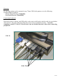
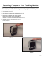
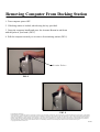
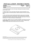
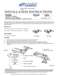
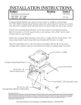
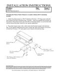
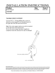
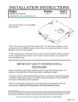
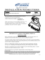
INSTALLATION INSTRUCTIONS
Product
Panasonic CFH2 Vehicle Docking Station
7160-0348
Revision
Form
INST-548
Rev. D
Printing Spec: PS-001
This instruction sheet is for the Gamber-Johnson Panasonic
Toughbook CFH2 Vehicle Docking Station
Gamber-Johnson Part Numbers: 7160-0348 (-P)
7160-0248-01 (-P)
*These instructions are for the docking station only. For
instructions on features, set-up and operation of the
Toughbook CFH2 computer, please refer to the manuals
provided by Panasonic with the computer.
IMPORTANT SAFETY INFORMATION for
INSTALLERS
Safety is dependent on the proper installation and servicing of this docking station. It is
important to read and follow all instructions before installing this product.
To properly install a Gamber-Johnson docking station you must have a good understanding
of electrical procedures and systems, along with proficiency in the installation and service of
electrical and/or computer equipment.
There are no adjustments required at any time of the electrical components within the
docking station. Opening the docking station housing will void the product warranty.
Panasonic recommends using a Lind Auto Adapter to power the docking station. It can be
ordered from Gamber-Johnson (Item No. 11798)
Keep foreign objects away from the Expansion Bus on the docking station.
Product Mounting Disclaimer
Gamber-Johnson is not liable under any theory of contract or tort law for any loss, damage, personal injury, special, incidental or consequential damages for personal injury or other damage
of any nature arising directly or indirectly as a result of the improper installation or use of its products in vehicle or any other application. In order to safely install and use Gamber-Johnson
products full consideration of vehicle occupants, vehicle systems (i.e., the location of fuel lines, brakes lines, electrical, drive train or other systems), air-bags and other safety equipment is
required. Gamber-Johnson specifically disclaims any responsibility for the improper use or installation of its products not consistent with the original vehicle manufactures specifications
and recommendations, Gamber-Johnson product instruction sheets, or workmanship standards as endorsed through the Gamber-Johnson Certified Installer Program.
© copyright 2011 Gamber-Johnson, LLC
If you need assistance or have questions, call Gamber-Johnson at 1-800-456-6868
1 of 6
Components
Latching
Mechanism
Actuator Button
Front View
Lock (Optional)
Expansion Bus
FIG. A
Bottom View
DC-IN Jack
External Display Port
DC IN 16V
MINI DSUB 15-PIN Female
Serial Port
DSUB 9-PIN Male
Will not support serial mouse.
USB Ports (3 ports)
(4 PIN, USB2.0)
FIG. B
LAN Port
IEEE 802.3 10Base-T / IEEE 802.3u
100Base-TX
2 of 6
Installation Recommendations
Conduct a "Bench Test"
Gamber-Johnson strongly advises a "bench test" be conducted to verify that all electronic
and software issues are resolved prior to installation:
1. Make sure computer is operational by itself.
2. Insert computer into docking station and verify that the display is operating in the
dock.
3. Interconnect entire assembly and verify start-up of all components, including other
equipment (printers, modems, scanners, etc.).
Attaching Strain Relief Bracket
A cable Strain Relief Bracket is provided in the hardware bag. This bracket will
provide a mounting platform to secure all interface cables.
1. Lay docking station on its front face to expose rear mounting
surface
2. Align the Strain Relief Bracket mounting holes with the two
holes in the metal housing on the bottom of the docking
station (FIG C).
3. Using a #2 Phillips Srew Driver secure the Strain Relief
Bracket using the two #8-32 X.25 Screws provided in the
hardware bag.
Metal Housing
FIG. C
Strain Relief
Bracket
#8-32unc x .25 Mounting Screws
3 of 6
Mounting
The docking station can be mounted to any 75mm VESA hole pattern, or to the following
Gamber-Johnson products:
- VESA Adaptor Bracket (7160-0206)
- Wall Mount Bracket (7160-0195)
Connecting Peripherals
Restrain the power, ethernet, and USB cables to the strain releif bracket with the cable ties provided as
shown below. The video and serial cables have jack screws to hold them in place. To assure
compliance with FCC, Part 15, Class B rules, only use shielded interface cables when connecting
peripherals.
FIG. D
Cable Ties
4 of 6
Inserting Computer Into Docking Station
CAUTION:
Turn computer power OFF when inserting and removing computer from docking station
1. Turn computer power OFF.
2. Insert bottom of computer into docking station (FIG G).
3. Push the top of computer back into the docking
station until an audible "click" is heard and the
computer is secured by the Latching Mechanism (FIG H).
4. (Optional) The Key Lock can now be used for
security purposes.
FIG. G
FIG. H
5 of 6
Removing Computer From Docking Station
1. Turn computer power OFF.
2. If docking station is locked, unlock using the key provided.
3. Grasp the computer handle and press the Actuator Button in and down
with the palm of your hand. (FIG I).
4. Pull the computer towards you to remove from docking station (FIG J).
Actuator Button
FIG. I
FIG. J
Product Mounting Disclaimer
Gamber-Johnson is not liable under any theory of contract or tort law for any loss, damage, personal injury, special, incidental or consequential damages for personal injury or other damage
of any nature arising directly or indirectly as a result of the improper installation or use of its products in vehicle or any other application. In order to safely install and use Gamber-Johnson
products full consideration of vehicle occupants, vehicle systems (i.e., the location of fuel lines, brakes lines, electrical, drive train or other systems), air-bags and other safety equipment is
required. Gamber-Johnson specifically disclaims any responsibility for the improper use or installation of its products not consistent with the original vehicle manufactures specifications
and recommendations, Gamber-Johnson product instruction sheets, or workmanship standards as endorsed through the Gamber-Johnson Certified Installer Program.
© copyright 2009 Gamber-Johnson, LLC
6 of 6