1
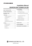
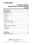
COLOR SECTOR SCANNING SONAR
MODEL
CH-37
The paper used in this manual
is elemental chlorine free.
FURUNO Authorized Distributor/Dealer
9-52 Ashihara-cho,
Nishinomiya 662-8580, JAPAN
Telephone :
0798-65-2111
Fax
0798-65-4200
:
All rights reserved.
Printed in Japan
FIRST EDITION : JUL. 1998
E2
Pub. No. IME-13030-E2
( HIMA ) CH-37
: JUL. 28, 2006
*00080821301*
*00080821301*
*00080821301*
*IME13030E20*
*IME13030E20*
*IME13030E20*
SAFETY INSTRUCTIONS
WARNING
WARNING
Install the specified transducer tank
in accordance with the installation
instructions. If a different tank is to be
installed the shipyard is solely responsible for its installation, and it should
be installed so the hull will not be
damaged if the tank strikes an object.
ELECTRICAL SHOCK HAZARD
Do not open the equipment
unless totally familiar with
electrical circuits and
service manual.
Only qualified personnel
should work inside the
equipment.
The tank or hull may be damaged if the
tank strikes an object.
Turn off the power at the switchboard
before beginning the installation.
Fire or electrical shock can result if the
power is left on.
If a steel tank is installed on a wooden
or FRP vessel, take appropriate
measures to prevent electrolytic
corrosion.
Do not install the equipment where it
may get wet from rain or water splash.
Electrolytic corrosion can damage the
hull.
Water in the equipment can result in fire,
electrical shock or equipment damage.
Be sure that the power supply is
compatible with the voltage rating of
the equipment.
Be sure no water leaks in at the transducer installation site.
Connection of an incorrect power supply
can cause fire or equipment damage. The
voltage rating of the equipment appears
on the label above the power connector.
Water leakage can sink the vessel. Also
confirm that the transducer will not loosen
by ship's vibration. The installer of the
equipment is solely responsible for the
proper installation of the equipment.
FURUNO will assume no responsibility for
any damage associated with improper
installation.
i
CAUTION
Ground the equipment to
prevent electrical shock and
mutual interference.
Observe the following compass safe
distances to prevent deviation of a
magnetic compass:
Display
unit
Standard
compass
Steering
compass
2.2 m
1.6 m
WORKING WITH THE SONAR OIL
Precautions
• Keep oil away from eyes. Wear protective
gloves when working with the oil. The oil
can cause inflammation of the eyes.
• Do not touch the oil. Wear protective
gloves when working with the oil. The oil
can cause inflammation of the skin.
• Do not ingest the oil. Diarrhea or vomiting
can result.
• Keep the oil out of reach of children.
Emergency
• If the oil enters eyes, flush with clean
water about 15 min. Consult a physician.
• If the oil contacts skin, wash with soap
and water.
• If the oil is ingested, see a physician
immediately.
Disposal of oil and its container
Dispose of oil and its container in accordance with local regulations. For further
details, contact place of purchase.
Storage
Seal container to keep out foreign
material. Store in dark place.
ii
TABLE OF CONTENTS
EQUIPMENT LISTS ................................................................................................... iv
SYSTEM CONFIGURATION ................................................................................... v
MOUNTING
1.1
1.2
1.3
1.4
1.5
1.6
1.7
1.8
Hull Unit ..................................................................................................................... 1-1
Transceiver Unit ...................................................................................................... 1-13
Display Unit ............................................................................................................. 1-14
Grounding the Display Unit and Transceiver Unit ................................................... 1-14
Motion Sensor MS-100 (Option) ............................................................................. 1-15
External Interface (Option) ...................................................................................... 1-15
Logarithm Amplifier Video Sounder ........................................................................ 1-17
Clinometer BS-704 (option) ..................................................................................... 1-19
WIRING
2.1
2.2
Wiring Among Units ................................................................................................... 2-1
Synchronizing Transmission with Echo Sounder or Other Sonar ............................. 2-4
ADJUSTMENTS
3.1
3.2
3.3
3.4
3.5
3.6
General Checks ........................................................................................................ 3-1
Adjustment of Transceiver Unit ................................................................................. 3-2
Heading Alignment .................................................................................................... 3-3
Adjustment of Motion Sensor, Clinometer ................................................................. 3-4
Soundome Painting ................................................................................................... 3-5
LED Status ................................................................................................................ 3-6
CHANGING SPECIFICATIONS
4.1
System Menu ............................................................................................................ 4-1
INSTALLATION MATERIALS, SPARE PARTS, ACCESSORIES .... A-1
OUTLINE DRAWINGS ............................................................................................ D-1
INTERCONNECTION DIAGRAM ...................................................................... S-1
iii
EQUIPMENT LISTS
Standard Supply
Name
Type
Code No.
Qty
Remarks
Display Unit
CH-370
–
1
Transceiver Unit
CH-341
–
1
60/81/113/162 kHz, select one
Hull Unit
CH-342
–
1
60/81/113/162 kHz, 24/32 VDC,
Shaft length 1.17/2.2/3.8 m
CP06-01100
000-068-457
CP06-01110
000-068-458
CP06-01120
000-068-459
Spare Parts
SP06-01000
000-068-454
1 set
Accessories
FP06-01600
000-068-460
1 set
Installation Materials
iv
Select
one
Cable length: 15 m (standard supply)
Cable length: 30 m
Cab le length: 50 m
Hood, vinyl cover
Optional Equipment
Name
Type
Code No.
Remarks
Motion Sensor
MS-100
Clinometer
BS-704
Remote Control Box
CH-343
Steel Retraction Tank
06-007-1570
000-065-066
1.0 m
Steel Retraction Tank
SHJ-0001
000-066-643
1.8 m
Steel Retraction Tank
06-007-1571
000-065-070
3.5 m
FRP Retraction Tank
SHJ-0022
000-066-644
1m
FRP Retraction Tank
06-007-1573
000-065-067
1.8 m
Aluminum Retraction Tank
OP10-5
000-069-763
1 m, with inst. materials
Rectifier
RU-1746B-2
000-030-439
110/220 VAC, 2 sets required
E/S Interface
VI-1100A
000-021-805
Handle
OP03-70
008-423-420
Loudspeaker
SC-05WR
000-136-156
4 ohm
Cable Assembly
MJ-A6SPF0012-050
000-134-424
64S4073-1, 5 m, 6 pin - 6 pin
Cable Assembly
MJ-A6SPF0012-100
000-133-817
64S4071-1, 10 m, 6 pin - 6 pin
Cable Assembly
MJ-A6SPF0011-050
000-132-244
03S9202-1, 5 m, 6 pin - 4 pin
Cable Assembly
MJ-A6SPF0011-100
000-132-336
03S9226-1, 10 m, 6 pin - 4 pin
5-pair Twisted Cable
CO-SPEVV-SB-C 0.2 x 5P
000-560-451
5m
5-pair Twisted Cable
CO-SPEVV-SB-C 0.2 x 5P
000-560-452
10 m
5-pair Twisted Cable
CO-SPEVV-SB-C 0.2 x 5P
000-560-417
15 m
5-pair Twisted Cable
CO-SPEVV-SB-C 0.2 x 5P
000-103-868
20 m
48-core Cable
06S4056
000-126-160
For extension of cable between
hull unit and transceiver unit,
specify length
Filter
FP02-02620
002-007-290
External E/S Interface
OP06-13
000-068-455
External Monitor Interface
OP06-14
000-068-456
v
v
SYSTEM CONFIGURATION
OPTIONAL SUPPLY
STANDARD SUPPLY
DISPLAY UNIT
CH-370
LOUDSPEAKER
SC-05WR
EXTERNAL
MONITOR
Clinormeter
MOTION
SENSOR or BS-704
MS-100
External
Interface
OP06-13
(Built-in)
24-32V DC
External
Interface
OP06-14
(Built-in)
06S4067 15/30/50M
02S8040 6M
250VDPYCYS-2
REMOTE CONTROL BOX
CH-343
250V-DPYCYS-2
250V-DPYCYS-2
250V-DPYCYS-2
250V-DPYCYS-2
: Connector to fitted at installation
: Connector fitted at factory
: Crimp-on lug to be fitted at installation
NOTE 1: Two sets of rectifiers are necessary for AC mains.
NOTE 2: DC ship's mains only. For AC ship's mains, the power
is supplied directly from the rectifier unit to the transceiver unit.
vi
Hull unit assembly combination
R
/
L
D
R
I
V
E
Power
Freq.
Type
Code No.
113kHz
U
N
I
T
113kHz
Standard
Option
S
H
A
F
T
Type
Code No.
Type
Code No.
Type
Code No.
3.7 m cable
2.7 m cable
5.3m cable
S
O
U
N
D
O
M
E
Power
Freq.
Type
Code No.
Power
113
Freq.
Type
Code No.
Power
Freq.
Type
Code No.
113
113
T
A
N
K
Mat.
Steel
Type
Code No.
Mat.
Type
Steel
Code No.
Mat.
Type
Code No.
Steel
Alum.
vivivivivivivi
vii
This page is intentionally left blank.
MOUNTING
1.1
Hull Unit
General mounting considerations
• Noise and air bubbles will affect performance.
• Keep the transducer away from oil. Oil can corrode the cable.
• Do not expose the transducer to hot water. Hot water can damage the transducer.
• Do not turn on the equipment with the transducer exposed to air. Exposing the
transducer to air may damage it.
Installation position considerations
Discussion and agreement are required with the dockyard and ship owner in
deciding the location for the hull unit. When deciding the location, take into account the following points:
• Select an area where propeller noise, cruising noise, bubbles and interference
from turbulence are minimal. Generally, the point at 1/3 to 1/2 of the ship’s
length from the bow or near the keel is the best. On-the-keel installation is
advantageous for minimizing oil consumption in comparison with off-the-keel.
If the hull unit cannot be installed on the keel, the center of the retraction tank
should be within 1 meter of the keel to prevent a rolling effect.
1/2
Within 1 m
1/3
Figure 1-1 Installation location for hull unit
• Select a place where interference from the transducers of other sounding equipment is minimal. The hull unit should be at least 2.5 meters away from the
transducers of other sounding equipment.
• An obstacle in the fore direction not only causes a shadow zone but also aerated water, resulting in poor sonar performance. Be sure to locate the transducer well away from any obstacle in the fore direction.
1-1
Mounting method
A typical mounting method is shown in the outline drawing at the back of this
manual. Consult ship’s owner, dockyard and user to determine appropriate mounting method. Pay attention to safety (strength, watertighness) first, followed by
ease of maintenance and inspection.
Tank length
Shorten the transducer tank so the transducer is lowered into water as deep as possible.
Cable gland
Washer
Pay particular attention to the tank length Lt.
Determine the length of the main shaft as
described in the paragraph “Assembling and
mounting of hull unit.”
Note 1: Do not shorten the 1 meter retraction tank. Shortening it may also necessitate
shortening of the top part of the main shaft,
thereby destroying the watertight construction of the 1.17 meter shaft.
Note 2: When the retraction tank is constructed locally, finish it so that welding beads
do not protrude on the inner surface of the
tank. The tank guide will hit the bead, burning out the raise/lower motor. Also, do not
position the welding bead in the ship’s foreaft line.
Note 3: Use of other manufacturer’s tank is
permitted. However, the dimensions should
be the same as those in the transducer tank
outline drawing.
Gasket
Main shaft
(1.17 m)
Welding bead
Welding bead
Figure 1-1 Transducer tank
length and welding bead
Mounting of transducer tank
Install the transducer tank referring to the hull
unit outline drawings at the back of this
manual.
Note: Locate one of the bolt holes 10° to port
to minimize mechanical shock at the raise/
lower block during pitching and rolling.
1-2
10°
Figure 1-2
Transducer tank
Assembling and mounting of hull unit
The hull unit is shipped disassembled as the parts shown in the hull unit kit on
pages 1-10 and 1-11. Assemble the hull unit as shown in the procedure below.
Necessary tools
Name
Specification
Remarks
Wrench
For M10 (Hex. size 17 mm)
Wrench
For M20 (Hex. size 20 mm)
Pipe Wrench
55 mm
Ball Wrench
Hex size 4 mm
Supplied with hull unit kit
1. Unscrew 10 pieces of socket head cap screws with the ball wrench (supplied)
to detach the soundome.
Rotate 3 or 4 turns
by hand to make
sure that turning
mechanisms are
functioning properly.
Socket head cap screw
(10 pcs, M5 x 30)
Spring washer
O-ring
Kinoruster: Anti-crevice
corrosion sealant (supplied)
Apply Kinoruster.
Remove
SOUNDOME
Protective sponge
Figure 1-3 Detaching the soundome
1-3
2. Fill the soundome with sonar oil 6 cm below the top of the dome. (Use only
the specified sonar oil. Use of other sonar oils may affect performance.) Reattach the soundome.
Frequency (kHz)
60
81
113
CAUTION
162
Sonar oil 4L
(000-824-033)
No
Yes
Yes
Yes
Super sonar oil 4L
(000-804-568)
Yes
No
No
No
Ball
wrench
WORKING WITH THE SONAR OIL
Precautions
• Keep oil away from eyes. Wear protective
gloves when working with the oil. The oil
can cause inflammation of the eyes.
• Do not touch the oil. Wear protective
gloves when working with the oil. The oil
can cause inflammation of the skin.
• Do not ingest the oil. Diarrhea or vomiting
can result.
• Keep the oil out of reach of children.
Emergency
• If the oil enters eyes, flush with clean water
Sonar oil
about 15 minutes. Consult a physician.
• If the oil contacts skin, wash with soap and
water.
• If the oil is ingested, see a physician
5 cm
immediately.
Use packing material
to support soundome.
Disposal of oil and its container
Dispose of oil and its container in accordance with local regulations. For further
details, contact place of purchase.
Storage
Seal container to keep out foreign
material. Store in dark place.
Figure 1-4 Filling the soundome with sonar oil
3. Shorten the main shaft by the length of Lt + 110 mm, where Lt is the length of
the retraction tank. When the retraction tank length is 1 meter do not shorten
the 1.17 meter main shaft.
Supplied Length: 1.17 m (2.2 m, 3.8 m)
Lt + 110 mm
Take care not to
scratch.
Chamfer edge to
protect O-ring from
damage.
Figure 1-5 How to shorten the main shaft
1-4
4. Fasten the main shaft to the soundome assembly as follows:
a) Attach screw lock nut to main shaft.
b) Fully screw main shaft into the soundome neck, and then unscrew by four
turns. Coat threads with adhesive (HIGH SUPER).
c) Screw in main shaft completely and tighten the lock nut with spanner.
d) Tighten socket-set screw on lock nut.
e) Fasten two reinforce metal fittings to connect the main shaft and the
soundome assembly securely (Not using the stopper washer).
While holding soundome neck with pipe
wrench, tighten lock nut with wrench.
Lock nut
Reinforcement
metal fittings
Apply adhesive
(HIGH SUPER).
Set screw
Reinforcement
metal fittings
M10 × 100
SW, PW, Nut
Figure 1-6 How to fasten main shaft to soundome assembly
1-5
5. Clean the main shaft and pass it through the main body flange.
Check that O-ring
is in position.
Main body flange
Figure 1-7 Passing main shaft through the main body flange
6. Set the grease cotton to the main body flange and tighten the grease cotton
retainer temporarily.
Space joints of grease
cotton 120° apart and push
them into body flange.
Wind grease cotton
onto main shaft and
cut it as shown below.
Flat washer
Figure 1-8 Installing grease cotton on the main shaft
7. Temporarily fasten the fastening band onto the main shaft at the location shown
below.
Lt: Tank Length
Lt - 430 mm
Fastening band
Figure 1-9 Fastening the fastening band on the main shaft
8. Inscribe bow mark at the top of the main shaft. Pass pipe clamp through the
main shaft and install washer, gasket, and cable gland.
1-6
Pipe clamp
Inscribe bow mark,
referring to the bow mark
on the soundome.
Gasket
Cable gland
Hold here with
pipe wrench.
70
Flat washer
Pipe cap
3
Tighten cable gland for
gap of approx. 3 mm.
For 2.2 m, 3.8 m shaft
Figure 1-10 Passing pipe clamp, gasket, flat washer and cable gland on main shaft
9. Fasten the hull unit to the transducer tank, orienting it so the ship’s fore-aft
line crosses the front panel of the raise/lower drive block at an angle of approximately 45 degrees.
M20 x 90 (8 pcs)
M20 Flat washer
45°
BOW
Outer edges of main body
flange and tank should be
in line with one another.
Wipe off foreign material.
M20 F.W.
M20 S.W.
M20 Nut
Orient the hull unit as above
to minimize shock and vibration
on the raise/lower drive block
when ship is pitching and
rolling.
Apply Kinoruster.
CAUTION:
1. Do not drag hull unit on floor.
2. Do not rest hull unit against wall.
Figure 1-11 Fastening the hull unit to the transducer tank
1-7
10.Install the raise/lower drive block as follows:
a) Rotate the main shaft so the bow mark faces ship’s bow.
b) Install the raise/lower drive block onto the main body flange.
c) Fix the main shaft with the shaft retainer.
d) Loosen the fastening band, slide it up to the shaft retainer and fasten it.
e) Check that the distance from the top of the main shaft to the top of the
shaft retainer is as follows:
1.17 m main shaft: 75 mm
Main shaft cut at Lt + 110 mm: 15 mm
If not as shown above, loosen shaft retainer and fastening band to adjust the
distance. This will place the bottom of the soundome 10 mm above the bottom of the retraction tank when the soundome is retracted.
Raise/lower
drive block
Shaft retainer
1.17 m shaft: 75 mm
Shortened shaft: 15 mm
Fastening band
Bow
mark
Fasten for a gap of
approximately 1 mm.
Fastening band
10 mm
Figure 1-12 Installing the raise/lower drive block
11.Tighten the grease cotton retainer for a gap of 7 to 9 mm.
1-8
Grease cotton retainer
7 to 9 mm
Grease cotton
Figure 1-13 Tightening the grease cotton retainer
Checking manual raise/lower of transducer with hand
crank
Perform this check after all wiring has been completed. Ship’s mains power must
applied to the hull unit, otherwise the magnetic brake of the raise/lower motor
activates, disabling the manual raise/lower gears.
1. Turn off the breaker on the hull unit.
2. Detach the brake-off switch cover.
3. Set hand crank to the screw shaft gear and turn it while pressing the brake-off
switch.
4. The transducer should rise/lower smoothly with even force in upper to lower
limits. If not, the centers of the main body flange and the retraction tank are
not aligned. Adjust the hull mounting position if necessary.
Raise
Brake Off
switch
Lower
Breaker
Raising/lower manually without
connecting ship's mains may
damage motor.
Figure 1-14 How to use the hand crank
1-9
Hull unit installation materials
1-10
000-824-033
1-11
60 kHz
SUPER SONAR
OIL 4L
(000-804-568)
No.
32
33
34
35
36
NAME
REINFORCEMENT
METAL FITTING
OUTLINE
DESCRIPTIONS
06-018-3305-0
CODE NO.
CODE NO.
8
000-864-131
M10 SUS304
SPRING WASHER
CODE NO.
4
000-864-261
M10 SUS304
HEX. NUT
CODE NO.
1-12
4
000-141-563
M10 SUS304
FLAT WASHER
2
CODE NO. 100-270-580
M10X100 SUS
HEX. BOLT
Q’TY
4
000-863-111
REMARKS
Transceiver Unit
Mounting considerations
• The mounting location should be well ventilated and dry.
• The unit can be mounted on a bulkhead or the deck. The unit weighs 8.5 kg so
reinforce the mounting location if necessary.
• Secure the maintenance space shown in drawing below for ease of maintenance and service.
350
282
75
32
505
475
342
32
100
75
(30)
66
20
310
120
1.2
4 - ∅12 Fixing hole
Cable entry
Figure 1-15 Mounting dimensions for the transceiver unit
1-13
1.3
Display Unit
Mounting considerations
Select the mounting location considering the following conditions:
• Select a location where the display unit can easily be operated while observing
the fishing ground or area surrounding the vessel.
• Locate the unit at least 1 meter away from equipment which contains magnets (radar magnetron, loudspeaker).
• A magnetic compass will be affected if placed
too close to the display unit. Observe the following compass safe distances to prevent deviation to a magnetic compass: Standard
compass, 2.2 m, Steering compass, 1.6 m.
Within 45°
• Select a location not exposed to direct sunlight, water splash or hot air.
• Select a location which accommodates the
viewing angle shown at right.
Figure 1-16 Display unit
1.4
Grounding the Display Unit and Transceiver Unit
Ground the equipment with a copper strap or ground wire to prevent interference.
DISPLAY UNIT
TRANSCEIVER UNIT
Cable clamp
Signal cable
06S4061
Earth terminal
Remove vinyl sheath; ground
cable by cable clamp.
Earth terminal
CAUTION
Ground the equipment to
prevent electrical shock
and mutual interference.
Figure 1-17 Location of earth terminals on display unit and transceiver unit
1-14
1.5
Motion Sensor MS-100 (Option)
The MS-100 measures ship’s pitching and rolling angles with sensors using the
principles of the gyroscope. The MS-100 is free from error caused by ship’s vertical and horizontal motion. Therefore, it can be installed at any convenient location. However, ship’s semi-permanent inclination due to loading imbalance cannot
be detected. Compensate for this as described in Chapter 3.
Mounting considerations
FORE
• Vibration in the mounting area should be
minimal.
θ ≤ 5°
• Locate the unit away from areas subject
to water splash.
AFT
• The ambient temperature should not exceed 50°C.
Figure 1-18 Motion sensor MS-100
Mounting procedure
Orient the FORE mark on the unit toward the ship’s bow and mount the unit level
to within 5° in all directions.
1.6
External Interface (Option)
This section shows how to install External E/S Interface (type OP06-13) and/or
the External Monitor Interface (type OP06-14).
For connecting external monitor, prepare mini D-SUB 15 pin cable (male-male).
Recommended cable : EVNPSO5-50ft, manufactured by Black Box Japan Co.,Ltd.
External monitor interface installation kit
Part
Type, Q'ty
Code No.
Q'ty
External Monitor Interface Assy.
-
-
1
XH Connector Assy.
06-313 (13-13P)
006-550-840
1
Screw
M3x6
000-881-103
4
Screw
M3x8
000-881-404
1
Cable Ties
No.249
000-515-871
1
1-15
External E/S interface installation kit
Part
Type, Q'ty
Code No.
Q'ty
-
-
1
External E/S Interface Assy.
XH Connector Assy.
06-312 (6-6P)
006-550-830
1
Screw
M3x6
000-881-103
4
Screw
M3x8
000-881-404
1
Cable Ties
No.249
000-515-871
1
1. Remove the display unit cover.
2. Remove the dummy plate at the rear of the display unit.
Remove this dummy plate
and fasten External Interface module here.
Figure 1-19 Display unit, rear view
3. Connect XH connector assy. to the Interface Module.
4. Fasten the Interface Module to the display unit with M3 x 6 screws and one
M3 x 8 screw.
For connecting External Monitor Interface (OP06-14) and External E/S interface (OP06-13), remove ESIF Board from OP06-13, and fix ESIF Board on
OP06-14.
For connecting logarithm amplifier video sounder, refer to next page.
5. Connect between J2 on the ESIF Board (06P0237) and J3 on the MAIN Board;
connect between J1 on the RGB-BUFF Board (03P9229) and J4 on the MAIN
Board.
1-16
6. Bind cables with the cable tie (supplied).
Pass cables from RBG-BUFF
Board (03P9229) through clamp.
Bind cables
with cable tie.
J4
Fix External Interface module
with M4 x 8 screws.
External
Interface module
FRONT
REAR
J3
MAIN Board
06P0227
Figure 1-20 Display unit, cover removed, right side view
7. Close the cover.
1.7
Logarithm Amplifier Video Sounder
For connecting external video souder (logarithm amplifier:FCV-291,292,1000),
modify ESIF board of OP06-13 (as below) and the INTERFACE UNIT VI-1100A.
For INTERFACE UNIT VI-1100A modification, refer to installation manual of
INTERFACE UNIT VI-1100A.
Modification of E/S interface
1. Remove chip resistor R14 from ESIF board (06P0237).
2. Solder vinyl wire between TP2 and TP4.
TP4
R14 TP2
06P0237
Remove R14
J1
TP0
TP4
TP3
TP1
R14 TP2
Vinyl wire
06P0237
1-17
Note 1: Set “RES.COLOR” field in the E/S menu to “LOG”.
Note 2: Adjust “GAIN ” and “N.L.” of E/S memu.
1-18
1.8 Clinometer BS-704 (Option)
The clinometer detects ship’s inclination caused by ship’s rolling and pitching
and its output is used to stabilize the sonar beam against rolling and pitching.
The clinometer is, in principle, a pendulum. It measures the inclination of the ship
by sensing the direction of gravity acted on it and therefore when installed on a
ship, it should be placed on or near the rotation axes of the ship’s rolling and
pitching. If it is placed away, upward from the axes, the measured value becomes larger than the correct value. On the contrary, if it is placed below the
axes, the measured value becomes smaller. The same can be said when it is
placed far to the left or right from the axes.
The rotation axes of pitching and rolling are theoretically considered to be located on the level of the ship’s draft and in the center of ship. In other words, it
can be said as follows.
1)
Vertical position of the pitching and rolling axes is on the draft level of the
ship.
2)
Horizontal position of the rolling axis is in the center of ship’s port-starboard
line.
3)
Horizontal position of the pitching axis is in the center of ship’s fore-aft line.
From 1), 2) and 3) above, the crossing point of the two axes is indicated by the
black dots in Figure 1-21. The clinometer should be mounted as close as possible to this point.
Pitching Axis
Rolling Axis
Figure 1-21 Installation Position of Clinometer
1-19
Cautions:
(1) The vicinity of the hull unit (on the ship’s bottom) is too low and should be
avoided, since the polarity of the measured value is reversed.
(2) When it is impossible to install the clinometer on the intersecting point of
both rolling and pitching rotational axes, a special effort should be made to
install it at place where the vertical distance to the intersecting point is
minimum.
(3) The clinometer should be installed on the horizontal plane.
(4) Install the clinometer with the bow mark pointing in toward the
ship’s bow.
1-20
WIRING
2.1
Wiring Among Units
• The figure on the next page shows wiring among units.
• The signal cables are fitted with connectors. Connect the cables to the display,
transceiver and hull units referring to the interconnection diagram and the drawing on page S-1.
• The power cable should be arranged locally. Use power cable type DPYCYS-2
and DPYCYS-1.25 (both Japan Industrial Standard cables) or equivalent cables.
Attach supplied power connector as shown below.
Ground armor through connector clamp.
#1 pin (+)
#2 pin (-)
#3 pin
Conductor*
DPYCYS-1.25
S = 1.25 mm2
φ = 14.1 mm
Insulator
Inclusion
Tape
Braid
Sheath
Armor
Vinyl sheath
DPYCYS-2.0
S = 2.0 mm2
φ = 15.2 mm
DPYCYS-1.25, DPYCYS-2
Figure 2-1 Power cable DPYCYS-1.25, DPYCYS-2
• Install the main switch for the sonar where it can be easily accessed. Turn off
this switch when the sonar is not being used, to reduce power consumption
and to prevent the transducer from slipping by vibration.
• For AC mains, use two rectifiers RU-1746B, one for the display and transceiver
units and the other for the hull unit.
2-1
2-2
DC 24-32V
BS-704
or MS-100
ClLINOMETER MOTION SENSOR
LOUDSPEAKER
SC-05WR
EXTERNAL DISPLAY
E/S
DPYCYS-2
COPPER STRAP
1+
23 SHIELD
NAV1 NMEA
NAV2 NMEA
DPYCYS-2
Ground armor
at terminal
CH-370
DISPLAY UNIT
DPYCYS-2
DPYCYS-1.25
Figure 2-2 Cabling diagram
Ground
armor at
terminal
Front side
Pass three cables
thru proper cable
entry holes.
Rear side
Note)
Ground
Terminal
Note)
Ground armor by
metal clamp.
2-3
2.2
Synchronizing Transmission with Echo Sounder
or Other Sonar
To synchronize transmission of the CH-37 with an echo sounder or other type of
sonar, connect it as shown below.
Connections for synchronizing Tx with other E/S, sonar
DISPLAY UNIT
06P0228
E/S, SONAR
J3
KP1 > 3 >
EXT SW > 5 >
GND > 8 >
KP OUT
+5 V to 15 V
CH-37 accepts a positive
KP with amplitude of 5 V
to 15 V.
GND
Make a hole for cable entry at the left side of the rear panel.
Figure 2-3 Connection of display unit to other sonar
FRONT
REAR
J3
MAIN Board
06P0227
SNR Board
06P0228
Figure 2-4 Display unit, cover removed, right side view
2-4
Menu setting
1. Press the MENU key.
2. Select SONAR at the top of the menu.
MENU :
SONAR
BOTTOM/3D
DUAL
TX RATE (MAX 10)
:
10
TX PULSE LENGTH
:
LONG
SHORT
TX OUTPUT POWER
:
A
B
TX EXT SYNC
:
OFF
ON
IR
:
OFF
ON
STABILIZER
:
OFF
ON
COLOR
:
16
8
RES. COLOR
:
LOG
LINEAR
EXIT
:
E/S
C (MAX)
SQUARE
PRESS MENU KEY
Figure 2-5 SONAR menu
3. Set TX EXT SYNC to ON.
4. Press the MENU key.
Note: Outputting KP of CH-37 to other sonar, echo sounder
DISPLAY UNIT
06P0228
J3
KPO > 2 >
GND > 8 >
(E/S, SONAR)
CH-37 accepts positive
KP with amplitude of
0V to 5V.
Outputting KP of CH-37 to other sonar, echo sounder
2-5
This page is intentionally left blank.
ADJUSTMENTS
3.1
General Checks
Table 3-1 General checks
Check Item
Check point, Rating
On-keel Installation
Flush with keel
Retraction tank level
Off-keel Installation
Within 1 m
Above keel
Clearance between transducer and bottom of
retraction tank when transducer is
completely retracted by hand crank.
1 cm
Transducer travel (lowered by hand crank)
Note: When checking, a clearance of
approximately 1 meter is required under the
bottom of the transducer.
Manual raise/lower of transducer
Minimum 30 cm
Transducer can be raised/lowered smoothly
with hand crank.
Transducer heading
Bow mark inscribed on main shaft
should face ship's bow.
(Continued on next page)
3-1
Table 3-1 General checks (con’t)
Check Item
3.2
Check point, Rating
Wiring check
• All cables are correctly connected.
• All lead wires are tightly fixed with contact
pins or crimp-on lugs.
• All screws are firmly fastened.
• Cables are firmly secured.
• Cable shields are properly grounded.
Rejecting source of noise and interference
• Noise generating machinery (motor, radiotelephone, TV set, etc.) are not placed
nearby.
• Magnetic devices are not placed in the
vicinity of display unit.
Ground
Each unit is grounded with a copper strap.
Ship's mains voltage
Ship's mains voltage is stable 24 or 32 VDC.
Watertightness
Water should not leak from the main body
flange or along the main shaft.
Heading alignment
A target is displayed on the correct bearing.
Adjustment of Transceiver Unit
Selecting audio frequency
Select audio frequency of 1000 Hz or 900 Hz by jumper connector JP2 on pcb
06P0192 in the transceiver unit. The default setting is 1000 Hz. Refer to Figure
3-1 for the location of JP2.
Signal offset adjustment
When noise appears on the screen, adjust R61 (offset) on pcb 06P0192. Turning
R61 clockwise slices off low level signals in a similar way to the CLUTTER control on the display unit. (While the CLUTTER control on the display unit eliminates low level signals without changing signal level of strong signals, R61 shifts
signal level of all signals.) When the offset adjustment is necessary, set R61 fully
counterclockwise. Refer to Figure 3-1 for the location of R61.
3-2
Horizontal beamwidth
06P0192
When the user wishes echoes to be displayed in high resolution, turn R40 on pcb
06P0192 clockwise to sharpen horizontal beamwidth. Do not turn it excessively
clockwise, or an echo which should be displayed as a single solid mass may
become hollow or split into smaller, fewer masses. Normally, set R40 at the midpoint of its travel.
HI LO
JP2
R61
R40
Photo No. 2058
Figure 3-1 Transceiver unit, cover opened
3.3
Heading Alignment
1. Locate a target (buoy, etc.) in the bow direction and display it on the screen at
close range. The heading alignment is correct when the target is displayed at
12 o’clock on the screen.
Heading
Buoy
12 o'clock position
When on-screen target is
skewed right, transducer
heading is skewed left.
Figure 3-2 Checking heading alignment
3-3
2. When the heading alignment is incorrect,
loosen four bolts on the shaft retainer and
then rotate the main shaft to align heading.
Shaft retainer
Loosen two bolts
3. Tighten bolts.
Figure 3-3 Main shaft
3.4
Adjustment of Motion Sensor, Clinometer
When the ship has a semi-permanent inclination, offset it as follows. Inclination
of up to 10° can be corrected.
1. Turn on the power while pressing the MENU key. Release the MENU key
when you hear a beep.
2. Select DISPLAY TEST.
** DISPLAY TEST **
Roll, pitch
angles
PROGRAM NO. 0650101-xxx
ROM
OK
SRAM
OK
VRAM
OK
SIO1
OK
SIO2
OK
TX FREQUENCY 60KHZ
ROLL
0
PITCH
0
REMOTE CONTROL
0
0
0
0
0
0
0
0
0
0
0
0
0
0
EXIT : PRESS MENU KEY
Figure 3-4 Display test results
3. Read ROLL/PITCH angles from the display.
3-4
MAIN PANEL
*
*
*
12
12
0
255
12
0
0
0
0
X: 0
Y: 0
0
0
0
0
SUB PANEL
255 255 255 *
*
*
0
0
0
0
0
0 0
0
EXIT
0
0 0
4. By using a clinometer or other means, measure ship’s semi-permanent inclination angle. Take the polarity of the angle as follows:
+
0
–
+
0
–
ROLL: Starboard up: +, Starboard down: PITCH: Stern up: +, Stern down: -
Figure 3-5 Measuring ship’s semi-permanent inclination angle
5. Adjust the potentiometers R35 (ROLL) and R36 (PITCH) on the SNR Board
(06P0228) in the display unit so angle readouts on the screen agree with the
angles measured at step 4.
3.5
Soundome Painting
When the soundome is painted to keep marine life off the transducer, observe
the following precautions:
• Use only anti-fouling paint type MARINE STAR 20 (Manufacturer: Chugoku
Marine Paint Co., Ltd., Japan).
• Paint only the plastic portion of the dome. Painting the metal parts causes corrosion.
Paint area
Figure 3-6 Where to paint the soundome
3-5
3.6
LED Status
Display unit
Settings
Range: 400 m
Tx output power: C (max)
Tilt: 0°
Tx Rate: 10
PWR Board
06P0229
Display unit, top view, cover removed
MAIN Board
06P0227
SNR Board
06P0228
Display unit, side view, cover removed
Figure 3-6 Location of printed circuit boards in the display unit
Table 3-2 LEDs in the display unit
Off:
¡
Flickering: '
LED
PCB
Remarks
No.
MAIN
06P0227
Signal
Status
CR2
+5V
o
CR4
+12V
o
CR5
-12V
o
3-6
Lighting:
o
Table 3-2 LEDs in the display unit (con’t)
Off:
¡
Flickering: '
Lighting:
o
LED
PCB
Remarks
No.
SNR Board
06P0228
PWR Board
06P0229
Signal
Status
CR4
L CONT
¡
Off except when transducer is being lowered.
CR7
TR CLK
'
Flickers while transducer is being trained; off while
transducer is stopped.
CR9
TI CLK
'
Flickers while TILT lever is pressed; off while TILT
lever is released.
CR12
TR 0°
'
Lights momentarily when is trained to 0° direction.
CR14
TR 180°
'
Lights momentarily when is trained to 180° direction.
CR16
TI +10°
¡
Lights momentarily when transducer tilt angle is +10°
or 90°. See * below.
CR17
TI 190°
¡
Lights momentarily when transducer tilt angle is +90°
or 190°. See * below.
CR20
HULL
o
Lights while ship's mains is supplied to hull unit.
CR21
KP
'
Flickers during transmission.
CR21
+5V
o
CR22
+12V
o
CR25
IN HL
¡
Lights when overvoltage protector operates.
CR26
+115V
o
Power supply for color monitor
CR27
-12V
¡
Lights momentarily when overvoltage protector for
-12V line operates.
CR30
5V
¡
Lights momentarily when overvoltage protector for 5V
line operates.
* In normal operation there is no tilt angle of 190° or +10°.
3-7
Transceiver unit
PRE Board
(06P0191)
MAIN Board
(06P0192)
Photo No. 2058
TX Board
(06P0190)
Photo No. 2057
Figure 3-7 Transceiver unit
Table 3-3 LEDs in the transceiver unit
Off:
¡
Flickering: '
LED
PCB
Remarks
No.
TX Board
06P0190
Signal
Status
CR11
+5V
o
CR12
+12V
o
CR13
+130V
o
CR39
TX1
'
CR40
TX2
'
"
"
"
CR41
TX11
'
"
"
"
CR42
TX2
'
"
"
"
CR43
TX3
'
"
"
"
CR44
TX10
'
"
"
"
CR45
TX9
'
"
"
"
CR46
TX4
'
"
"
"
CR47
TX5
'
"
"
"
CR48
TX8
'
"
"
"
CR49
TX7
'
"
"
"
CR50
TX6
'
"
"
"
Flickers during transmission.
3-8
Lighting:
o
Table 3-3 LEDs in the transceiver unit (con’t)
Off:
¡
Flickering: '
LED
PCB
Remarks
No.
PRE Board
06P0191
MAIN Board
06P0192
PWR Board
06P0172
Signal
Status
CR1
+5V
o
CR2
+12V
o
CR3
-12V
o
CR1
+5V
o
CR2
+12V
o
CR3
-12V
o
CR4
AUD
'
Flickers by audio slgnal.
CR16
FS
o
FS signal
CR17
TVG
'
Digital TVG signal
CR18
LCLK
o
TVG signal latch clock
CR9
-12V
o
CR10
+12V
o
CR11
+5V
o
CR12
+130V
o
3-9
Lighting:
o
Hull unit
Photo No. 2056
DRIVE Board
(06P0193)
Figure 3-8 Hull unit
Table 3-4 LEDs in the hull unit
Off:
¡
Flickering: '
Lighting:
LED
PCB
Remarks
No.
DRIVE Board
06P0193
Signal
Status
CR12
TR0°
'
Lights momentarily when transducer is trained in 0°
direction.
CR13
TR180°
'
Lights momentarily when transducer is trained in
180° direction.
CR14
TI +10°
¡
Lights momentarily when transducer is tilted to +10°
or 90°.
CR15
TI 90°
¡
Lights momentarily when transducer is tilted to 90°.
CR16
+13V
o
CR18
TR CLK
o
Lights when transducer is being trained.
CR19
TI CLK
¡
Lights while TILT level is pressed; goes off when
TILT lever is released.
CR20
+13V
o
3-10
o
CHANGING SPECIFICATIONS
4.1
System Menu
1. Turn on the power while pressing the MENU key. Release the key when you
hear a beep.
2. Select SYSTEM SETTING.
** SYSTEM SETTING **
3D DISPLAY
SHIP’S POSITION
CURRENT DATA
DEPTH DATA
HEADING INDICATION
NORTH MARK
TRACK
HDG/SPD DATA
NAV DATA
:
:
:
:
:
:
:
:
:
DATA FORMAT FOR NAV2
CIF BAUD RATE
TVG CORRECTION
UNIT
V-MODE MANUAL TRAIN
DEGAUSSING INTERVAL
FACTORY SETTING
:
:
:
:
:
:
:
OFF
OFF
OFF
OFF
OFF
OFF
10R
NAV
GPS
DR
NMEA
1200
OFF
m
HALF
30 SEC
NO
ON
L/L
ON
ON
TRUE
ON
20R
CI
LORAN C
DECCA
CIF
2400
1/2
ft
fa
FULL
YES
EXIT : PRESS MENU KEY
Figure 4-1 SYSTEM SETTING menu
3. Select items and options with the arrow keys.
4. To return to normal operation, reset the power.
See the next page for system setting menu description.
4-1
LOP
AZ
LORAN A
OTHERS
4800
1
HIRO
Table 4-1 System setting menu description
Item
Description
3D DISPLAY
Turns 3D mode on/off.
SHIP'S POSITION
Turns position indication on/off and selects position format; latitude
and longitude or Loran LOP.
CURRENT DATA
Turns current (tide) data on/off.
DEPTH DATA
Turns depth indication on/off.
HEADING DISPLAY
Turns heading indication on/off and selects its format; true bearing or
azimuth (16 azimuth bearing).
NORTH MARK
Turns north marker on/off.
TRACK
Selects length of courseline plotting; 10R (ten times the range in use)
or 20R (twenty times the range in use).
HDG/SPD DATA
Selects source of data to be used to plot courseline; NAV (Navigator),
CI (Current Indicator).
NAV DATA
Selects source of position data; GPS, LORAN C LORAN A, DR,
DECCA, OTHERS.
DATA FORMAT FOR NAV2
Selects data format for nav data; CIF (FURUNO) or NMEA.
CIF BAUD RATE
Selects baud rate of CIF data; 1200, 2400, 4800 bps.
TVG CORRECTION
Changes TVG curve to compensate for absorption attenuation of
ultrasonic wave in water. OFF, Standard TVG curve, 1/2, 1/2 of
theoretical absorption value added to TVG curve, 1, Full theoretical
absorption value added to TVG curve.
UNIT
Selects unit of depth measurement. m, meters; ft, feet; fa, fathoms,
HIRO.
V-MODE MANUAL TRAIN
Selects manual training sector width for the vertical fan mode. Half,
half circle, Full, full circle.
DEGAUSSING INTERVAL
Enter interval at which to have the screen degaussed. OFF
degausses the screen at the maximum interval.
FACTORY SETTING
Yes restores default system menu settings.
4-2
A-5
000-068-454
TYPE
SP06-01000
SPARE PARTS LIST FOR
SHIP NO.
ITEM
NO.
CODE NO.
NAME OF
PART
OUTLINE
U
DWG. NO.
OR
TYPE NO.
S
06AR-X-9301 -1 1/1
BOX NO.
P
SETS PER
VESSEL
E
QUANTITY
REMARKS/CODE NO.
WORKING
PER
SET
PER
VES
SPARE
ボールレンチ
1
1
BALL WRENCH
TWB-30
000-803-168-00
FGB0-A
AC125V 10A
ヒューズ
2
FUSE
FGB0 125V 7A
PBF
ヒューズ
3
FUSE
000-155-826-10
000-549-065-00
1
5
000-155-831-10
000-549-013-00
57-30500
1
CONNECTOR
1
000-156-362-10
000-504-000-00
57-30500
FGB0-A 125V
4A PBF
ヒューズ
5
5
FGBO 7A AC125V
コネクタ
4
1
FGBO 10A
AC125V
FUSE
1
5
000-155-851-10
000-127-233-00
FGBO-A 4A
AC125V
MFR'S NAME
FURUNO
ELECTRIC
CO.,LTD.
DWG NO.
C1303-P01-B
1/1
(略図の寸法は、参考値です。 DIMENSIONS IN DRAWING FOR REFERENCE ONLY.)
型式/コード番号が2段の場合、下段より上段に代わる過渡期品であり、どちらかが入っています。 なお、品質は
変わりません。
TWO TYPES AND CODES MAY BE LISTED FOR AN ITEM. THE LOWER PRODUCT MAY BE SHIPPED IN PLACE OF THE
UPPER PRODUCT. QUALITY IS THE SAME.
Jan. 15, '03
D-1
S-1
2
3
4
5
CH-3421 上下装置 HULL UNIT
CH-370 指示器 DIPLAY UNIT
06P0228
A
スピーカー
SPEAKER
SC-05WR
*1
5m
AUD OUT
GND
06P0236
PRC05-P8M
CN3 REMOTE CONTROL
a
S0
b
*1
06S4065
7m
CH-343
リモートコントロール
REMOTE CONTROL
S1
S2
S3
R4
R5
R6
R7
c
d
*3
e
f
g
a
MS-100
動揺検出器
MOTION SENSOR
または OR
BS-704
DATAOUT
B
TXD-H
TXD-C
1
チャ
2
アカ
3
ダイ ORG
4
キ
5
ミドリGRN
SRCN6A13-5S
BRN
RED
*3
YEL
*3
5
5
6
6
SRCN6A16-10P
ミドリGRN
キ
YEL
P
*1
CO-0.2x5P
5/10/15/20m
3
4
1
キ
YEL
P
R/L CONT
TR CW/CCW
TR CLK
TI U/D
TI CLK
RAISE LED
CN7 NAV2 NMEA/CIF
TD2-H
TD2-C
RD2-H
RD2-C
3
4
5
6
7
8
7
9
9
クロ
BLK
10
キ
YEL
クロ
キ
*1
02S8040,6m
VI-1100A
インターフェイス
INTERFACE
BLK
YEL
*4
SRCN6A16-7P
シロ WHT
キ
YEL
10
CN8
1
2
3
GND
AC・SIG
DC・SIG
KP
4
アオ
外部ディスプレイ
EXTERNAL DISPLAY
BLU
*4
D-SUB 15P
5
魚探インターフェイス
6
E/S I/F
7
カラーモニターインターフェイス
CN9 COLOR MONITOR
C
C
C
C
C
C
LOWER LED C
TR 0°C
TR180°C
TI+10°C
TI190°C
HULL PWST C
PSW C
KP C
FS C
TVG C
LCLK C
BEAM
PWR 2
FQ 2
OV
SIG C
AUD C
2
3
5
6
2
7
3
8
4
9
10
5
6
11
7
12
8
13
14
9
10
15
16
11
17
18
13
19
15
16
12
14
20
17
21
22
23
24
25
27
*3
06S4076
*3
LOWER LED
LOWER LED
TR 0°H
TR 0°C
TR180°H
TR180°C
TI+10°H
TI+10°C
TI190°H
TI190°C
HULL PWST
HULL PWST
PSW H
PSW C
KP H
KP C
FS H
FS C
TVG H
TVG C
LCLK H
LCLK C
SCAN
BEAM
PWR 1
PWR 2
FQ 1
FQ 2
TRX PWST
18
19
15/30/50
φ12.5
切断不可
DO NOT CUT
20
21
22
23
28
29
24
25
30
26
31
27
32
28
33
29
34
30
35
31
36
32
37
33
38
34
39
35
40
36
41
37
42
38
43
44
39
40
45
41
46
42
47
48
43
44
49
45
50
46
47
CN5
1
+V(24-32VDC)
2
-V(OV)
50
CH-341 送受信装置
TRANSCEIVER UNIT
7
8
VDA
VDB
φ1
φ2
φ3
φ4
9
VH-10R
1
P
2
3
P
H
C
J1
4
5
P
6
7
P
8
9
10
P
VH-8R
VH-10R
11
12
P
2
3
P
4
5
P
6
7
8
P
VH-6R
13
P
P
2
3
4
5
6
19
20
21
22
23
24
06P0142
TRP1+
TRP1TRP2+
TRP2TRP3+
TRP3TRP4+
TRP4TRP5+
TRP5-
TD1+
TD1TD2+
TD2TD3+
TD3TD4+
TD4TD5+
TD5-
TRP6+
TRP6TRP7+
TRP7TRP8+
TRP8TRP9+
TRP9-
TD6+
TD6TD7+
TD7TD8+
TD8TD9+
TD9-
TRP10+
TRP10TRP11+
TRP11TRP12+
TRP12-
TD10+
TD10TD11+
TD11TD12+
TD12-
VH-10R
J4
1
2
3
4
5
6
7
8
9
10
1
2
3
4
5
6
7
8
1
2
3
4
5
6
WHT
BLK
TB1
5
6
3
4
5
6
7
8
P
P
P
P
P
P
TRP10+
TRP10TRP11+
TRP11TRP12+
TRP12-
1
2
3
4
5
6
8
9
10
11
12
13
14
17
18
19
P
21
22
23
24
25
27
28
29
43
31
P
P
47
3
FQ 1
FQ 2
TRX PWST
4
OV
34
5
SIG
SIG
AUD
AUD
1
2
6
P
7
8
XH-14R
J9
1
P
2
3
P
4
5
P
6
7
*3
H
C
H
C
8
9
12
13
14
PSW H
PSW C
KP H
KP C
FS H
FS C
TVG H
TVG C
LCLK H
LCLK C
SCAN
BEAM
PWR 1
PWR 2
MOTOR
MOTOR
MOTOR
MOTOR
MOTOR
MOTOR
φ4
φ3
φ2
φ1
VDA
VDB
MOTOR
MOTOR
MOTOR
MOTOR
MOTOR
MOTOR
φ4
φ3
φ2
φ1
VDA
VDB
+13V
+13V
+13V
+13V
OV
OV
OV
OV
TR180°
TR 0°
TI190°
TI+10°
30
32
J8
TI
TI
TI
TI
TI
TI
OV
TR
TR
TR
TR
TR
TR
OV
20
46
XH-8R
J1
33
48
49
35
50
36
51
37
52
38
53
39
54
40
55
41
56
42
57
OV
TD1TD1+
TD2TD2+
TD3TD3+
TD4TD4+
TD5TD5+
TRP6TRP6+
TRP7TRP7+
TRP8TRP8+
TRP9TRP9+
TRP10TRP10+
TRP11TRP11+
TRP12TRP12+
44
45
58
59
シロ
クロ
WHT
BLK
TB1
1 +V(24/32VDC)
2 -V(OV)
60
+ +V(24/32VDC)
- -V(OV)
Jul. 27 '06
CHECKED
APPROVED
TYPE
Maki
名称
TAKAHASHI.T
Y.Hatai
NAME
CO-0.2x5P: CO-SPEVV-SB-C 0.2x5P,φ13.5
7
26
J12
VH-6R
XH-14P
シロ
クロ
2
5
6
15
16
TRP6+
TRP6TRP7+
TRP7TRP8+
TRP8TRP9+
TRP9-
1
P
P
TRP1+
TRP1TRP2+
TRP2TRP3+
TRP3TRP4+
TRP4TRP5+
TRP5J11
P
J3
*2
DPYCYS-2.5
10
P
1
2
3
4
5
6
NOTE
*1. OPTIONAL SUPPLY.
*2. SHIPYARD SUPPLY.
*3. FITTED AT FACTORY.
*4. GROUNDING THRU CONNECTOR CLAMP.
7
8
WHT
BLK
9
10
11
DPYCYS-1.5 *2
シロ
クロ
8
P
VH-6R
J6
9
10
11
12
13
14
XH-8P
+24V
0V
1
2
3
4
5
6
P
7
VH-8R
PSW H
PSW C
KP H
KP C
FS H
FS C
TVG H
TVG C
LCLK H
LCLK C
SCAN
BEAM
PWR 1
PWR 2
1
RU-1746B-2
5
6
P
VH-8R
J5
J4
*2
DPYCY-1.5
4
P
06S4061
5m φ22
2
船内電源
SHIP'S MAINS
AC100/110/220V
50/60Hz.1φ
3
P
*3
RECTIFIER
1
2
P
J3
1
1
2
4
J10
P
J2
1
MR-60F
3
10
25
DRAWN
注 記
*1)オプション
*2)造船所手配
*3)工場にて取付済み。
*4)コネクタのクランプを通し接地する。
*3
6
OV
+13V
TR0°
TR180°
TI+10°
TI190°
H
C
3
整流器
4
5
D
4
5
18
H
C
H
C
6
WHT
BLK
CHANGE OUTPUT
TAP TO 30V
7
シロ
クロ
30Vに変更
*4
8
5
6
3
17
FQ 1
FQ 2
TRX PWST
OV
SIG H
SIG C
AUD H
AUD C
+24V
0V
06S4060
2
出力タップを
3
船内電源
整流器 RECTIFIER
*2 RU-1746B-2
SHIP'S MAINS
DPYCY-1.5
1
AC100/110/
2
220V
3
4
50/60Hz.1φ
MOTOR
MOTOR
MOTOR
MOTOR
MOTOR
MOTOR
1
VDA
VDB
φ1
φ2
φ3
φ4
15
16
P
SIG
SIG
AUD
AUD
MOTOR
MOTOR
MOTOR
MOTOR
MOTOR
MOTOR
17JE-23250-02(D1)
14
OV
49
NJC203-PF
シロ WHT
クロ BLK
TI
TI
TI
TI
TI
TI
R/L CONT H
R/L CONT C
TR CW/CCW H
TR CW/CCW C
TR CLK H
TR CLK C
TI UP/DN H
TI UP/DN C
TI CLK H
TI CLK C
RAISE LED H
RAISE LED C
48
*2
DPYCYS-2.5
TR
TR
TR
TR
TR
TR
旋回俯仰駆動基盤
TRAIN/TILT DRIVE
FRC2-A050 J2
-30S
1
4
I/F
船内電源
SHIP'S MAINS
24/32VDC
J1
57FE-30500-20N(D8)
26
GND
2
ミドリGRN
5
6
*4
C
TD1-H
TD1-C
RD1-H
RD1-C
3
4
2
CN6 NAV1 NMEA
2
8
魚探
E/S
1
4
J102 1
NAV or CI
航法装置
又は潮流計
CI-610 etc
3
4
*1
MJ-A6SPF0012,5/10m
*3
3
1
+12V
ROLL
PITCH
GND
GND
2
MJ-A6SPFD
2
TXD-H
TXD-C
*3
H
H
H
H
H
H
LOWER LED H
TR 0°H
TR180°H
TI+10°H
TI190°H
HULL PWST H
PSW H
KP H
FS H
TVG H
LCLK H
SCAN
PWR 1
FQ 1
TRX PWST
SIG H
AUD H
CN2 MOTION SENSOR
1
5
1
NAV EQVIP.
航法装置
GP-500 MARX2
etc.
*1
06S4037
10m,φ9.2
R/L CONT
TR CW/CCW
TR CLK
TI U/D
TI CLK
RAISE LED
1
CH-3422
送受波器ドーム
SOUNDOME
*3
06P0193
HULL UNIT
CN1
CN4
*3
6
06P0190 送信基板 TX BOARD
1
DWG.No.
C1303-C01- D
06-020-0001-0
CH-37
カラーセクタースキャニングソナー
相互結線図
COLOR SECTOR SCANNING SONAR
INTERCONNECTION DIAGRAM