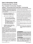
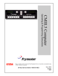
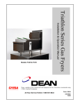
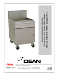
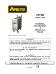
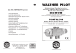
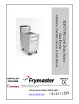
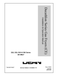
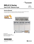
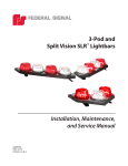
1
YSCFC24 Series Flatbottom Gas Fryers
Installation & Operation Manual
Model YSCFC24 Systems
with Built-In Filtration
Frymaster/Dean, a member of the Commercial Food Equipment Service Association,
recommends using CFESA Certified Technicians.
24-Hour Service Hotline 1-800-551-8633
PRINTED IN THE USA
AUGUST 2007
*8196352*
Please read all sections of this manual and retain for future reference.
This product has been certified as commercial cooking equipment and MUST be installed by
professional personnel as specified. Installation, maintenance and repairs should be performed
by your FRYMASTER FACTORY AUTHORIZED SERVICE CENTER.
DANGER
Do not store or use gasoline or other flammable vapors and liquids in the vicinity of this or any
other cooking appliance.
DANGER
Instructions explaining procedures to be followed MUST be posted in a prominent location in
the event the operator detects a gas leak. This information can be obtained from the local gas
company or gas supplier.
WARNING
Improper installation, adjustment, alteration, service or maintenance can cause property
damage, injury or death. Read the installation, operating and maintenance instructions
thoroughly before installing or servicing this equipment.
DANGER
Safe and satisfactory operation of your equipment depends on proper installation. Installation
MUST conform with local codes, or in absence of local codes, with the National Fuel Gas Code,
ANSI Z223.1; The Natural Gas Installation Code, CAN/CGA-B149.1; The Propane Installation
Code, CAN/CGA-B149.2; or The latest edition of the National Electric Code, N.F.P.A. 70.
NOTICE
IF, DURING THE WARRANTY PERIOD, THE CUSTOMER USES A PART FOR THIS ENODIS
EQUIPMENT OTHER THAN AN UNMODIFIED NEW OR RECYCLED PART PURCHASED
DIRECTLY FROM FRYMASTER/DEAN, OR ANY OF ITS AUTHORIZED SERVICE CENTERS,
AND/OR THE PART BEING USED IS MODIFIED FROM ITS ORIGINAL CONFIGURATION, THIS
WARRANTY WILL BE VOID. FURTHER, FRYMASTER/DEAN AND ITS AFFILIATES WILL NOT BE
LIABLE FOR ANY CLAIMS, DAMAGES OR EXPENSES INCURRED BY THE CUSTOMER WHICH
ARISE DIRECTLY OR INDIRECTLY, IN WHOLE OR IN PART, DUE TO THE INSTALLATION OF
ANY MODIFIED PART AND/OR PART RECEIVED FROM AN UNAUTHORIZED SERVICE CENTER.
DANGER
The crumb tray in fryers equipped with a filter system must be emptied into a fireproof container
at the end of frying operations each day. Some food particles can spontaneously combust if left
soaking in certain shortening material. Additional information can be obtained in the filtration
manual included with the system.
NOTICE
The Commonwealth of Massachusetts requires any and all gas products to be installed by a
licensed plumber or pipe fitter.
DANGER
The front ledge of the fryer is not a step. Do not stand on the fryer. Serious injury can result
from slips or contact with the hot oil.
WARNING
Drawings and photos used in this manual are intended to illustrate operational, cleaning and
technical procedures and may not conform to on-site management operational procedures.
WARNING
No structural material on the fryer should be altered or removed to accommodate placement of
the fryer under a hood. Questions? Call the Frymaster/Dean Service Hotline at 1-800-551-8633.
This equipment is to be installed in compliance with the basic plumbing code of The Building
Officials and Code Administrators International, Inc. (BOCA) and the Food Service Sanitation
Manual of the Food and Drug Administration.
COMPUTERS
FCC
This device complies with Part 15 of the FCC rules. Operation is subject to the following two conditions:
1) This device may not cause harmful interference, and 2) This device must accept any interference
received, including interference that may cause undesired operation. While this device is a verified Class
A device, it has been shown to meet the Class B limits.
CANADA
This digital apparatus does not exceed the Class A or B limits for radio noise emissions as set out by the
ICES-003 standard of the Canadian Department of Communications.
Cet appareil numerique n’emet pas de bruits radioelectriques depassany les limites de classe A et B
prescrites dans la norme NMB-003 edictee par le Ministre des Communcations du Canada.
DANGER
THIS PRODUCT CONTAINS CHEMICALS KNOWN TO THE STATE OF CALIFORNIA TO CAUSE
CANCER AND/OR BIRTH DEFECTS OR OTHER REPRODUCTIVE HARM.
Operation, installation, and servicing of this product could expose you to airborne particles of
glasswool or ceramic fibers, crystalline silica, and/or carbon monoxide. Inhalation of airborne
particles of glasswool or ceramic fibers is known to the State of California to cause cancer.
Inhalation of carbon monoxide is known to the State of California to cause birth defects or other
reproductive harm.
WARNING
Do not bang fry baskets or other utensils on the fryer’s joiner strip. The strip is present to seal
the joint between the fry vessels. Banging fry baskets on the strip to dislodge shortening will
distort the strip, adversely affecting its fit. It is designed for a tight fit and should only be
removed for cleaning.
Y24G Series Flatbottom Gas Fryers
INSTALLATION & OPERATION MANUAL
TABLE OF CONTENTS
Page #
1.
DESCRIPTION AND SPECIFICATIONS
1-1
2.
PRE-INSTALLATION
2-1
3.
INSTALLATION INSTRUCTIONS
3-1
4.
INITIAL STARTUP
4-1
5.
DAILY OPERATION
5-1
6.
PREVENTATIVE MAINTENANCE
6-1
7.
TROUBLESHOOTING
7-1
YSCFC24 SERIES FLATBOTTOM GAS FRYERS
CHAPTER 1: DESCRIPTION AND SPECIFICATIONS
The YSCFC24 Series gas fryers are energy-efficient, gas-fired units, design-certified by the
American Gas Association and the National Sanitation Foundation, and manufactured to their basic
performance and application specifications. All units are shipped completely assembled, with all
accessories packed inside the frypot. All units are adjusted, tested, and inspected at the factory
prior to crating for shipment.
NOTE
After uncrating, immediately inspect the equipment for visible
signs of shipping damage. If such damage has occurred, do not
refuse shipment, but contact the shipper and file the appropriate
freight claims.
1.1 OPERATING CONTROLS
Each unit is shipped with a solid-state electronic thermostat controller. The controller is mounted
inside the cabinet. The controller contains an automatic melt cycle which activates the main burner
"ON" for 4 seconds, then "OFF" for about 18 seconds, and is activated automatically every time the
frypot shortening temperature is less than 150°F (66°C). The melt cycle is used to heat solid
shortening properly.
Each unit is equipped with a control panel with two indicator lights and a power switch and reset
switch located in a control box inside the cabinet.
Note: Not equipped with oil-out switches. Boil-out is not allowed in any
YUM! location.
1.2 AUTOMATIC SAFETY FEATURES
YSCFC24 Series gas fryers come equipped with the following features:
A. High oil-temperature detection to shut off gas to the main burners through the solenoidactuated gas valve.
B. Combination gas valve includes built-in pressure regulator.
C. Pressure switch - air prover built into outlet duct shuts off power to the burners in the event
of blower failure.
D. Drain valve safety switch prohibits burner ignition if the valve is not completely closed.
DANGER
ALL FRYERS MUST BE CONNECTED ONLY TO THE TYPE OF GAS IDENTIFIED ON
THE RATING PLATE!
1-1
1.3 RATING PLATE
The rating plate can be found inside the fryer door. Information on this plate includes the model
and serial numbers, as well as BTU/hr output of the burners, outlet gas pressure in inches W.C.,
and configuration: natural or propane gas. Rating plate data is essential for proper unit
identification, communicating with the factory or requesting special parts and/or information.
1.4 SERVICE PROBLEMS
Call 1-800-551-8633 for the location of your nearest Factory Authorized Service Center. Always
have the model and serial numbers of your filter and fryer ready for when you speak to a
representative. A parts list is included in Chapter 8 of this manual. Customers may order parts
directly from their local Factory Authorized Service Center. Call 1-800-551-8633 for the location of
your nearest Factory Authorized Service Center. Factory address and phone numbers are on the
rear cover of this manual.
1.5 AFTER PURCHASE
In order to improve service, have the following chart filled in by the Frymaster Authorized Service
Technician who installed this equipment.
Authorized
Service
Technician/FASC
Address
Telephone/Fax
Model Number
Serial Number
Gas Type
1.6 ORDERING PARTS
Customers may order parts directly from their local factory authorized service center. For this
address and phone number, contact your factory authorized service center or call the Frymaster
Service Hotline phone number, 1-800-551-8633.
To speed up your order, provide the model number, serial number, gas type, part needed, item part
number (if known), and quantity needed.
1-2
1.7 COMPUTER INFORMATION
This equipment has been tested and found to comply with the limits for a Class A digital device,
pursuant to Part 15 of the FCC rules. While this device is a verified Class A device, it has been
shown to meet the Class B limits. These limits are designed to provide reasonable protection
against harmful interference when the equipment is operated in a commercial environment. This
equipment generates, uses and can radiate radio frequency energy and, if not installed and used in
accordance with the instruction manual, may cause harmful interference to radio communications.
Operation of the equipment in a residential area is likely to cause harmful interference in which case
the user will be required to correct the interference at their own expense.
The user is cautioned that any changes or modifications not expressly approved by the party
responsible for compliance could void the user's authority to operate the equipment.
If necessary, the user should consult the dealer or an experienced radio and television technician
for additional suggestions.
The user may find the following booklet prepared by the Federal Communications Commission
helpful: "How to Identify and Resolve Radio-TV Interference Problems". This booklet is available
from the U.S. Government Printing Office, Washington, DC 20402, Stock No. 004-000-00345-4.
1.8 SAFETY INFORMATION
Before attempting to operate your unit, read the instructions in this manual thoroughly.
Throughout this manual, you will find notations enclosed in double-bordered boxes similar to the
ones below.
CAUTION
CAUTION boxes contain information about actions or conditions that may cause or result in a
malfunction of your system.
WARNING
WARNING boxes contain information about actions or conditions that may cause or result in
damage to your system, and which may cause your system to malfunction.
DANGER
DANGER boxes contain information about actions or conditions that may cause or result in injury
to personnel, and which may cause damage to your system and/or cause your system to
malfunction.
1-3
1.9 SERVICE PERSONNEL
1.9.1 Definitions
A. Qualified and/or Authorized Operating Personnel
1.
Qualified/authorized operating personnel are those who have carefully read the information
in this manual and have familiarized themselves with the equipment functions, or have had
previous experience with the operation of equipment covered in this manual.
B. Qualified Installation Personnel
1.
Qualified installation personnel are individuals, or firms, corporations, or companies, which,
either in person or through a representative are engaged in and are responsible for the
installation of gas-fired appliances. Qualified personnel must be experienced in such work,
be familiar with all gas precautions involved, and have complied with all requirements of
applicable national and local codes.
C. Qualified Service Personnel
1.
Qualified service personnel are those who are familiar with Frymaster equipment and have
been authorized by Frymaster to perform service on Frymaster equipment. All authorized
service personnel are required to be equipped with a complete set of service parts manuals
and stock a minimum amount of parts for Frymaster equipment. A list of Frymaster Factory
Authorized Service Centers (FASCs) was included with the fryer when shipped from the
factory. Failure to use qualified service personnel will void the Frymaster warranty on
your equipment.
1-4
YSCFC24 SERIES FLATBOTTOM GAS FRYERS
CHAPTER 2: PRE-INSTALLATION
2.1 GENERAL
A. Installation of any gas-fired equipment should be performed by qualified personnel.
B. A manual gas shut-off valve must be installed in the gas supply line between the
appliance(s) and the main gas supply for safety and ease of future service.
2.2 CLEARANCES
The appliance area must be kept clear of all combustibles. Each unit is design-certified for the
following installations:
1. Commercial use only (not for household use).
2. For installation on a combustible floor when equipped with the factory supplied 5" casters (6"
work height).
3. Areas with a minimum clearance of 6" side, 6" rear and 6" from the floor for combustible
construction. YSCFC24 Series flatbottom gas fryers must be installed with the casters provided.
Locking casters should be installed on the front (cook side) of the fryer.
2.3 STANDARDS
Installation must be accomplished in accordance with all applicable state and local codes, with
special attention to the following standards:
A. The fryer and its individual shut-off valve must be disconnected from the gas supply piping
system during any pressure testing of that system at pressures in excess of 1/2 PSI.
B. The fryer must be isolated from the gas supply piping system by closing its individual
manual shut-off valve during any pressure testing of the gas supply piping system as
pressures equal to or less than 1/2 PSI.
C. National Fuel Gas Code
ANSI Z-223.1-1988 (or latest edition)
American Gas Association
1515 Wilson Boulevard
Arlington, VA 22209
D. National Electrical Code
ANSI/NFPA #70-1984 (or latest edition)
American National Standards Institute
1430 Broadway
New York, NY 10018
2-1
2.3 STANDARDS (cont.)
E. NFPA Standards #96 and #211 (latest edition)
National Fire Protection Association
470 Atlantic Avenue
Boston, MA 02110
WARNING
Local building codes will usually not permit a deep fat fryer with
an open tank of hot oil to be installed immediately next to an
open flame of any type, whether a broiler or the open burner of a
range. Check local codes before beginning installation.
2.4 AIR SUPPLY & VENTILATION
The area around the appliance must be kept clear to avoid airflow obstruction of
combustion and ventilation air as well as for ease of maintenance and service. Never use
the interior of the fryer cabinet for storage.
A. Means must be provided for any commercial, heavy-duty cooking appliance to exhaust
combustion wastes to the outside of the building. It is essential that a deep fat fryer be
located under an approved exhaust hood or that an exhaust fan be provided in the wall
above the unit, as exhaust gas temperatures are in the vicinity of 450°F-600°F (232-343°C).
Exhaust hoods and air conditioning systems can produce slight air drafts in the room, which
can interfere with pilot or burner performance. Air movement patterns should be defined
during installation. If pilot or burner problems arise or persist, alteration of air movement
patterns will be required.
B. Do not place the flue outlet of the fryer directly into the plenum of the hood; fryer gas
combustion will be affected.
C. Exhaust temperatures, in addition to the open tank of hot oil, make the storage of anything
on shelving over or behind the fryer unsafe.
D. Filters and drip troughs should be part of any industrial hood. Consult local codes before
installing an industrial hood.
2.5 ALTITUDE
The input rating (BTU/hr) of YSCFC24 Series fryers is rated for elevations up to 2,000 feet (610
Meters). For elevations above 2,000 feet (610 Meters), the rating should be reduced four percent
for each additional 1,000 feet (305 Meters) above sea level.
2-2
YSCFC24 SERIES FLATBOTTOM GAS FRYERS
CHAPTER 3: INSTALLATION INSTRUCTIONS
3.1 UNPACKING
Check that the container is upright. Use outward prying - no hammering - to remove the carton.
Inspect the fryer(s) for visible damage. If such damage has occurred, do not refuse shipment, but
contact the carrier and file the appropriate freight claims.
FRYMASTER FRYERS EQUIPPED WITH LEGS ARE FOR PERMANENT
INSTALLATION. FOR MOVEABLE OR PORTABLE INSTALLATION, FRYMASTER
OPTIONAL EQUIPMENT CASTERS MUST BE USED.
QUESTIONS? CALL 1-800-551-8633.
3.2 CASTERS
Casters should be installed near where the appliance is to be used. After unpacking, raise the unit
approximately 12 inches to attach casters to the couplings. Lower the fryer gently to prevent
damaging the casters and internal mounting hardware. Use a pallet lift jack if available, when
installing casters. Systems ordered with optional casters come with casters installed.
3.3 POSITIONING
Do not push against any of the edges of the unit to adjust its position. Lift fryer slightly and place it
where it is to be installed. Although all metal parts are deburred during manufacture, accidents
could occur if the fryer (or a lineup) should move suddenly when being pushed into position by
hand. Pushing a unit (rather than using a lift jack) also increases the probability of bending the leg
spindles or the internal coupling connectors.
3.4 LEVELING
A. A spirit level should be placed across the top of the fryer and the unit leveled both front-toback and side-to-side (side-to-side adjustment is not possible on units equipped with
casters). Erratic burner combustion, inefficient unit operation and oil-drainage problems are
some of the problems caused by unleveled fryers. In addition, units may not match up
properly in a multi-unit battery.
B. If the floor is smooth and level, minor height adjustments can be made with the screw
adjustment on each leg. Adjust to the high corner and measure with the spirit level. Fryers
equipped with casters have no level adjustment options. The floor area where casterequipped units are installed must be level.
3-1
3.5 GAS CONNECTION
The gas supply (service) line must be the same size or greater than the inlet line of the appliance.
YSCFC24 Series gas fryers use a 3/4" NPT (Schedule 40) inlet; however, the gas supply lines must
be sized to accommodate all the gas-fired equipment that may be connected to that supply.
Consult your contractor, gas company or supplier, or other authorized agent for inspection and
installation. Sealant on all pipe joints must be resistant to LP gas.
3.5.1 Manual Shut-off Valve
The manual shut-off valve must be installed in the gas service line ahead of the appliance in the
gas stream and in a position where it can be reached quickly in the event of an emergency.
3.5.2 Gas Pressure Regulation
All commercial cooking equipment must have a pressure regulator on the incoming service line for
safe and efficient operation, since service pressure may fluctuate with local demand. External
regulators are not required on YSCFC24 Series gas fryers as the pilot safety control valve regulates
gas pressure. If the incoming pressure is in excess of 1/2" PSI (3.45 kPa), a step-down regulator
will be required.
Check burner manifold pressure with a manometer. Natural gas units require 4" W.C. gas pressure
and propane (LP) units require 11" W.C. gas pressure. If a pressure regulator vent line is installed,
it should be vented to the outside of the building in accordance with local codes, or ANSI Z223.1 (or
current revision).
Disconnect the fryer/individual shut-off valve from the main gas supply when pressure testing
systems in excess of 1/2" PSI (3.45 kPa). When pressure-testing systems equal to or less than 1/2"
PSI (3.45 kPa), isolate the fryer by closing the manual control valve prior to testing.
3.5.3 Gas Valve/Orifice Configuration
YSCFC24 Series gas fryers can be connected to either natural or propane gas, depending on the
configuration. The safety control valve and orifices are installed at the factory for the appropriate
gas. If the gas valve and/or orifices require adjustment or conversion in the field, only authorized
service personnel with proper test equipment should make the adjustments or conversion.
3.5.4 Rigid Connections
YSCFC24 Series gas fryers come as single units or in multi-unit batteries. Inspect all installersupplied gas-intake pipe(s) for dirt, metal dust and other foreign material. Use compressed air to
clear foreign material from supply piping before installing into a service line. Failure to do this can
result in clogged orifices and gas valve damage when gas pressure is applied.
All connections must be sealed with a joint compound suitable for LP gas, and all connections must
be tested with a soapy solution before lighting any pilots. DO NOT USE AN OPEN FLAME TO
CHECK FOR LEAKS! Detecting gas leaks with an open flame is not only dangerous, but will often
miss small leaks that a soapy solution would detect.
3-2
3.5.5 Flexible Couplings, Connectors
If the unit is to be installed with flexible couplings and/or quick-disconnect fittings, the installer must
use a heavy-duty, AGA design-certified commercial flexible connector. The connector must be at
least 3/4" NPT (with suitable strain reliefs) in compliance with the Standard for Connectors for
Movable Gas Appliances, ANSI Z21.69-1987 (or latest edition). Quick-disconnect devices must
comply with the Standard for Quick-Disconnect Devices for Use with Gas Fuel, ANSI Z21.41-1989
(or latest edition). DOMESTIC CONNECTORS ARE NOT SUITABLE!
If multi-unit batteries are installed on casters, the same ANSI Standards apply. In addition, some
means must be provided to limit the movement of the appliances without depending on the
connectors or associated piping.
3.6 ELECTRICAL CONNECTIONS
The wiring diagram is attached to the inside of the fryer door. Wiring diagrams are also included in
this manual for reference. Always consult the wiring diagram mounted on the fryer when
troubleshooting or repairing the fryer. YSCFC24 Series gas fryers require 120 volts, and are
equipped with a 16-3 SJT grounded flexible power cord for direct connection to a 120-volt power
supply. Amperage for each unit depends on the accessories supplied with the unit.
WARNING
(Electrical Grounding Instructions)
This appliance is equipped with a three-prong (grounding) plug for your protection
against shock hazard, and should be plugged directly into a properly grounded
three-prong receptacle. Do not cut, remove, or otherwise bypass the grounding
prong on this plug!
3-3
3.7 SYSTEM INSTALLATION INSTRUCTIONS
1. This system consists of a 2424G fryer with a
built-in filter and an additional fryer that will
be attached to it. The additional fryer may
be a 24G, an 1824G or a 2424G. If the
additional fryer is an 1824G, the 18-inch
frypot must be in the outside position, as
shown in the illustration below.
These frypots must mate.
These frypots must mate.
24
18
24
24
Filter Unit
24
Figure
1. Retainer
latches
securing
Figure
1. Remove
the filter
pan byfilter
pan.
pulling it out from underneath the
fryer.
18
The 24-inch frypots must mate with each other.
18-inch frypots, if present, must always be to
the outside of the battery.
2. Prior to removing the fryers from their
pallets, open the doors of the 2424G with the
filter remove the filter pan (Fig. 1). Remove
the fryers from the pallets by lifting them up
and over the pallet supports. Avoid damage
to the casters and caster support bases
when lifting and placing fryers.
All connection hardware (bolts, nuts, etc.) is
included in the shipping bag.
3. Remove the upper and lower back panels (Fig.
2, arrows) of the cabinets to be joined. Set the
screws and back panels aside for later
reassembly. Place a rubber boot on the end of
the filter unit's drainpipe.
Figure 2. Remove all of the screws at
each location to remove cabinet backs.
4. Position the cabinets within 6 inches of each
other, close to the area where they will be
installed. Do not push the cabinets together at
this time. Connect the wires exiting the
cabinets to be joined (Fig. 3). The 1824G oilreturn switches will not work if these wires are
not connected.
5. Slowly push the two systems together. Adjust
the front casters to align the cabinets vertically.
Ensure the drainpipe on the connecting unit and
the rubber boot on the main unit are aligned.
The drainpipe should slide into the rubber boot;
do not push the drainpipe all of the way in. Feed
the yellow and red wire connections evenly
through each cabinet wire hole as the cabinets
are pushed together. Ensure the wire
connections go inside the wireway, and are not
pinched between the cabinets.
3-4
Figure 3. Wires connecting oil return
switches.
3.7 SYSTEM INSTALLATION INSTRUCTIONS (CONT.)
6. With the cabinets together, carefully slide the
drainpipe halfway into the rubber boot.
Connect the drain-flush and oil-return
flexlines (Fig. 4, arrow). Align the cabinet
connection holes, front and back (Fig. 4,
circle).
7. Insert bolts and install nuts loosely (Fig. 5,
arrows). Do not tighten bolts at this time.
8. When the two cabinets are properly aligned,
tighten the cabinet connection nuts and bolts
at the front and back. At the fryer front:
The bolts are located at the bottom front of
the connecting wall of the fryer and at the
control box. At the fryer back: The bolts are
located at the just inside the cabinet near the
cabinet connection holes, and at the top
inside the connecting wall of the flue box.
9. Reinstall back panels removed at the
beginning of system assembly. Ensure
panels are properly aligned, then install and
tighten the screws. Install the joiner strip
where fryer cabinets are connected.
Figure 4. Connect flexlines and align
cabinet connection holes.
Figure 5. Insert bolts, but do not tighten.
10. Connect the oil-return heater-tape harness
(6-pin connector) at the bottom back of the
fryer (Fig. 6, arrows). Failure to do so will
result in clogged return lines after the first
filtering session.
Figure 6. Connect heater-tape harness.
3-5
3.7 SYSTEM INSTALLATION INSTRUCTIONS (CONT.)
11. Prior to performing start-up, ensure the drainpipe connected during assembly is not blocking
either frypot drain. Shine a flashlight into the drains. The illustration below shows from left to
right, an unblocked drain, a partially blocked drain, and a completely blocked drain. If partially
or completely blocked, loosen the drain slip-nuts and reposition the drain tube. Both drains
should appear as the left-most picture below.
Drain
unblocked.
Drain partially
blocked.
Drain completely
blocked.
12. Reinstall filter system after fryer start-up has been performed (boil-out, burner adjustment, etc.)
NEVER ALLOW WATER OR BOILOUT SOLUTION INTO FILTER SYSTEM.
13. Follow the filtration instructions for the UFF filter and return the oil to each of the fryers in the
system. Check the oil return and drain lines for leaks. After the filtration system check is
complete, discard the oil and filter paper (if a filter screen is used, thoroughly wash the
assembly, dry completely and return to the pan). The frying system is ready for operation.
14. If the unit is supplied with an Over-The-Fryer Crumb Dump, install in accordance with the
illustration below.
Align the crumb dump side
with the slot in the deflector
during installation.
On fryer back, remove the back
panel screws (2) corresponding
to the tab holes on the crumb
dump.
FRONT
Set the crumb dump frame over the flue
deflector and align the screw holes.
Ensure the crumb dump deflector sits over
the top of the flue deflector. Secure the
crumb dump to the deflector with the
screws and nuts provided.
BACK
Replace the screws removed from the back panel prior to
crumb dump installation. Ensure all screws are properly
tightened. Install the crumb dump insert and return the
fryer to operation.
3-6
YSCFC24 SERIES FLATBOTTOM GAS FRYERS
CHAPTER 4: STARTUP AND OPERATING PROCEDURES
4.1 CLEANING
Note: All procedures should be performed as instructed in the current company Operations
Manual. In the absence of the company Operations Manual, the following procedures are
offered as a temporary solution.
New units are wiped clean with solvents at the factory to remove dirt, oil, and grease remaining
after the manufacturing process, and then coated with light oil. Prior to first use, boil out the frypot
(remove temperature sensor guard prior to cleaning frypot) as outlined in Section 4.4.1, Boil-Out
Procedure. Wash any accessories shipped with the unit in hot, soapy water to remove remaining
residue. Rinse the frying utensils with a solution of vinegar and water (1 pint vinegar to 1/2 gallon of
hot water) to neutralize any soap residue, then rinse with clean water and thoroughly dry all
surfaces.
Ensure the sensor probe guard is replaced after cleaning to protect the sensor probe and high-limit
probe (Figure 1).
Sensor Probe Guard
High-Limit/Temperature
Probe location
Frypots without probe-mounting
hardware: Ensure probe tip is 1/8" from
frypot bottom for proper temperature sensing.
Oil-Return Port (built-in filter
equipped systems only)
Frypot Bottom
Frypot Drain Plug
Frypots with probe-mounting hardware: No
special adjustment is required. Temperature probe
bulb will contact oil-return shield in built-in filtrationequipped frypots.
Figure 1: Sensor probe guard, frypot drain plug and high-limit/sensor probe location.
4-1
4.2 INITIAL STARTUP
YSCFC24 Series gas fryers are tested, adjusted, and calibrated before leaving the factory.
Adjustments to assure proper operation may be necessary upon installation to meet local
conditions, low gas pressure, differences in altitude, variations in gas characteristics and to correct
possible problems caused by rough handling or vibrations during shipment. Gas component
adjustments after receiving the fryer should be performed by authorized service personnel.
Gas component adjustments are the responsibility of the customer and/or dealer and are not
covered by the Frymaster warranty.
CAUTION
IF THE MAIN BURNERS ARE OPERATED WITH THE FRYPOT EMPTY, THE FRYPOT
WILL BE DAMAGED.
IF THE FRYPOT IS DAMAGED DUE TO INCORRECT OPERATION, SUCH AS
HEATING AN EMPTY FRYPOT OR WHOLE BLOCKS OF SHORTENING, ALL
APPLICABLE WARRANTIES WILL BE VOIDED.
NOTE: In KFC co-branded locations do not use water for initial startup. Use
shortening or oil only.
Pilot Light or re-light procedure:
1. Turn the manual shut-off valve "OFF" on the incoming service line.
2. Turn the Thermatron dial to the lowest setting.
3. Turn the gas valve dial to "OFF" and wait 5 minutes before lighting pilot.
4. Fill the frypot with oil or water (for testing). Fill to the appropriate oil level line scribed in the
back of the frypot (see store operational procedures for appropriate fill level).
NOTE: In KFC co-branded locations, oil must be used in place of water for burner testing.
5. Open the manual shut-off valve on the incoming service line.
6. Apply a lit match or taper to the pilot burner orifice.
7. Turn the gas valve dial to "PILOT". Depress and hold until the pilot stays lit (approximately 1
minute).
8. Turn the Thermatron controller to any "ON" setting and ensure the main burners ignite from the
pilot.
4-2
4.3 ELECTRONIC SPARK IGNITION
WARNING
NEVER USE A MATCH OR TAPER TO LIGHT THIS IGNITION SYSTEM!
1. Turn off the electric power.
2. Turn the gas valve dial to "OFF", wait 5 minutes, and then turn the dial to "ON".
3. Set the thermostat to the desired temperature. If the frypot is filled with water (non-KFC
co-branded locations), set thermostat to 200°F (93°C); if filled with oil, set thermostat to 350°F
(177°C).
4. Turn the fryer power switch on.
5. The blower motor should start and the fryer should light a few seconds later. After burner
ignition, the Thermatron controller controls the burner.
6. If the burner fails to light for whatever reason, a safety circuit will “lock out” the system. To clear
the lockout, turn the fryer off and follow steps 2–4 above.
7. If the flue exhaust fan fails, the gas control valve will shut off the gas supply.
4.4 ADJUSTING BURNERS
1. Fill the frypot with hot or cold water (non-KFC co-branded locations) to the top OIL LEVEL
line scribed in the back of the frypot. Main burner operation and initial controller calibration can
be checked during this step.
NOTE: In KFC co-branded locations, oil must be used in place of water for burner testing.
2. Set the Thermatron dial to 200°F (93°C), just below that of boiling water.
3. Turn the fryer power switch on. The blower will activate and the main burner will ignite.
4. Check the main burners and, if necessary, adjust the burner dampers at each burner (Figure 2,
Page 4-4) to obtain the best flame characteristics. An optimum flame should be blue at the
base, 2-½ - 3" in height, and have a reddish-white tip ¾ to 1" in height. To adjust, loosen the
screw of the air shutter, and open or close the shutter until the burner flame matches the
optimum flame description above. Tighten the shutter screw, and repeat for all burners. The
flame should be straight and not pulling to the rear of the fryer. If the flame is pulling to the rear,
inspect the main rear baffle for heat damage and replace if necessary.
5. The burners should shut off just at the water starts to boil.
6. When satisfied that the burners and controller are operating properly, drain the frypot of water
and dry thoroughly.
7. Immediately coat the frypot inside with oil to prevent rusting, or add new oil to the frypot if fryer
is ready for use.
4-3
4.4 ADJUSTING BURNERS (cont.)
Loosen screw to
adjust burner
damper for
optimum flame.
Figure 2: Burner damper adjustment on burner tubes.
4.5 FILLING THE VAT WITH SHORTENING
DANGER
NEVER MELT A SOLID BLOCK OF SHORTENING BY PLACING IT WHOLE INTO THE
FRYPOT. FRYPOT DAMAGE CAN OCCUR AND THE CHANCE OF FLASH-POINT
FIRE INCREASES.
1. Cut the block of shortening into small pieces and pack into the frypot bottom. Do not set a
whole block of shortening into the frypot. ENSURE THE BOTTOM OF THE FRYPOT IS
COMPLETELY COVERED WITH SHORTENING BEFORE TURNING UNIT ON. Continue
packing the frypot to the lower OIL LEVEL line scribed into the back of the frypot.
2. Turn the Thermatron controller to the desired temperature after the frypot is properly filled with
shortening. The burners will cycle in melt cycle mode until approximately 145°F (63°C), and
then remain on until setpoint temperature is attained. The “green” indicator light (heat indicator)
will cycle on and off at setpoint temperature.
4.6 FINAL PREPARATION
Before starting operation, turn the Thermatron controller to the desired shortening temperature, wait
for the temperature to stabilize, and then check with a high-quality immersion thermometer.
WARNING
NEVER MOVE A FRYER FILLED WITH HOT LIQUID.
DO NOT GO NEAR THE AREA DIRECTLY OVER THE FLUE OUTLET WHEN THE MAIN
BURNERS ARE OPERATING.
ALWAYS WEAR OIL-PROOF, INSULATED GLOVES WHEN WORKING WITH HOT OIL.
ALWAYS DRAIN HOT OIL INTO A METAL CONTAINER...HOT OIL CAN MELT
PLASTIC BUCKETS AND SHATTER GLASS CONTAINERS.
4-4
YSCFC24 SERIES FLATBOTTOM GAS FRYERS
CHAPTER 5: DAILY OPERATION/FILTRATION
5.1 OPENING
At opening, check the fryer for:
1. Combination or main gas valve "OFF".
2. Power Switch "OFF" (If so equipped).
For lighting the fryer, see Section 4.2 (Section 4.3 if equipped with Electronic Ignition).
5.2 GENERAL OPERATIONS STATEMENT
See the company Operations Manual for operating instructions prior to using the YSCFC24
Series gas fryer. Operating instructions in this chapter are intended for temporary use as a
guide in absence of the company Operations Manual.
5.3 FILTERING
Shortening should be filtered at least daily, or more frequently if cooking is heavy. This assures the
longest life possible for the shortening, imparts a better flavor to the product and minimizes flavor
transfer. To ensure shortening quality, filtering and daily maintenance should be performed
according to company Operations Manual.
WARNING
LEAVE FRYER OFF FOR A MINIMUM OF 10 MINUTES PRIOR TO FILTERING TO
ALLOW FRYPOT HEAT TO DISSIPATE. FRYPOT DAMAGE CAN OCCUR IF THE
SHORTENING IS DRAINED IMMEDIATELY AFTER TURNING FRYER OFF.
WARNING
WHEN OPERATING THE FILTRATION SYSTEM, NEVER LEAVE THE FILTER
UNATTENDED. THE ACTION OF THE SHORTENING MOVING THROUGH THE HOSE
LINES COULD JOLT A FLEXIBLE RETURN HOSE OUT OF THE FILTER PAN,
SPRAYING HOT SHORTENING AND CAUSING SEVERE BURNS.
DANGER
THE CRUMB TRAY IN FRYERS EQUIPPED WITH A FILTER SYSTEM MUST BE
EMPTIED INTO A FIREPROOF CONTAINER AT THE END OF FRYING OPERATIONS
EACH DAY. SOME FOOD PARTICLES CAN SPONTANEOUSLY COMBUST IF LEFT
SOAKING IN CERTAIN SHORTENING MATERIAL.
5-1
5.4 FILTER PREPARATION
1. Assemble the filter pan, ensuring all components are clean and dry. When assembling the filter
pan, follow company Operations Manual, or the following in absence of company instructions:
2. Remove filter-pan lid.
3. Place the filter leaf assembly in the bottom of
the filter pan. Ensure the pick-up tube goes
to the right side of the pan (when viewed
from front).
4. Sprinkle the prescribed amount of filter
powder over the filter leaf assembly, ensuring
even, overall coverage.
5. Place the crumb tray inside filter pan, in the
proper position.
Filter pan assembly.
Applying filter powder to screen.
Placing the crumb screen.
5-2
5.4 FILTER PREPARATION (cont.)
6. Replace the filter pan lid. Ensure pick-up
tube emerges through hole in pan lid.
Ensure filter system hose connection is
properly attached to the filter leaf connection
prior to activating filter pump. See Section
5.5 for filtering instructions.
Ensure pick-up
tube emerges
through hole in
pan lid.
5.5 FILTERING INSTRUCTIONS
WARNING
THE ON-SITE SUPERVISOR IS RESPONSIBLE FOR ENSURING THAT OPERATORS
ARE MADE AWARE OF THE INHERENT DANGERS OF OPERATING A HOT OIL
FILTER SYSTEM, PARTICULARLY ASPECTS OF OIL FILTRATION, DRAINING, AND
CLEANING OF THE FILTER.
The Flatbottom 24G Fryer System is equipped with the Under Fryer Filter (UFF). For optimum
system performance, do the following:
a. Use high-quality oil or shortening.
b. Filter daily or even more frequently if cooking is heavy. This assures the longest
possible oil life, imparts a better flavor to the product and minimizes flavor transfer.
c. Ensure oil-return lines are clear before turning off the filter pump and hang any flexible
lines up to drain. Solid shortening will solidify as it cools and clog the lines.
5-3
5.5 FILTERING INSTRUCTIONS (cont.)
A. Assemble tools for filtering. All except the squeegee are supplied with the filter starter kit:
1.
Squeegee- used to clean the frypot while filtering.
2.
Clean-Out Rod - long rod used to dislodge heavy debris in the drain tube.
3.
Filter Powder.
4.
Filter Leaf Assembly (Follow procedure in Section 5.4 for filter leaf installation).
CAUTION
USE ONLY APPROVED FILTER POWDER FOR BEST RESULTS. USE OF NONAPPROVED POWDER CAN CAUSE SYSTEM DAMAGE AND PREMATURE PUMP
FAILURE.
B. The following tools are not required, but are recommended to make filtering easier.
1.
Measuring Cup - used to measure filter powder.
2.
Stainless Steel Crumb Scoop - for removing debris.
C. Always wear oil-resistant, insulated gloves and/or protective gear when working with hot oil.
D. Put on protective gear.
E. Pull the UFF filter pan out from fryer/ filter cabinet. Remove cover.
F. Remove filter leaf following instructions in Section 5.7.
G. Clean the filter pan thoroughly and
ensure all components are completely
dry.
H. Follow directions outlined in Section 5.4Filter Preparation, pages 5-2 – 5-3.
Ensure filter pan and all components are clean
and dry before installing filter leaf assembly
and crumb tray.
5-4
5.6
FILTER OPERATION
Oil-return
(yellow)
Flush
(blue)
Drain
(red)
YSCFC24 filter handle locations.
1. Turn the fryer OFF.
2. Immediately before draining, use correct straining method to collect large debris suspended in
oil.
3. Open the frypot drain valve by moving the red drain handle down.
YSCFC24 drain valve
and handle. Move the
red drain handle down
to open the valve,
draining the frypot into
the filter pan.
4. Squeegee the frypot sides to remove any debris. Use the clean-out rod to clear the drain if
necessary.
5-5
FILTER OPERATION (cont.)
5. Move the yellow oil-return handle from right to left to open
the oil-return line. The filter pump will activate.
NOTE: If the filter pump does not activate when the
oil-return handle is opened, allow the motor to cool at
least 45 minutes, then press the red reset button.)
6. Polishing: Leave the fryer drain valve open for
approximately 5 minutes and allow the oil to circulate
through the frypot, back into the filter. Polishing extends
oil life and improves cooking flavor.
Filter pump reset button, accessed
from the front of the fryer.
7. Close the fryer drain valve. The frypot will begin to fill.
8. Allow the filter to pump bubbles into the fryer for 15-30
seconds to clear the oil return lines.
9. Close the oil-return handle to shut filter pump off.
NOTE: If using solid shortening, ensure the oilreturn lines are clear before turning off the pump
motor. Hang all flexible hoses up to drain after
filtration is complete. Failure to due so increases
the likelihood of solidified shortening clogging the
lines.
10. Immediately empty the crumb tray into a fireproof
container after filtering is complete. Clean and dry the
filter pan and associated components as instructed in
Sections 5.4 and 5.5.
Allow the oil to bubble for 15-30 seconds
after the filter pan is empty to clear the oilreturn lines.
Empty contents of the crumb screen into a fireproof container
immediately after filtering is complete.
5-6
5.7 Disassembling/Assembling and Cleaning the Magnum Filter Leaf
YSCFC24 Series fryers with UFF filtration come equipped with a filter leaf, which eliminates the
need for filter paper. The filter leaf requires specific cleaning and assembly procedures. In the
absence of cleaning and disassembly/reassembly instructions shipped with the filter leaf, use the
following procedure:
2
4
1
1
3
5.7.1 Filter Leaf Disassembly/Assembly
Grasp the seal frame near each corner at the locking tab (
1
) and pull frame apart (see illustration
above). The seal frame will separate into two pieces. Separate the top and bottom screens
(
2
&
3
) and remove the grid (
4
). Assemble in reverse order.
5-7
5.7.2 Cleaning the Filter Leaf Assembly
Clean the two seal frame pieces, screens and grid using a good quality degreaser and hot water
from a spray nozzle. The groove in the seal frame pieces can be cleaned with the edge of a
Scotch-Brite or similar cleaning pad.
Allow all filter leaf components to air dry or thoroughly dry with paper towels.
5.8 CLOSING
When closing at night, filter the shortening as described in Sections 5.3–5.6. Cover open frypots of
oil with vat covers. Turn the power switch off and turn the control knob on the pilot safety valve to
"OFF".
5.8.1 Shutdown For Extended Periods
1. When shutting down for longer than overnight, drain the shortening, clean the frypot
thoroughly, and either discard the shortening or return it filtered to the frypot and cover it. If
shortening is not returned to the frypot, immediately coat the frypot with shortening to
prevent rust from forming.
2. Turn the manual valve on the incoming service line or combination gas valve to "OFF".
3. Disconnect any power cords from the wall sockets or turn off the circuit breakers.
SEE SECTION 4 FOR INITIAL STARTUP AND FRYER OPERATION
5-8
5.9 FILTER TROUBLESHOOTING
The problems and possible solutions covered are those most commonly encountered.
Pump won't
start.
Pump stops
during
filtering
process.
Motor is hot.
Pump stops
and motor is
cool.
Pump starts
and abruptly
stops.
y
y
y
y
Return valve not fully open.
Tripped circuit breaker.
Incorrect or no line voltage.
Failed return valve microswitch.
y
Allow motor to cool for at least 45 minutes and then
press thermal overload switch on motor. Also reset
the 7-amp circuit breaker.
y
Move filter handle to "OFF". Allow oil to cool then
empty pan. Verify filter leaf assembly is clean and
properly installed. Refill pan and restart process.
y
y
Reset thermal overload.
Verify wiring harness is properly connected; a
damaged harness should be replaced by an FASC.
Pump is blocked. Call FASC for service.
Filter pan suction tube is blocked. Use a thin,
flexible wire to unclog.
Motor or 24 VAC transformer failed; contact an
authorized service technician for service.
y
y
y
Pumping is
erratic.
Oil not being
returned to
frypot.
After filtering,
fryer does not
operate
properly.
y
y
y
Verify that filter leaf disconnect is properly attached
to filter system hose.
Verify that filter leaf is properly installed in filter pan.
y
Solidified oil or sediment is likely clogging the return
line. Clear line.
Clogged filter leaf.
y
Verify drain valve is fully closed.
5-9
YSCFC24 SERIES FLATBOTTOM GAS FRYERS
CHAPTER 6: PREVENTATIVE MAINTENANCE
Consult the company Operations Manual for cleaning and maintenance instructions.
Cleaning and maintenance instructions in this chapter are intended for temporary use as a
guide in absence of the company Operations Manual.
6.1 Daily Fryer Maintenance
Follow procedures in company Operations Manual.
6.2 Daily
Remove and wash all removable parts in hot, soapy water. Rinse in clean water and dry
thoroughly.
Clean all exterior surfaces of the fryer cabinet. DO NOT USE ABRASIVE CLEANSERS, STEEL
WOOL OR OTHER ABRASIVE MATERIAL TO CLEAN STAINLESS STEEL. See Section 6.5 for
stainless steel care.
Filter the oil and replace if necessary. Filter oil more frequently if use is heavy.
6.3 Monthly
Drain the frypot into the filter system or a metal container. Do not use plastic or glass containers for
hot oil.
Follow boil-out procedures (Non-KFC co-branded locations only) in the company Operations
Manual.
NOTE: In KFC co-branded locations, boil out is NOT ALLOWED. Use KFC approved
procedure.
Refill with oil as described in the company Operations Manual, or as described in Section 4.5,
Filling The Vat With Shortening.
6-1
6.4 Periodic
The fryer should be inspected and adjusted periodically by qualified service personnel as
part of a regular kitchen maintenance program.
Frymaster recommends that the fryer be inspected at least annually by a Factory Authorized
Service Technician as follows:
•
Inspect fryer cabinet inside and out, front and rear, for excessive oil build up and/or oil
migration. Verify that burners and associated components (i.e. gas valves, pilot assemblies,
ignitors, etc.) are in good condition and functioning properly. Inspect all gas connections for
leaks and ensure all connections are properly tightened.
•
Verify that temperature and high-limit probes are properly connected, tightened and functioning
properly.
•
Verify all component box components (i.e. computer/controller, relays, transformers, interface
boards, etc.) are in good condition and free from oil migration build up and other debris. Inspect
component box wiring and ensure all connections are tight and all wiring is in good condition.
Ensure all safety features (i.e. drain safety switches, reset switches, etc.) are present and
functioning properly.
•
Verify that the frypot is in good condition and free of leaks. Verify that frypot tube diffusers are
present and in good condition (i.e. no visible deterioration or damage).
•
Verify that all wiring and connections are tight and in good condition.
Built-in Filtration:
•
Inspect all oil-return and drain lines for leaks and verify that all connections are tight.
•
Inspect the filter pan for leaks and cleanliness. If there is a large accumulation of crumbs in the
crumb basket, advise the owner/operator that the crumb basket should be emptied into a
fireproof container and cleaned daily.
•
Verify that all O-rings and seals (including those on quick-disconnect fittings) are present and in
good condition. Replace O-rings and seals if worn or damaged.
6-2
6.4 Periodic (cont.)
•
Check filtration system integrity as follows:
−
With the filter pan empty, place each oil return handle, one at a time, in the "ON" position.
Verify that the pump activates and that bubbles appear in the cooking oil/shortening of the
associated frypot.
−
Close all oil return valves (i.e., place all oil return handles in the "OFF" position). Verify proper
functioning of each oil return valve by activating the filter pump using the lever on one of the oil
return handle microswitches. No air bubbles should be visible in any frypot.
−
Verify that the filter pan is properly prepared for filtering. After heating the oil to operating
temperature [~350°F (177°C)], turn fryer off and allow frypot to cool for 10 minutes. Drain the oil
into the filter pan and close the frypot drain valve. Place the oil return handle in the "ON"
position. Allow all cooking oil to return to the frypot (indicated by bubbles in the cooking
oil/shortening. Return the oil return handle to the "OFF" position. The frypot should refill in no
more than 2 minutes and 30 seconds.
To ensure good fryer health and a safe environment, the fryer should be checked and
adjusted periodically by qualified service personnel as part of a regular kitchen maintenance
program.
6.5 Stainless Steel Care
All stainless steel fryer cabinet parts should be wiped regularly with hot, soapy water during the day,
and with a liquid cleanser designed for stainless steel at the end of each day.
A. Do not use steel wool, abrasive cloths, cleansers or powders.
B. Do not use a metal knife, spatula or any other metal tool to scrape stainless steel!
Scratches are almost impossible to remove.
C. If it is necessary to scrape the stainless steel to remove any encrusted materials, soak the
area first to soften the deposit, then use a wood or nylon scraper only.
6-3
YSCFC24 SERIES FLATBOTTOM GAS FRYERS
CHAPTER 7: TROUBLESHOOTING
FACTORY APPROVAL MUST BE OBTAINED PRIOR TO ANY WARRANTY WORK BEING
DONE OR FRYMASTER CANNOT BE HELD RESPONSIBLE.
The following procedures must be performed by Factory Authorized Service Technicians, and are
provided as an aid to expedite troubleshooting and repair of YSCFC24 Series frying systems.
7.1 PILOT BURNER MALFUNCTIONS
PROBLEM
CORRECTIVE ACTION
Pilot will not ignite; no
evidence of gas at pilot
burner.
Ensure the combination gas valve is in PILOT position and that
gas is available at the control valve (check quick-disconnect
and/or gas-line connections for proper connection).
Pilot burner ignites but will
not remain lit when gas
knob is released.
Pilot flame may be adjusted incorrectly. Adjust flame to 1½"
high by turning pilot flow adjustment screw.
Pilot burner ignites
properly and burns
properly, but goes out
when the exhaust blower
comes on.
1.
Pilot flame may be adjusted too low, even though it
appears to be satisfactory. Re-adjust higher as described
earlier.
2.
Pilot flame may be adjusted too high and is on the verge
of blowing out. Re-adjust lower.
7-1
7.2 MAIN BURNER MALFUNCTIONS
PROBLEM
Main burner will not come
on even though air blower
is in operation; no gas
pressure at main burner.
Air blower is not operating,
although power is present
at the fryer.
Signs of excessive
frypot temperature;
Oil quickly becomes
discolored.
CORRECTIVE ACTION
1.
Check that the combination gas valve is ON.
2.
Check that the pilot is lit and is operating properly.
1.
Cooked product or other material may have fallen into the
flue and lodged in the blower wheel, preventing it from
turning. Clean out flue and blower wheel.
2.
Blower motor may have overheated and shut off. This
condition will correct itself when motor cools (20 minutes).
If problems with blower overheating persist, call for
service.
3.
If fryer is equipped with a Thermatron controller, the
temperature probe or the controller board may be
defective. Call for service.
1.
Check Thermatron controller; may be out of calibration.
Re-calibrate in accordance with instructions in Section
7.4.
2.
Shortening of inferior quality or used too long. Replace
with quality shortening.
7.3 INDICATOR LIGHTS
The fryer’s indicator lights serve a diagnostic purpose. All lights are lit when the fryer is working
properly. (The green light on the control panel will cycle on and off as the fryer calls for heat). Use
the following procedures to isolate problems indicated by light combinations. Lighting sequences
not listed are beyond the scope of operator correction; call an authorized service agent.
Turn the temperature dial to 400°F (204°C) to ensure the sensor will demand heat. Check all
indicator lights in the fryer cabinet and on the control panel. [Older units may have power and reset
switches with different colored lights (orange, amber, red, etc.). Substitute the light color of the old
switch with the respective "green light" switch in the following troubleshooting procedures. The
control panel light colors haven’t changed.]
7-2
7.3 INDICATOR LIGHTS (cont.)
When turning the power switch "ON" and resetting the safety (reset) switch, check for the following:
LIGHT INDICATION
GREEN LIGHT/POWER SWITCH IS
"ON"
PROBABLE CAUSE
1.
The drain valve is open.
2.
The drain switch is defective.
CORRECTIVE ACTION
GREEN LIGHT/SAFETY (RESET)
SWITCH IS "OFF"
1.
Ensure the drain valve is
completely closed, and then
turn the reset switch to "ON".
2.
If the light on the reset switch
does not turn on, contact a
Factory Authorized Service
Center for assistance.
1.
Check power source, power
cords and breaker. Ensure that
electricity is available to the
fryer.
2.
Replace fuse. If fuse continues
to blow, contact a Factory
Authorized Service Center.
3.
If fryer does not function after
resetting the reset switch,
contact a Factory Authorized
Service Center for assistance.
GREEN LIGHT/CONTROL PANEL IS
"OFF"
RED LIGHT/CONTROL PANEL IS
"OFF"
GREEN LIGHT/POWER SWITCH IS
"OFF"
1.
No power to fryer.
2.
Fuse is blown.
GREEN LIGHT/SAFETY (RESET)
SWITCH IS "OFF"
GREEN LIGHT/ CONTROL PANEL IS
"OFF"
RED LIGHT/CONTROL PANEL IS
"OFF"
7.4 THERMATRON CONTROLLER CALIBRATION
If the Thermatron controller requires adjustment, do the following:
1. Set Thermatron controller dial to the desired
shortening temperature and wait for the shortening
temperature to stabilize.
2. When shortening temperature reaches setpoint
(heat light will go off), check the temperature with a
high-quality immersion thermometer.
3. Loosen two knob setscrews and rotate the knob to
the correct temperature setting on the Thermatron
faceplate.
4. Check the temperature again with a high-quality
immersion thermometer to confirm that the setting
is correct.
5. Re-tighten both knob setscrews at the calibrated
position.
7-3
Loosen two setscrews in dial (arrows)
to recalibrate controller.
7.5 WIRING DIAGRAMS
7.5.1 YSCFC Wiring Diagram (with filter)
7-4
7.5.2 YSCFC Wiring Diagram (non-filter)
7-5
7.5.3 YSCFC24 Filter Wiring
7-6
THIS PAGE INTENTIONALLY LEFT BLANK
Frymaster, 8700 Line Avenue, PO Box 51000, Shreveport, Louisiana 71135-1000
Shipping Address: 8700 Line Avenue, Shreveport, Louisiana 71106
TEL 1-318-865-1711
PRINTED IN THE UNITED STATES
FAX (Parts) 1-318-688-2200
SERVICE HOTLINE
1-800-551-8633
FAX (Tech Support) 1-318-219-7135
AUGUST 2007