1
R
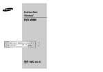
USER ’S MANUAL
SPS/A-Pattern Series
SPS/B-Pattern Series
SPS/C-Pattern Series
Electronically Controlled
Pattern Sewing Machine
(Electronic Control Part)
1) FOR AT MOST USE WITH EASINESS,
PLEASE CERTAINLY READ THIS MANUAL
BEFORE STARTING USE.
2) KEEP THIS MANUAL IN SAFE PLACE
FOR REFERENCE WHEN THE MACHINE
BREAKS DOWN.
SunStar CO., LTD.
MEE-101020
lity
a
u
tQ
Besst Pricevice
Be st Ser
Be
1. Thank you for purchasing our product. Based on the rich expertise and
experience accumulated in industrial sewing machine production, SUNSTAR
will manufacture industrial sewing machines, which deliver more diverse
functions, high performance, powerful operation, enhanced durability, and
more sophisticated design to meet a number of user’s needs.
2. Please read this user’s manual thoroughly before using the machine. Make
sure to properly use the machine to enjoy its full performance.
3. The specifications of the machine are subject to change, aimed to enhance
product performance, without prior notice.
4. This product is designed, manufactured, and sold as an industrial sewing
machine. It should not be used for other than industrial purpose.
R
SUNSTAR CO., LTD.
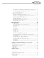
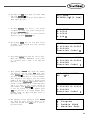
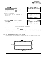
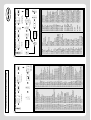
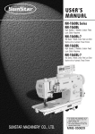
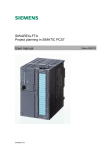
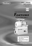
Organization of the Pattern S/M Model
SPS / A,B,C - 1 3 0 6 - H S - 1 0
Feeding Frame
Type
Series
(X)×10mm
Stitch Type
(Y)×10mm
Material Type
Sewing Area
Pattern Type
A : Belt Type
B : Direct Type
C : Separated upper and lower operation type
Sewing Type
1306 : X(130mm),
1310 : X(130mm),
1507 : X(150mm),
1811 : X(180mm),
2211 : X(220mm),
2516 : X(250mm),
3020 : X(300mm),
5030 : X(500mm),
5050 : X(500mm),
8050 : X(800mm),
Material Type
G:General Material
H:Heavy Material
Y(60mm)
Y(100mm)
Y(70mm)
Y(110mm)
Y(110mm)
Y(160mm)
Y(200mm)
Y(300mm)
Y(500mm)
Y(500mm)
Stitch
S:Standard Stitch
P:Perfect Stich
Feed Frame
10:Electronic
20:Pneumatic Monolithic Feeding Frame
22:Pneumatic Separately-Driven Feeding
23:Pneumatic Reverse Device
Attach/Separate Feed Frame
SPS/C-Series
01:Arm Lifting Type
02:Fixed Arm Type
CONTENT
1. Machine Safety Regulations …………………………………………………………… 6
2. I/O Board Dip Switch Setting ………………………………………………………… 9
3. Basic Operational Method ……………………………………………………………… 10
1) Name and roles of each key on operation unit………………………………………………
2) Name and description of each display contents on general operation mode ……………
3) Flow chart of general operation ………………………………………………………………
4) Work flow of pattern programming ……………………………………………………………
5) Operating after reading the patterns from USB flash drive ………………………………
6) Confirming the working pattern read from the USB flash drive …………………………
7) When a machine stops operating during sewing by the thread cut ………………………
8) Emergency stop during operation ………………………………………………………………
9) Winding the thread ……………………………………………………………………………
10) Safety Functions …………………………………………………………………………………
10
11
12
13
14
14
15
15
15
16
4. Applicable Operation ……………………………………………………………………… 19
1) Pattern Data Generation Function………………………………………………………………………… 19
1-1) Program example 1 : Generating the square pattern ………………………………… 19
1-2) Program example 2 : Generating the circle pattern ………………………………… 21
1-3) Program example 3 : Generating the double curve pattern ………………………… 23
1-4) Program example 4 : Pattern generation by using the second origin and pause …… 26
1-5) Zigzag shape selecting function to generate zigzag …………………………………… 30
2) Pattern Data Edit Function …………………………………………………………………… 32
2-1) One stitch movement function …………………………………………………………… 32
2-2) Partial movement function of pattern data …………………………………………… 33
2-3) A fix number of stitch delete function ………………………………………………… 35
2-4) Partial pattern data delete function …………………………………………………… 36
2-5) Partial stitch width changing function ………………………………………………… 38
2-6) Pattern partial copy function …………………………………………………………… 39
2-7) Pattern data inserting function…………………………………………………………… 41
3) Pattern Data Application Function …………………………………………………………… 43
3-1) Operation after reading pattern data from USB flash drive and moving the second
temporary start point……………………………………………………………………… 43
3-2) Program example 5 : Change of sewing speed within a pattern …………………… 44
3-2-1) Changing the sewing speed from an existing pattern data ………………… 44
3-2-2) Changing the sewing speed by making new pattern data…………………… 47
3-3) Program example 6 : Use of reversal ………………………………………………… 49
3-3-1) Pattern programming by using reversal………………………………………… 49
3-3-2) Adding the code to already programmed pattern …………………………… 52
3-4) Using the extension/reduction modes …………………………………………………… 54
3-5) Using the chain sewing mode …………………………………………………………… 56
3-6) Change/saving function of pattern data start point ………………………………… 58
3-7) Change/saving function of pattern 2nd original point………………………………… 60
3-8) Change/saving function of maximum pattern sewing speed and extension/reduction rate…… 61
3-9) Symmetrical shape creating function of pattern ……………………………………… 63
3-10) Condensed sewing stitch inserting function …………………………………………… 64
3-11) Automatic Back Tack(B/T) inserting function ……………………………………… 66
3-12) OverLap sewing stitch inserting function ……………………………………………… 67
3-13) Automatic insertion of thread trimmer code when deleting stitches ……………… 69
3-14) Setting-up reference point for zooming ………………………………………………… 70
3-15) Embroidery design call function ………………………………………………………… 72
3-16) JUKI Design Call………………………………………………………………………… 73
3-17) Sewing limit function …………………………………………………………………… 74
3-18) Quick origin search motion function for 1811 machines …………………………… 76
3-19) Setting origin search function of upper and lower shafts after finishing sewing
[only applied for SPS/C-Series]………………………………………………………… 77
3-20) Setting machine Head up or down function [Only for SPS/C-Series] …………… 78
3-21) Setting reverse rotation after trimming [Only applied for SPS/B/C-Series] ………… 79
3-22) Setting the angle of reverse rotation after trimming [Only applied for SPS/B/C-Series] …
3-23) Setting output port [Only applied for SPS/C-Series] ………………………………
3-24) Setting time delay when output port is being used [Only applied for SPS/C-Series] …
3-25) 3rd Thread Adjusting Device (TR3) Setting …………………………………………
3-26) Basic Clamp Position Setting ……………………………………………………………
4) Pattern Data General Function ………………………………………………………………
4-1) Checking and deleting the pattern number ……………………………………………
4-2) Making a copy the pattern to another number or diskette …………………………
4-3) Function to copy saved patternS from interior memory to USB flash drive ……
4-4) Pattern information displaying function …………………………………………………
4-5) Change of parameter related to general sewing ………………………………………
4-6) Initialization of parameter related to general sewing …………………………………
4-7) System program update ……………………………………………………………………
4-8) Confirmation for version of system program……………………………………………
4-9) Bobbin counter setting by design…………………………………………………………
4-10) Saving in the Internal Memory after Creating Pattern Designs……………………
80
81
84
85
88
89
89
90
91
92
93
94
95
96
97
99
5. High Operating Method …………………………………………………………………100
1) Understanding the function of machine test ………………………………………………… 100
1-1) Encoder test ………………………………………………………………………………… 100
1-2) Step motor-main shaft motor test (X-Y Main Test) ……………………………… 100
1-3) Main motor test …………………………………………………………………………… 101
1-4) Interrupt test ……………………………………………………………………………… 102
1-5) PWM test…………………………………………………………………………………… 102
1-6) LCD test …………………………………………………………………………………… 103
1-7) Keyboard test ……………………………………………………………………………… 104
1-8) Input 0 test ………………………………………………………………………………… 104
1-9) Input 1 test ………………………………………………………………………………… 105
1-10) Input 2 Test ……………………………………………………………………………… 106
1-11) Input 3 Test ……………………………………………………………………………… 106
1-12) Input 4 Test [Only applied for SPS/C-Series] ……………………………………… 107
1-13) Input 5 Test [Only applied for SPS/C-Series] ……………………………………… 107
1-14) Input 6 Test [Only applied for SPS/C-Series] ……………………………………… 108
1-15) Lower Shaft Encoder Test (Encoder1 Test) [Only applied for SPS/C-Series] ………… 109
1-16) Solenoid Test ……………………………………………………………………………… 109
1-17) Output 4 Test [Only applied for SPS/C-Series] …………………………………… 110
1-18) Output 5 Test [Only applied for SPS/C-Series] …………………………………… 111
1-19) Other output ports[only applied for SPS/C-Series] ………………………………… 111
1-20) Manual operation test of step motor (XY Jog Test) ……………………………… 112
1-21) Origin Test ………………………………………………………………………………… 112
1-22) Jump Test ………………………………………………………………………………… 113
1-23) Communication test between the main shaft board and the CPU/IO board (Async Test) …… 113
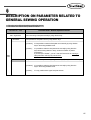
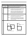
6. Description on Parameter Related to General Sewing Operation ………………115
1)
2)
3)
4)
5)
6)
7)
Function no. related pattern programming …………………………………………………… 164
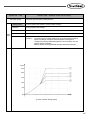
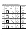
Pattern chart……………………………………………………………………………………… 166
Parameter number related to general sewing ………………………………………………… 167
Error list ………………………………………………………………………………………… 172
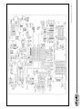
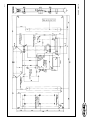
SPS/A/B/C-Series block diagram……………………………………………………………… 174
Table drawing …………………………………………………………………………………… 178
Basic Manual …………………………………………………………………………………… 179
7. Emergency Recovery………………………………………………………………………181
1) Emergency recovery when problems occur in flash memory ……………………………… 181
2) User's emergency self-restoration and operating program installation …………………… 182
8. Special Functions …………………………………………………………………………183
1) Auto Call Function ……………………………………………………………………………… 183
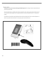
2) Design auto call through handy barcode……………………………………………………… 191
9. Parameter save function …………………………………………………………………194
1) Parameter Write ………………………………………………………………………………… 194
2) Parameter Read …………………………………………………………………………………195
1
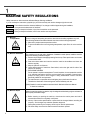
MACHINE SAFETY REGULATIONS
Safety instruction on this manual are defined as Danger, Warning and Notice.
If you do not keep the instructions, physical injury on the human body and machine damage might be occurred.
Danger : This indication should be observed definitely. If not, danger could be happen during the installation,
conveyance and maintenance of machines.
Warning : When you keep this indication, injury from the machine can be prevented.
Notice : When you keep this indication, error on the machine can be prevented.
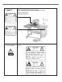
1-1) Machine
Transportation
Danger
1-2) Machine Installation
Warning
Those in charge of transporting the machine should know the safety regulations very well.
The following indications should be followed when the machine is being transported.
ⓐ More than 2 people must transport the machine.
ⓑ To prevent accidents from occurring during transportation, wipe off the oil on the machine
well.
The machine may not work well or breakdown if installed in certain places, Install the machine
where the following qualifications agree.
ⓐ Remove the package and wrappings starting from the top. Take special notice on the nails
on the wooden boxes.
ⓑ Dust and moisture stains and rusts the machine. Install an airconditioner and clean the
machine regularly.
ⓒ Keep the machine out of the sun.
ⓓ Leave sufficient space of more than 50cm behind, and on the right and left side of the
machine for repairing.
ⓔ EXPLOSION HAZARDS
Do not operate in explosive atmospheres. To avoid explosion, do not operate this machine
in an explosive atmosphere including a place where large quantities of aerosol spray
product are being used or where oxygen is being administered unless it has been
specifically certified for such operation.
ⓕ The machine were not provided with a local lighting due to the feature of machine.
Therefore the illumination of the working area must be fulfilled by end user.
[Refer] Details for machine installment are described in Mechanical Structure Manual
4. Machine Installment.
1-3) Machine Repair
Notice
When the machine needs to be repaired, only the assigned troubleshooting engineer educated at
the company should take charge.
ⓐ Before cleaning or repairing the machine, close down the motive power and wait 5
minutes till the machine is completely out of power.
ⓑ Not any of the machine specifications or parts should be changed without consulting the
company. Such changes may make the operation dangerous.
ⓒ Spare parts produced by the company should only be used for replacements.
ⓓ Put all the safety covers back on after the machine has been repaired.
6
1-4) Machine Operation
Warning
A(B) Pattern Series is made to sew patterns on fabrics and other similar material for
manufacturing.
Follow the following indications when operating the machine.
ⓐ Read through this manual carefully and completely before operating the machine.
ⓑ Wear the proper clothes for work.
ⓒ Keep hands or other parts of the body away from the machine operation parts(needle,
shuttle, thread take-up lever, and pulley etc.) when the machine is being operated.
ⓓ Keep the covers and safety plates on the machine during operation.
ⓔ Be sure to connect the earthing conductor.
ⓕ Close down the electric motive power and check if the switch is turned“off”before opening
electric boxes such as the control box.
ⓖ Stop the machine before threading the needle or checking after work.
ⓗ Do not step on the pedal when turning the power on.
ⓘ Do not connect several motors to the same concent.
ⓙ If possible, install the machine away from loud noise such as high frequency welding
machines
ⓚ Be careful when the upper feed plate comes down to press. Otherwise, the finger or hand
might be hurt at smacking.
[Warning]
Belt will crush or amputate finger or hand, keep cover in place before operating, turn off
power before inspecting or adjusting.
1-5) Devices for Safety
Notice
Safety label : It describes cautions during operating the machine.
Thread take-up cover : It prevents from any contact between body and take-up lever.
Belt Cover : It prevents from insertion of hands, feet or clothes by V-belt Motor.
Step motor cover : It prevents from accidents during rotation of step motors.
Label for specification of power : It describes cautions for safety to protect electric shock
during the motors’ rotation. (Voltage input / use Hz)
ⓕ Safety plate : It protects eyes against needle breaks.
ⓖ Finger guard : It prevent from contacts between a finger and needle.
ⓐ
ⓑ
ⓒ
ⓓ
ⓔ
ⓐⓑ
ⓒ
ⓓ
ⓕ
ⓖ
ⓐ
ⓔ
7
1-6) Caution Mark
Position
Caution mark is attached on the machine for safety.
When you operate the machine, observe the directions on the mark.
Position of Warning Mark
CAUTION
경 고
[View from the right-front]
Do not operate without finger guard and
safety devices. Before threading, changing
bobbin and needle, cleaning etc. switch off
main switch.
손가락 보호대와 안전장치 없이 작동하지
마십시오.
실, 보빈, 바늘교환시나 청소전에는 반드시 주
전원의 스위치를 꺼 주십시오.
WARNING
경 고
Hazardous voltage will cause injury.
Be sure to wait at least 360 seconds before
opening this cover after turn off main switch
and unplug a power cord.
고압 전류에 의해 감전될 수 있으므로 커버를
열 때는 전원을 내리고 전원 플러그를 뽑고 나
서 360초간 기다린 후 여십시오.
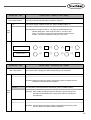
1-7) Contents of Marks
Caution
1)
CAUTION
경 고
Do not operate without finger guard
and safety devices. Before threading,
changing bobbin and needle, cleaning
etc. switch off main switch.
Warning
손가락 보호대와 안전장치 없이 작동하지 마
십시오.
실, 보빈, 바늘교환시나 청소전에는 반드시
주전원의 스위치를 꺼 주십시오.
2)
WARNING
경 고
Hazardous voltage will cause injury.
Be sure to wait at least 360 seconds
before opening this cover after turn
off main switch and unplug a power
cord.
고압 전류에 의해 감전될 수 있으므로 커버
를 열 때는 전원을 내리고 전원 플러그를 뽑
고 나서 360초간 기다린 후 여십시오.
8
2
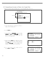
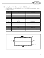
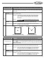
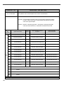
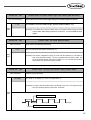
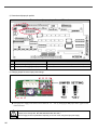
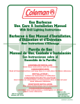
I/O Board Dip Switch Setting
This shows how to set up the dip switch(SW1) on the I/O board.
The figure above is based on the SPS/C-5050 I/O board.
The following describes each dip switch number.
SW1
1
Not used
2
Not used
3
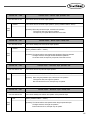
Main shaft motor type
ON : Direct drive
OFF : Belt type
4
If the main shaft motor is a d i r e c t d r i v e t y p e,
activate the serial communication witht he CPU card.
5
New I/O board setting
(After REV 21)
6
Not used
7
Distinction between integrated and non-integrated versions
ON : Non-integrated version setting
OFF : Integrated version setting
8
Not used
9
3
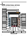
BASIC OPERATIONAL METHOD
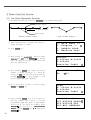
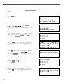
1) Name and Roles of Each Key on Operation Unit
POWER LED
Input of power
READY LED
Sewing available
condition
ERROR LED
Errors occurred
MODE KEY
Change of working
mode
SPEED KEY
Change of sewing speed
CODE KEY
Selection of function
code
LCD DISPLAY
Indication of contents
JUMP KEY
Input of jump code
NO. KEY
Input of pattern NO.
POINT-SET KEY
Input of point
P. SET KEY
Counter setting for
working capacity
POINT KEY
Input of point code
X_SCALE KEY
Use when it is extended or
reduced to the X direction
FORW KEY
1 Stitch forward
Y_SCALE KEY
Use when it is extended or
reduced to the Y direction
BACK KEY
1 Stitch backward
TRIM KEY
Input of trim code
LINE KEY
Input of straight code
PATTERN-DELETE KEY
Delection of pattern code
CURVE KEY
Input of curve key
READ KEY
Reading patterns from
a USB Flash Drive
B. SET KEY
Counter setting of bottom thread
ORIGIN KEY
Returning to origin
EXECUTION KEY
Designation of start
for code generation
TEST KEY
Change to test sewing mode
WRITE KEY
Used to write the
pattern onto the
USB Flash Drive
PUNCHING RELATED KEY
It can be used for pattern data generation
10
ENTER KEY
Pressed to cancle sewing function setups
or to end input
Threading and Unthreading Key
DIRECTION/DIGIT KEY
ESCAPE KEY
Cancle of function to
be selected
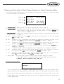
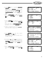
2) Name and Description of Each Display Contents on General Operation Mode
It is an initial screen when power is on for the first time, but display of screen can be changed according
to the general sewing related parameter.
POWER LED
READY LED
ERROR LED
NO:000
XS :1 0 0 %
YS :1 0 0 %
BC :0 0 0
NOR_SEW
SP:1500
PC:0000
A.“POWER LED”: When you turn on the power, this lamp also comes to light on.
B.“READY LED”: This lamp comes to light on when a machine is ready to work by reading patterns.
During reading or writing the patterns, the lamp flickers. If you press ENTER, you
can get out of the“READY”state.
C.“ERROR LED”: When errors including sensing thread and emergency stop happen this lamp comes
to light on.
D.“NO”: It indicates pattern No. Press NO key and input the pattern number you want by pressing
digit keys. (000 ∼ 999)
E.“XS”: It indicates a rate of enlargement and reduction for width. You can change the value at your
option by using digit keys after pressing down X SCALE key. (001[%] ∼400[%])
F.“YS”: It indicates a rate of enlargement and reduction for length. You can change the value at your
option by using digit keys after pressing down Y SCALE key. (001[%] ∼400[%])
G.“SP”: It indicates sewing speed. You can change the speed you want by pressing down SPEED key.
(200[SPM] ∼2500[SPM])
※ Maximum sewing speed varies depending on the sewing machine. See“Setting-Up the Speed”.
H.“BC”: It indicates setting value of bottom thread exchange counter. You can change the value at
your option by using digit key after pressing down B. SET key. (000 ∼ 999)
I. “PC” : It indicates setting value of working capacity. You can change the value at your option by
using digit keys after pressing down P. SET key. (0000 ∼9999)
J. “NOR_SEW”: It shows working condition. General sewing and chain sewing are available.
“ NOR_SEW”indicates the general sewing and“CHN_XX”means chain sewing.
※ Reference : 00~15 are available in XX of“CHN_XX”
※ In case of SPS/C-series :
Needle & Hook
Origin....
※ In case of SPS/C-series, when the power is on first, upper-lower shaft origin search motion will start. After
origin search motion, the highest position of thread take- up is set as the different way from the existing
pattern. Because origin search motion will perform to set upper-lower shaft hook time. This will not cause
problem during sewing or trimming. The position will be set as the existing pattern when the machine stops
or trims during sewing.
11
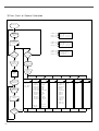
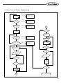
3) Flow Chart of General Operation
Power On
Indication of
general sewing
mode
POWER LED
General Sewing
mode
POWER LED
READY LED
ERROR LED
READY LED
ERROR LED
POWER LED
NO
NOR_SEW
SP:2000
PC:0000
<< Main Menu >>
0.Initialize
1.Parameter Set
2.Program
Selection of
working
mode
Read
USB flash
drive
0:Initialization
Light On for
preparation
1.
2.
3.
4.
Operation of
pedal switch
Sewing
12
SP:2000
PC:0000
Indication of
special working
mode
Selection of
pattern No.
NO
ERROR LED
NO:000
XS:100 %
YS:100 %
BC:000
NOR_SEW
YES
YES
Is ENTER
key pressed?
NO
Is MODE
key pressed?
Is NO key
pressed?
READY LED
NO:000
XS:100 %
YS:100 %
BC:000
YES
S/W Version
Para. Init.
Sys. UpDate
Para Ptrn
1:Parameter
setting
2:Pattern
programming
0. JOG En/Dis
1. JOG Mode
2. Machine Org1
3. Machine Org2
4. Strt Ret Mod
5. Bobbin Counter
6. Prodct Counter
7. Pattern Read
8. Trim EM Stop
9. Slow Start
10. Max Speed
11. Feed End Pos
12. FF Operation
.
.
0. TRIM
1. SEC_ORG
2. PAUSE
3. EMPTY
4. JUMP
5. POINT
6. LINE/CURVE
7. LINE
8. CURVE
9. ARC
10. CIRCLE
11. UMP SPD
12. STI SPD
.
.
◎ Refer the
appendix 3.
◎ Refer the
appendix 4.
3:Thread winding 4:Machine test
5:Pattern list
0. Encoder Test
0. Memory
1. XY Main Test 1. USB
2. MainMotor Test
3. Interrupt Test
4. PWM Test
5. LCD Test
6. Keyboard Test
7. Input0 Test
8. Input1 Test
9. Input2 Test
10. XY Jog Test
11. Solenoid Test
12. Origin Test
13. Jump Test
14. Asyne Test
(Direct Type)
6:Embroidery
data conversion
0. SWF
1. TAJIMA
7:JUKI Data
Conversion
JUKI(0)
4) Work Flow of Pattern Programming
General
sewing mode
NO
POWER LED
READY LED
ERROR LED
POWER LED
Is MODE key
pressed?
READY LED
ERROR LED
NO:000
XS:100 %
YS:100 %
BC:000
NOR_SEW
SP:2000
PC:0000
<< Main Menu >>
0.Initialize
1.Parameter Set
2.Program
YES
Selection of
working mode
POWER LED
READY LED
ERROR LED
<< Main Menu >>
2.Program
3.Bobbin Wind
4.Machine Test
A
NO
Pattern
Programming
Mode
Is TEST key
pressed?
YES
Light On for
preparation
Indication of
Programming
Mode
Is CODE key or
punching related
key pressed?
POWER LED
READY LED
ERROR LED
POWER LED
READY LED
ERROR LED
ORIGIN
X:00000A N:00000
Y:00000A
Function Code?
Operation of
pedal switch
<Function Code>
000:TRIM
001:SEC_ORG
002:PAUSE
Test Sewing
YES
Is TEST key
pressed?
Selection of
Programming Code
NO
YES
Is WRITE key
pressed?
Information Input of
Stitch Width and
Coordinates
NO
YES
Input of Pattern
No.
YES
Is ESC key
pressed?
NO
Is EXE key
pressed?
YES
Read
USB flash
drive
NO
NO
Is MODE key
pressed?
Pattern Data
Generation
A
End of Programming Mode
13
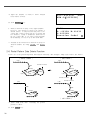
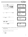
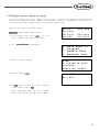
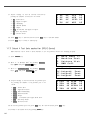
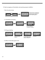
5) Operating After Reading the Patterns from USB flash drive
※ Caution : If READY LED turns on or upper feed plate is under, some keys are not available.
It happened, operate the keys after lifting the upper feed plate or pressing ENTER
A. Insert the USB flash drive stored sewing
patterns into the terminal.
B. After pressing NO key, input the pattern
number by using digit keys. (If you want to
work with“001”pattern, press [0][0][1])
C. Press ENTER key. Read the pattern and
change to sewing available mode.
D. At the moment, the upper thread plate comes
to descend, then ascend again after moving to
the sewing start point. The READY LED
comes to light on.
E. Press SPEED key and adjust the speed properly.
F. If you step on the pedal switch on the right
side, the upper feed plate comes to descend, and
if you step on the pedal switch on the left side,
the machine starts relevant work.
G. When you finish operating, the machine backs to
the origin or sewing start point, and the upper
feed plate comes to ascend.
NO :0 0 1
XS :1 0 0 %
YS:100%
BC :0 0 0
NO :0 0 1
XS :1 0 0 %
YS:100%
BC:000
key.
NOR_SEW
SP:2000
PC:0000
NOR_SEW
SP:1500
PC:0000
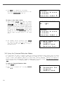
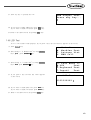
6) Confirming the Working Pattern Read from the USB flash drive
A. Insert a USB flash drive into the terminal.
B. After pressing NO key, input the pattern number
by using digit keys. (If you want to work with
“001”pattern, press [0][0][1])
C. Press ENTER key. Read the pattern and
change to sewing available mode.
D. At the moment, the upper thread plate comes
to descend, then ascend again after moving to
the sewing start point. The READY LED
comes to light on.
E. Press SPEED key and adjust the speed properly.
F. If you step on the pedal switch on the right
side, the upper feed plate comes to descend.
G. If you press FORW and BACK keys to progress
and reverse 1 stitch, you can confirm the real
shape to be sewn. If you press continuously, it
moves to the start or to the end of pattern
data consecutively.
H. If you want to finish working, press ORIGIN key.
I. If you want to continue sewing at the forward
or backward point, step on the left pedal switch.
J. When you finish operating, the machine backs to
the origin or sewing start point, and the upper
feed plate comes to ascend.
14
NO :0 0 1
XS :1 0 0 %
YS :1 0 0 %
BC :0 0 0
NOR_SEW
NO :0 0 1
XS :1 0 0 %
YS :1 0 0 %
BC :0 0 0
NOR_SEW
SP:2000
PC:0000
SP:1500
PC:0000
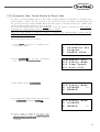
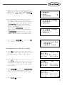
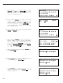
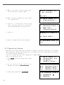
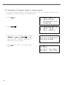
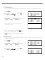
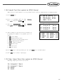
7) When a Machine Stops Operating During Sewing by the Thread Cut
A. You can get the screen like a figure on the right side.
B. If you want to sew continuously at the same
position, insert thread again, then step on the
left pedal switch. If you want to sew at the 1
stitch forward or backward point, after moving
by using FORW and BACK key and step on
the left pedal switch.
C. If you want to stop operation and restart
sewing from the beginning, press ORIGIN key.
The feed plate moves to the origin or sewing
start point and ascend.
D. When you finish operating, the machine backs to
the origin or sewing start point, and the upper
feed plate comes to ascend.
Err18
Thread Broken!
NO :0 0 1
XS :1 0 0 %
YS :1 0 0 %
BC :0 0 0
NOR_SEW
SP:2000
PC:0000
8) Emergency Stop During Operation
A. The machine stops operating immediately by
pressing EMERGENCY STOP switch during
sewing. Then you can get the screen like a figure
on the right side.
B. If you want to restart sewing from the beginning
after discontinuing it, Press the EMERGENCY
STOP switch once more to perform trimming.
(When manual trimming is set after emergency
stop) then press ORIGIN key. The feed plate
moves to origin then comes to ascend.
C. If you want to continue sewing, step on the left
pedal switch. If you finish every working, a
needle moves to origin and the upper feed plate
ascends.
Err17
Emergency Stop!
NO :0 0 1
XS :1 0 0 %
YS :1 0 0 %
BC :0 0 0
NOR_SEW
SP:2000
PC:0000
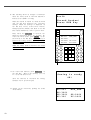
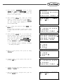
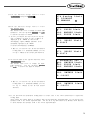
9) Winding the Thread
A. Inset the empty bobbin into a head of the
sewing machine.
B. Press MODE key.
C. Move to “3. Bobbin Wind” by using direction
keys
, then press ENTER key. At this
time, the upper feed plate comes to descend.
D. If you step on the left pedal switch, thread
winding starts to progress, and if you step on
the left pedal switch one more time, thread
winding comes to discontinue temporarily.
E. If you finish the thread winding work, complete
the thread winding with the left pedal switch
or ESC key.
<<
3.
4.
5.
Main Menu >>
Bobbin Wind
Machine Test
Pattern List
<<Bobbin Wind>>
15
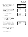
10) Safety Functions
10-1) Threading and Cancellation Key
When the sewing machine is in the ready position, press No. 5 key for threading (the presser foot and
the clamp descend). While threading, a user might mistakenly step on the operation pedal, and start the
operation, causing a safety problem. To prevent accidents, the function to freeze the operation after
threading was added.
However, the operation freeze status can be canceled by pressing the same No. 5 key again.
A. Sewing ready position
B. Press No. 5 key for threading. The following
message is displayed on the screen, and all keys
become disabled. The sewing operation pedal
switch is also disabled.
NO:001
XS:100%
YS:100%
BC:001
NOR_SEW
SP:1500
PC:0001
Threading...
To Release...
Press(5) again!
C. To cancel the freeze mode, press No. 5 key again.
D. When the safety mode is cancelled, the screen
returns to the original status.
16
NO:001
XS:100%
YS:100%
BC:001
NOR_SEW
SP:1500
PC:0001
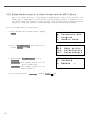
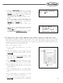
10-2) Emergency Stop, Thread Sensing or Pause Code.
In order to provide maximum safety to users, when a sewing machine is stopped due to emergency stop,
thread sensing or pause code, the operation of the pedal start switch, the clamp up/down switch and
the operation box keys become disabled. When the safety mode is cancelled, the keys are enabled again
and the sewing machine operation is back to normal.
To cancel the safety function, press the “EXE”key on the left bottom of the OP Box. When this key
is pressed, the sewing machine operation will go back to normal.
When the sewing machine is stopped in relation to emergency stop, thread sensing or pause code, the
clamp takes the down position.
The safety mode can be set as follows:
A. Press MODE and move to “Parameter Set”
on the Main Menu.
B. Press ENTER
to get into “Parameter
Set”. Move to“095. Safety Mode”.
<<
1.
2.
3.
Main Menu >>
Parameter Set
Program
Bobbin Wind
<Parameter Set>
095.Safety Mode
096.Jump Speed
097.Auto Call
C. The default value is 1) DISABLE.
095.Safety Mode
1) DISABLE
<2) ENABLE
D. To activate the safety mode, move the cursor
to 2) ENABLE and press ENTER .
095.Safety Mode
1) DISABLE
2) ENABLE
<-
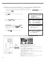
E. If the setting is completed, the safety mode
will be enabled in time of emergency stop,
thread sensing or pause code while sewing is
conducted.
17
F. The following shows an example of situations
where the safety mode is activated. Thread is
broken in the middle of sewing.
When the thread is sensed, an alarm is issued
and the OP Box displays the following
message. While the message is displayed on
the OP Box screen, Pedal Start Switch,
Clamp Up/Down Switch, and Keys of the OP
Box remain disabled in order to protect users.
Only when the exit key is entered, the
functions mentioned above are operable. To
cancel the safety mode, press “EXE” on the
left bottom of the OP Box. When this key is
pressed, the sewing machine operation will go
back to normal.
Err18
Thread Broken!
Press EXE Key
NO:123
XS:100%
YS:100%
BC:004
NOR_SEW
SP:1500
PC:9084
While the safety mode is effective, the clamp
is located down.
G. To cancel this function, press EXE Key on
the OP Box. This is the message you can
see on the OP Box screen.
After the function is cancelled, the sewing
machine can be operated again.
H. Sewing can be started by pressing the Pedal
Start Switch.
18
Sewing is ready
OK!
NO:003
XS:100%
YS:100%
BC:100
NOR_SEW
SP:2000
PC:0000
4
APPLICABLE OPERATION
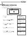
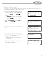
1) Pattern Data Generation Function
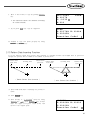
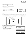
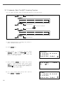
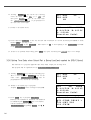
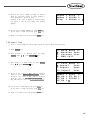
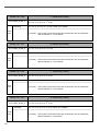
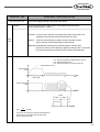
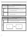
1-1) Program Example 1 : Generating the Square Pattern
→
→
(-650,300)
P1
(650,300)
P2
3mm
Move
JUMP
P4
(-650,-300)
A. Insert a USB flash drive into the terminal.
B. Press MODE key.
C. Move to “2. Program” by using direction keys
, then press ENTER key. At this time,
the upper feed plate comes to descend.
D. After pressing JUMP key, move to the initial
point of square by using direction keys. Then,
press PNT SET key.
E. If you press EXE key, the machine operates pattern
data, then the feed plate moves according to the
operated data.
F. After pressing LINE key, input the stitch width
by using the digit keys, then press ENTER
key. (For example, if you want to set the
stitch width as 3mm, input [0][3][0].)
(0,0)
P3
(650,-300)
<<
2.
3.
4.
Main Menu >>
Program
Bobbin Wind
Machine Test
ORIGIN
X:00000A N:00000
Y:00000A
Function Code?
004:JUMP
X:-0650
Y:00300
N:001
JUMP
NONE
X:-0650A N:00065
Y:00300A
Function Code?
007:LINE
WIDTH:030[0.1mm]
19
G. Move to each edge of the square by using
direction keys, then press PNT SET key to input
coordinates of each edge point. Whenever you
press the PNT SET key, the number on screen
will be increased.
H. If you press EXE key, the machine operates
pattern data, then the feed plate moves according
to the operated data.
I. Press TRIM key to input the trimming code.
Then, “000:TRIM”appears on the screen for a
little while, and you can see the screen like
a figure on the right side.
J. If you press FORW and BACK keys to progress
and reverse 1 stitch, you can confirm the real
shape to be sewn. Whenever you once press the
keys, you can see the operating form and
coordinates at that time. If you want to perform
test sewing, goes to the next step directly. If
you press continuously, it moves to the start or
to the end of pattern data consecutively.
K. Press TEST key.
The upper feed plate moves to origin and to the
sewing start point, then goes up again. READY
LED lights up. Press SPEED key and adjust
the speed properly. Then if you step on the
pedal switch on the right side, the upper feed
plate comes to descend, and if you step on the
pedal switch on the left side, the machine starts
test sewing. If the test sewing is finished, the
upper feed plate moves to the sewing start
point, then comes to ascend.
L. Press TEST key one more time and finish the
test sewing. Then, the upper feed plate comes to
descend and moves to origin with the turning
off the READY LED.
M. Press WRITE key and input the number you
want to save by using digit keys, then press
ENTER key. (For example, if you want to
save a pattern number as 300, input [3][0][0].)
It you do that, the generated pattern data will
be saved in a floppy disk to that number.
During saving the pattern, the READY LED
flickers.
20
007:LINE
X:-0650
Y:00300
N:004
LINE
NONE
X:-0650A N:00193
Y:00300A
Function Code?
TRIM
NONE
X:-0650A N:00194
Y:00300A
Function Code?
LINE
NONE
X:-0650A N:00193
Y:00300A
Function Code?
<Test Sewing>
SP:1200
ORIGIN
X:00000A N:00000
Y:00000A
Function Code?
015:PTRN WRITE
NO
:300
N. If there already exists the pattern number that
you want to save in a USB flash drive, you can
see the screen like a figure on the right side. If
you want to save the pattern with the same
number, just press ENTER
key, but if you
want to save it with another number, press ESC
key and save to the other number.
Pattern Exist!
OverWrite?
Y(ENTER)/N(ESC)
O. For finishing a pattern generation, press MODE
key. Then, the upper feed plate moves to the
origin and comes to ascend. Press ESC key to
back to the initial screen.
ORIGIN
X:00000A N:00000
Y:00000A
Function Code?
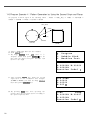
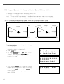
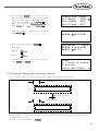
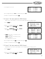
1-2) Program Example 2 : Generating the Circle Pattern
To generate circle patterns, input 3 random coordinates that pass on the circle.
P1(0,300)
↔
(0,0)
3mm
JUMP
P2(300,0)
P1(0,-300)
A. Insert a USB flash drive into the terminal.
B. Press MODE key.
C. Move to “2. Program” by using direction keys
, then press ENTER key. At this time,
the upper feed plate comes to descend.
<<
2.
3.
4.
Main Menu >>
Program
Bobbin Wind
Machine Test
ORIGIN
X:00000A N:00000
Y:00000A
Function Code?
D. After pressing JUMP key, move to a random
coordinates (For example, X:00000, Y:00300)
that passes on circle by using direction keys.
Then, press PNT SET key.
004:JUMP
X:00000
Y:00300
N:001
21
E. If you press EXE key, the machine operates
pattern data, then the feed plate moves according
to the operated data.
F. After pressing CODE key, if you know function
codes related to pattern programming, input three
digit number, but if not, move to “10. Circle”
by using direction keys
after pressing
ENTER key, then press ENTER key again.
G. Input the stitch width by using the digit keys,
then press ENTER key. (For example, if you
want to set the stitch width as 3mm, input
[0][3][0].)
H. Move to the second random coordinates that
passes on a circle (For example, X:00300
Y:00000) by using direction keys, then press PNT
SET key. Same as above, move to the third
random coordinates that passes on a circle (For
example, X:00000 Y:-00300), then press PNT
SET key. Whenever you press PNT SET key,
the number of screen increases.
I. If you press EXE key, the machine operates
pattern data, then the feed plate moves according
to the operated data.
J. Press TRIM key to input the trimming code.
Then, “000:TRIM”appears on the screen for a
little while, and replace the screen like a
figure on the right side.
K. If you press FORW and BACK keys to progress
and reverse 1 stitch, you can confirm the real
shape to be sewn. Whenever you once press the
keys, you can see the operating form and
coordinates at that time. If you want to perform
test sewing, goes to the next step directly. If you
press continuously, it moves to the start or to
the end of pattern data consecutively.
L. Press TEST key.
The upper feed plate comes to ascend and
moves to the origin or sewing start point, then
goes up. After that, READY LED turns on.
Press SPEED key and adjust the speed properly.
Then if you step on the pedal switch on the
right side, the upper feed plate comes to descend,
and if you step on the pedal switch on the left
side, the machine starts test sewing. If the test
sewing is finished, the upper feed plate moves to
origin and comes to ascend.
22
JUMP
NONE
X:00000A N:00027
Y:00300A
Function Code?
<Function Code>
010:CIRCLE
<
011:JUMP
SPD
012:STI
SPD
010:CIRCLE
WIDTH:030[0.1mm]
010:CIRCLE
X:00000
Y:-0300
N:002
CIRCLE
NONE
X:00000A N:00090
Y:00300A
Function Code?
TRIM
NONE
X:00000A N:00091
Y:00300A
Function Code?
CIRCLE
NONE
X:00000A N:00090
Y:00300A
Function Code?
<Test Sewing>
SP:1500
M. Press TEST key one more time and finish the
test sewing. Then, the upper feed plate comes to
descend and move to origin with the turning off
the READY LED.
ORIGIN
X:00000A N:00000
Y:00000A
Function Code?
N. Press WRITE key and input the number you
want to save by using digit keys, then press
ENTER key. Then, save the generated pattern
data in a USB flash drive as a relevant number.
(For example, if you want to save a pattern
number as 301, input [3][0][1].)
During saving the data, READY LED flickers.
If you want to save the pattern with the same
number, just press ENTER key, but if you
want to save it with another number, press ESC
key and save to the other number. After
finishing saving process, the upper feed plate
backs to the origin.
015:PTRN WRITE
NO
:301
ORIGIN
X:00000A N:00000
Y:00000A
Function Code?
O. For finishing a pattern generation, press MODE
key. Then, the upper feed plate moves to the
origin and comes to ascend. Press ESC key to
back to the initial screen.
<<
2.
3.
4.
Main Menu >>
Program
Bobbin Wind
Machine Test
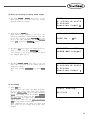
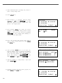
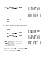
1-3) Program Example 3 : Generating the Double Curve Pattern
Input a curving spot that inclines largely among spots that pass on a curve. We give 5 curving lines for
examples here.
(-300,200)
(-600,0)
(0,0)
(600,0)
(300,-200)
A. Insert a USB flash drive into the terminal.
B. Press MODE key.
<<
2.
3.
4.
Main Menu >>
Program
Bobbin Wind
Machine Test
23
C. Move to“2. Program”by using digit keys
,
then press ENTER key. At this time, the
upper feed plate comes to descend and moves to
the origin.
D. After pressing JUMP key, move to a random
coordinates (For example X:-0600, Y:00000)
that passes on a circle by using direction keys.
Then, press PNT SET key.
E. If you press EXE key, the machine operates
pattern data, then the feed plate moves according
to the operated data.
F. After pressing CODE key, If you know function
codes related to pattern programming, input
three digit number, but if not, move to “28.
Curve DBL”by using direction keys
, after
pressing ENTER key, then press ENTER
key again.
G. Input the stitch width by using the digit keys,
then press ENTER
key. (For example, if you
want to set the stitch width as 3mm, input
[0][3][0].) Input the distance between the two
curves by using digit keys, then press ENTER
key. (For example, if you want to set 5mm,
input [0][5][0].) Input a direction from
standard curve by using digit keys, then press
ENTER key. (For example, if you want to
place another curve on above the standard
curve, input [0].)
H. Move to the next coordinates (For example, X:0300 Y:00200) by using direction keys, then press
PNT SET key. Same as above, move to the
other three coordinates in turns by using direction
keys and press PNT SET key. At this time,
whenever you press PNT SET key, the number
of screen increases.
I. If you press EXE key, the machine operates
pattern data, then the feed plate moves
according to the operated data. At this time, the
sewing machine discontinues for a while.
24
ORIGIN
X:00000A N:00000
Y:00000A
Function Code?
004:JUMP
X:-0600
Y:00000
N:001
JUMP
NONE
X:-0600A N:00054
Y:00000A
Function Code?
<Function Code>
028:CURVE
DBL <
029:ARC
DBL
030:CIRCLE DBL
028:CURVE DBL
WIDTH:030[0.1mm]
OFSET:050[0.1mm]
DIR:0[0/1]
028:CURVE DBL
X:00600
Y:00000
N:004
CURVE
DBL
NONE
X:-0635A N:00157
Y:00035A
Function Code?
J. Press TRIM key to input the trimming code.
Then, “000:TRIM”appears on the screen for a
little while, and you can see the screen like
a figure on the right side.
K. If you press FORW and BACK keys to progress
and reverse 1 stitch, you can confirm the real
shape to be sewn. Whenever you once press the
keys, you can see the operating form and
coordinates at that time. If you want to perform
test sewing, goes to the next step directly. If
you press continuously, it moves to the start or
to the end of pattern data consecutively.
L. Press TEST key.
The upper feed plate comes to ascend and moves
to origin, then goes up. After that, READY
LED lights up. Press SPEED key and adjust
the speed properly. Then if you step on the
pedal switch on the right side, the upper feed
plate comes to descend, and if you step on the
pedal switch on the left side, the machine starts
test sewing. If the test sewing is finished, the
upper feed plate moves to origin or sewing start
point and comes to ascend.
M. Press TEST key one more time and finish the
test sewing. Then, the upper feed plate comes to
descend and moves to origin with the turning on
the READY LED.
N. Press WRITE key and input the number you
want to save by using digit keys, then press
ENTER key. Then, save the generated
pattern data in a USB flash drive as a relevant
number.(For example, if you want to save a
pattern number as 302, input [3][0][2].)
During saving the data, READY LED flickers.
If you want to save the pattern with the same
number, just press ENTER key, but if you
want to save it with another number, press
ESC key and save to the other number. After
finishing saving process, the upper feed plate
backs to the origin.
O. For finishing a pattern generation, press MODE
key. Then, the upper feed plate comes to ascend
after moving to origin. Press ESC key to
back to the initial screen.
TRIM
NONE
X:-0635A N:00158
Y:00035A
Function Code?
CURVE
DBL
NONE
X:00600A N:00103
Y:00000A
Function Code?
<Test Sewing>
SP:1500
ORIGIN
X:00000A N:00000
Y:00000A
Function Code?
015:PTRN WRITE
NO
:302
ORIGIN
X:00000A N:00000
Y:00000A
Function Code?
<<
2.
3.
4.
Main Menu >>
Program
Bobbin Wind
Machine Test
25
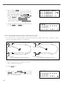
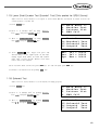
1-4) Program Example 4 : Pattern Generation by Using the Second Origin and Pause
To program as below, input as the following orders : JUMP → SEC_Org → JUMP → CIRCLE →
TRIM → PAUSE → JUMP → LINE → TRIM
(SEC_ORG)
(JUMP)
P2
P3
P1
P4
P7
P5
P6
(0,0)
(PAUSE)
(CIRCLE)
A. Insert a USB flash drive into the terminal.
B. Press MODE key.
C. By using direction keys
, move to “2.
Program” menu, then press ENTER key. At
this time the upper feed plate descends, and
moves to the origin.
(LINE)
<<
2.
3.
4.
Main Menu >>
Program
Bobbin Wind
Machine Test
ORIGIN
X:00000A N:00000
Y:00000A
Function Code?
D. After pressing JUMP key, make the second
origin move to the coordinates (For example,
X:00000 Y:00300) you want by using direction
keys, then press PNT SET key.
E. By pressing EXE key, after operating the
pattern data, the feed plate moves according to
the operated pattern data.
26
004:JUMP
X:00000
Y:00300
N:001
JUMP
NONE
X:00000A N:00027
Y:00300A
Function Code?
F. After pressing CODE key, input the three digit
numbers if you know the pattern programming
related function code, but if you don’t know it,
press ENTER key and move to “001: SEC_
ORG”by using direction keys
, then press
ENTER key again.
G. After pressing JUMP key, move to one random
coordinates that passes through circle (for
example, X:-0100, Y:00000), then press PNT
SET key.
H. By pressing EXE key, the feed plate moves
according to the operated data after operating
the pattern data.
<Function Code>
001:SEC_ORG
<
002:PAUSE
003:EMPTY
004:JUMP
X:-0100
Y:00000
N:001
JUMP
NONE
X:-0100A N:00056
Y:00000A
Function Code?
I. After pressing CODE key, input the three digit
numbers if you know the pattern programming
related function code, but if you don’t know it,
press ENTER key and move to “010: Circle”
by using direction keys
, then press ENTER
key again.
<Function Code>
010:CIRCLE
<
011:JUMP
SPD
012:STI
SPD
J. By using digit keys, input the stitch width and
press ENTER key.
(For example, if you set up the stitch width as
3mm, input [0][3][0].)
010:CIRCLE
WIDTH:030[0.1mm]
K. By using direction keys, move to the second
random coordinates that passes through circle
(for example, X:-0300 Y:00200), then press
PNT SET key.
Likewise move to the third coordinates that
passes through circle (for example, X:-0500
Y:00000), then press PNT SET key.
At this time the number on screen increases
whenever you press PNT SET key.
010:CIRCLE
X:-0500
Y:00000
N:002
27
L. By pressing EXE key, the feed plate moves
according to the operated data after operating
the pattern data.
M. By pressing TRIM key, input the code for trim.
Then, after appearing “00:TRIM”on the screen
for a moment, then a screen of the right side
appears.
N. After pressing CODE key, input the three digit
numbers if you know the pattern programming
related function code, but if you don’t know it,
press ENTER key and move to“002: PAUSE”
by using direction keys
, then press ENTER
key.
O. After pressing JUMP key, move to the one
random coordinates of straight line (for example,
X:00100 Y:00200)by using direction keys, then
press PNT SET key.
28
CIRCLE
NONE
X:-0100A N:00098
Y:00000A
Function Code?
TRIM
NONE
X:-0100A N:00099
Y:00000A
Function Code?
<Function Code>
002:PAUSE
<
003:EMPTY
004:JUMP
004:JUMP
X:00100
Y:00200
N:001
P. By pressing EXE key, the feed plate moves
according to the operated data after operating
the pattern data.
JUMP
NONE
X:00100A N:00125
Y:00200A
Function Code?
Q. After pressing CODE key.
If you know the function number related to
pattern programming, input three-figure number
and if you do not know the number, press
ENTER key and transfer to“007:Line”menu
by using direction key
, and then press
ENTER key.
Ref.)“LINE”and“CURVE”function is set to
use with hot key on the operation
panel and so you may press this key.
<Function Code>
007:LINE
<
008:CURVE
009:ARC
R. By using the digit keys, input the stitch width
and press ENTER key.
(For example, if you set up the stitch width as
3mm, input [0][3][0].)
S. By using direction key, move to the another
coordinates in turns that passes through line,
then press PNT SET key.
At this time the number on screen increases
whenever you press PNT SET key.
T. By pressing EXE key, the feed plate moves
according to the operated data after operating
the pattern data.
U. By pressing TRIM key, input the code for trim.
Then, after appearing “00:TRIM”on the screen
for a moment, then a screen of the right side
appears.
V. After pressing WRITE key, input the number
you want to save by using digit keys. then
press ENTER key. Save the generated pattern
data in a USB flash drive as a relevant number.
(For example, if you want to save the pattern
number as 303, input [3][0][3].) During saving
the pattern, the READY LED flickers. When a
pattern of same number is in a USB flash drive
and if you want to save another pattern as
same number, press ENTER key. If you want
to save the pattern as another number, press
ESC key and save it as another number. After
finishing saving, the upper feed plate moves to
the origin again.
W. For finishing pattern generation, press MODE
key. Then the upper feed plate moves to the
origin and ascends. Press ESC key to back to
the initial screen.
007:LINE
WIDETH:030[0.1mm]
007:LINE
X:00100
Y:00200
N:004
LINE
NONE
X:00100A N:00181
Y:00200A
Function Code?
TRIM
NONE
X:00100A N:00182
Y:00200A
Function Code?
015:PTRN WRITE
NO
:303
ORIGIN
X:00000A N:00000
Y:00000A
Function Code?
<<
2.
3.
4.
Main Menu >>
Program
Bobbin Wind
Machine Test
29
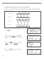
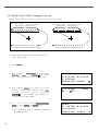
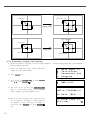
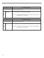
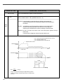
1-5) ZigZag Shape Selecting Function to Generate ZigZag
It was made to select 4 kinds of “DIR” values from existing 0/1 to 0/1/2/3 among three parameters
inputting to create Line ZigZag, Curve ZigZag, Arc ZigZag, Circle ZigZag and accordingly ZigZag shapes
are classified into 4 type.
For DIR=0
For DIR=1
For DIR=2
For DIR=3
A. Insert a USB flash drive into the terminal.
B. Press MODE key.
30
<<
2.
3.
4.
Main Menu >>
Program <
Bobbin Wind
Machine Test
C. Move to“2. Program”menu by using direction key
and press ENTER key. Then, the upper
feed plate comes down and moves the original
point.
ORIGIN
X:00000A N:00000
Y:00000A
Function Code?
D. After pressing JUMP key, move to the coordinate
(for example:X:-0650 Y:00000) to locate by using
direction key. Then, press PNT SET key.
JUMP
X:-0650A
Y:00000A
N:001
E. If you press EXE key, after calculation on
pattern data, feed plate moves according to the
calculated data.
JUMP
NONE
X:-0650A N:00000
Y:00000A
Function Code?
F. After pressing CODE key, if you know the
function number related to pattern programming,
input three figure digit number and if you do
not know the number, press ENTER key. Then
after moving to “019: LINE ZIG” menu by
using direction key, press ENTER key.
<Function
019:LINE
020:CURVE
021:ARC
G. Input ZigZag width by using digit key, press
ENTER key and input ZigZag stitch width.
Then, press ENTER key and input DIR value
by using digit key to select ZigZag shape to
create. And press ENTER key.
010:LINE
ZIG
WIDTH:030[0.1mm]
PITCH:030[0.1mm]
DIR:3[0->3]
H. Move ZigZag line (Ex: X: 00650 Y: 00000) to
the last sewing coordinate by using direction key
again and press PNT SET key.
017:LINE
X:00650
Y:00000
N:001
I. If you press EXE key, after calculation on
pattern data, feed plate moves according to the
calculated data.
LINE
ZIG
NONE
X:00650A N:00000
Y:00000A
Function Code?
J. Input thread trimmer key by pressing TRIM
key. Then “00:TRIM” screen appears for a
second and then the screen like the figure in the
right side appears again.
TRIM
NONE
X:00650A N:00000
Y:00000A
Function Code?
K. You can confirm the shape to be actually sewed
by pressing FORW key and BACK key. Every
time you press once, it moves by one stitch and
show work mode and coordinate at the moment.
When you want to actually do initial sewing,
skip to next. If you press continuously, it moves
to the start or to the end of pattern data
consecutively.
LINE
ZIG
NONE
X:00650A N:00000
Y:00000A
Function Code?
L. Press TEST key. The upper feed plate moves to the
original point or sewing start point and goes up
and READY LED is turned on. After adjusting
appropriate initial sewing speed by pressing SPEED
key, step on the pedal switch in the right. Then, the
upper feed plate comes down and stepping on the left
pedal, it performs initial sewing. The upper feed plate
that completed initial sewing moves to the original
point or sewing start point and then goes up.
<Test Sewing>
Code>
ZIG
<
ZIG
ZIG
ZIG
SP:1500
M. The order of saving and completion is the same
as the previous example.
31
2) Pattern Data Edit Function
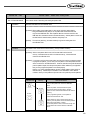
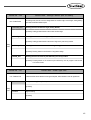
2-1) One Stitch Movement Function
It uses when correcting the location of one stitch in the formed sewing shape.
Existing Location
Location Movement
New Location
< Before Location Change >
A. Insert USB flash drive containing the pattern to
change movement of a stitch.
B. Press MODE key.
32
< After Location Change >
<<
2.
3.
4.
Main Menu >>
Program <
Bobbin Wind
Machine Test
C. After moving to “2. Program” menu by using
direction key
, press ENTER key. At this
time, the upper feed plate comes down and
move the original point.
ORIGIN
X:00000A N:00000
Y:00000A
Function Code?
D. After pressing READ key, input the pattern
number to change movement of a stitch by
moving the digit key and read in the pattern by
pressing ENTER key. (For example, to read
pattern number 001, input [0][0][1]).
014:PTRN
NO
:001
E. Go to the location of stitch to correct by using
FORW and BACK key.
LINE
X:-0001A N:00059
Y:00000A
Function Code?
F. After pressing CODE key, if you know the
function number 051 related to pattern
programming, input three figure of digit number
and if you do not know the number, press
ENTER key and move to “051:STITCH
DRAG”by using direction key
. Then, press
ENTER key.
<Function Code>
051:STITCH DRAG<
052:STITCH DEL
053:MOV SEWSTAR
READ
G. Move to the location desired movement of one
stitch by using direction key.
※ X-Y coordinate value is different according
to location of needle.
051:STITCH
X:-00001
Y:-00060
N:000
DRAG
H. If you press EXE key, change to new needle
location is completed.
I. Confirm if needle location was changed to the
desired location by using FORW and BACK
key.
LINE
X:-0001A N:00059
Y:-0060A
Function Code?
2-2) Partial Movement Function of Pattern Data
Move part of pattern to different location among the sewing shape.
Start Point of Movement Scope
End Point of Movement Scope
Location to Move
Scope to Move
< Before Movement >
< After Movement >
A. Insert partial pattern data into the USB flash
drive containing the pattern to move and
change.
B. Press MODE key.
C. After moving to “2. Program” menu by using
direction key
, press ENTER key. At this
time, the upper feed plate comes down and
moves to the original point.
<<
2.
3.
4.
Main Menu >>
Program <
Bobbin Wind
Machine Test
ORIGIN
X:00000A N:00000
Y:00000A
Function Code?
33
D. After pressing READ key, input the pattern
number to move and change partial pattern
data by using digit key and read in the pattern
by pressing ENTER key. (For example, input
[0][0][1] to read the pattern number 001.)
014:PTRN
NO
:001
E. Go to the needle location to partially move by
using FORW and BACK key.
JUMP
X:00174A N:00070
Y:00183A
Function Code?
Reference) Location of the needle for partial movement
should be placed at the first start needle location that
actually sews. Therefore, if the sewing data that has
line property after jump appears, the last location of
JUMP data is the first start location of needle correction.
READ
F. After pressing CODE key, if you know the
function number related to pattern programming,
input three figure digit number 046, but if you
do not know the number, press ENTER key.
Then after move to “046:MOV PTRN” by
using direction key
, press ENTER key.
<Function Code>
046:MOV
PTRN<
052:COPY
PTRN
053:DEL
PTRN
G. Go to the last location of pattern to move by
using FORW key.
<RANGE SETTING>
X:00174A N:00088
Y:00183A
※ The indicated values are different according
to current location.
H. If you press EXE key, it becomes the state
that the selected pattern for partial movement
can move to the optional location.
046:MOV
X:00174
Y:00183
N:000
PTRN
I. Move to the location to move by pressing direction
key.
046:MOV
X:00174
Y:-0101
N:000
PTRN
J. If you press EXE key, movement is completed.
LINE
X:00174A N:00096
Y:-00101A
Function Code?
K. Confirm if movement was properly made by
using FORW and BACK key.
34
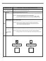
2-3) A Fixed Number of Stitch Delete Function
Delete 1-99 stitch in the pattern data shape after the start point to delete at present.
Delete Start Point
Delete Start Point
JUMP
Number of Stitch to delete
< Before Delete >
Number of deleted Stitch
< After Delete >
A. Insert USB flash drive containing the pattern to
delete stitches.
B. Press MODE key.
C. After moving to “2. Program” menu by using
direction key
, press ENTER key. At this
time, the upper feed plate comes down and
moves to the original point.
ORIGIN
X:00000A N:00000
Y:00000A
Function Code?
D. After pressing READ key, input the pattern
number to delete stitch by using the digit key
and read in the pattern by pressing ENTER
key. (For example, input [0][0][1] to read the
pattern 001.)
014:PTRN
NO
:001
E. Go to needle location to delete by using FORW
and BACK key.
LINE
X:-0025A N:00059
Y:00000A
Function Code?
※ X-Y coordinate value is different according to
needle location.
F. After pressing CODE key, if you know the
function number 052 related to pattern
programming, input three-figure digit number
and if you do not know, press ENTER key.
Then after moving to “052:STITCH_DEL”by
using direction key
, press ENTER key.
READ
<Function Code>
052:STITCH_DEL <
053:MOV SEWSTRT
054:MOV 2ndORG
35
G. Input the number of stitch to delete behind
from current location.
H. Press ENTER
052:STITCH
DEL
NUM:10[STITCH]
key.
I. Stitch is deleted as many as the input number.
Reference) After deleting as much as the number of
defined stitches, if end point and start point of two
sewing data existing at both sides do not match and
have distances, a jump is automatically made between
the two sewing data. If you want to input automatic
thread trimming, you can set up at“057:AUTO TRM”.
TRIM
X:-0233A N:00033
Y:00120A
Function Code?
J. Confirm if the stitches were deleted as many as
desired number by using FORW and BACK
key.
2-4) Partial Pattern Data Delete Function
Delete one of the generated pattern data shapes selectively (For example: Jump, Line, Curve, Arc, Circle).
< CIRCLE Delete >
< LINE Delete >
LINE
LINE
Needle Position
ARC
ARC
CURVE
LINE
LINE
CURVE
CIRCLE
LINE
LINE
LINE
LINE
Needle Position
LINE
LINE
JUMP
Needle Position
ARC
CURVE
LINE
LINE
CURVE
LINE
< ARC Delete >
A. Insert USB flash drive containing the partial
pattern to delete.
B. Press MODE key.
36
LINE
C. After moving to “2. Program” menu by using
direction key
press ENTER key. At this
time, the upper feed plate comes down and
moves to the original point.
ORIGIN
X:00000A N:00000
Y:00000A
Function Code?
D. After pressing READ key, input the pattern
number to delete partial pattern by using digit
key and read in the pattern by pressing
ENTER key. (For example, input [0][0][1] to
read the pattern number 001).
014:PTRN
NO
:001
E. Go to the pattern that the shape to delete
exists by using FORW and BACK key.
CIRCLE
X:-0067A N:00052
Y:-0092A
Function Code?
※ X-Y coordinate value is different according
to needle location.
READ
F. Delete is available by two methods as below.
- After pressing CODE key, input Function code
039 and press ENTER key.
- Or press PTN. DEL key of OP.
G. Press PTN.DEL key on operation box (OP).
Reference) After deleting as much as the number of
defined stitches, if end point and start point of two
sewing data existing at both sides do not match and
have distances, a jump is automatically made between
the two sewing data. If you want to input automatic
thread trimming, you can set up at“057:AUTO TRM”.
TRIM
X:-0220A N:00029
Y:00040A
Function Code?
H. Confirm if desired partial pattern shape was
deleted by using FORW and BACK key. (Line
is deleted by once.)
I. Delete the partial pattern data to delete
repeatedly in the order of E-F-G.
37
2-5) Partial Stitch Width Changing Function
Change stitch width by selecting a fixed part from the pattern shape.
Start Point of Stitch
Width Change
End Point of Stitch
Width Change
Current Stitch Width 3.0mm
< Before Partial Stitch Width Change >
Start Point of Stitch
width Change
End Point of Stitch
Width Change
Current Stitch Width 2.0mm
< After Partial Stitch Width Change >
A. Insert USB flash drive containing the pattern to
change stitch width.
B. Press MODE key.
C. After moving to “2. Program” menu by using
direction key
, press ENTER key. At this
time, the upper feed plate comes to descend.
ORIGIN
X:00000A N:00000
Y:00000A
Function Code?
D. After pressing READ key, input the pattern
number to change stitch width by using digit
key and read in the pattern by pressing
ENTER key. (For example, input [0][0][1] to
read the pattern number 001.)
014:PTRN
NO
:001
E. Go to the location to start change of stitch
width by using FORW and BACK key.
LINE
X:-0070A N:00021
Y:00140A
Function Code?
※ X-Y coordinate value is different according
to needle location.
38
READ
F. After pressing CODE key, if you know the
function number related to pattern programming,
input three-figure digit number 013, and if you
do not know, press ENTER key. Then after
moving to“013:STI WIDT”by using direction key
, press ENTER key.
<Function Code>
013:STI
WIDT<
014:PTRN
READ
015:PTRN
WRITE
G. Input the stitch width value to change and
press ENTER key.
013:STI
READ
WIDTH:020[0.1mm]
H. Move to the location to complete stitch width
change by using FORW and BACK key.
<RANGE SETTING>
X:00142A N:00029
Y:00089A
I. If you press EXE key, change of stitch width is
completed.
ARC
X:00133A N:00052
Y:00061A
Function Code?
※ X-Y coordinate values are
according to current location.
different
J. Confirm if change of stitch width was made
properly by using FORW and BACK key.
2-6) Pattern Partial Copy Function
Set a fixed part of pattern shape and copy to desired location.
Copy Start Point
Copy End Point
Location to Copy
Scope to Copy
39
A. Insert USB flash drive containing partial pattern
to make partial copy.
B. Press MODE key.
C. After moving to “2. Program” menu by using
direction key
, press ENTER key. At this
time, the upper feed plate comes down and
moves to the original point.
ORIGIN
X:00000A N:00000
Y:00000A
Function Code?
D. After pressing READ key, input the pattern
number to copy partial pattern by using digit
key and read in the pattern by pressing
ENTER key. (For example, input [0][0][1] to
read the pattern number 001.)
014:PTRN
NO
:001
E. Go to copy start location by using FORW and
BACK key.
JUMP
X:00174A N:00070
Y:00183A
Function Code?
Reference) Location of the needle for partial copy should be
placed at the first start needle location that actually sews.
Therefore, if the sewing data that has line property next
jump appears, the last location of JUMP data is the first
start location of needle correction.
F. After pressing CODE key, if you know the
function number related to pattern programming,
input three-figure digit number 047, and if you
do not know the number, press ENTER ey.
Then, after moving to “047:COPY PTRN” by
using direction key
, press ENTER key.
<Function Code>
047:COPY
PTRN<
048:DEL
PTRN
049:REV
SET
G. Go to the copy completing location of pattern
by using FORW key.
<RANGE SETTING>
X:00174A N:00088
Y:00183A
※ X-Y coordinate values are
according to current location.
different
H. If you press EXE key, it becomes the state to
move to the location to copy.
40
READ
047:COPY
X:00174
Y:00183
N:000
PTRN
I. Move to the location to copy by pressing direction
key.
※ The indicated values are different according
to current location.
J. If you press EXE key, copy is completed.
047:COPY
X:00174
Y:-0133
N:000
PTRN
LINE
X:00174A N:00088
Y:00183A
Function Code?
K. Confirm if copy was made properly by using
FORW and BACK key.
2-7) Pattern Data Inserting Function
It is the function made that pattern data inserting is available because the behind data is protected
though new pattern data is added in the middle of pattern data.
Pattern Data
Start Point
Inserting Point
Pattern Data Pattern Data
End Point
Start Point
< Before Pattern Data Insertion >
Inserting Point
Pattern Data
End Point
< After Pattern Data Insertion >
A. Insert USB flash drive containing the pattern to
insert.
B. Press MODE key.
C. After moving to “2. Program” menu by using
direction key
, press ENTER key. At this
time, the upper feed plate comes down and
moves to the original point.
ORIGIN
X:00000A N:00000
Y:00000A
Function Code?
41
D. After pressing READ key, input the pattern
number to insert pattern by using digit key and
read in the pattern by pressing ENTER key.
(For example, input [0][0][1] to read the
pattern number 001.)
014:PTRN
NO
:001
E. Go to the location of data to insert by using
FORW and BACK key.
LINE
X:-0012A N:00032
Y:00000A
Function Code?
F. Select LINE of operation box (OP) of the
function code to insert. After pressing CODE
key, if you know the function number related to
pattern programming, input three-figure digit
number and if you do not know the number,
press ENTER key. Then after selecting the
function number by using direction key
,
press ENTER key.
<Function Code>
047:LINE
<
048:CURVE
049:CIRCLE
G. Input stitch width and press ENTER
007:LINE
WIDTH:020[01.mm]
key.
H. Insert data of the shape to insert by using
direction key. (Same as sewing data generation by
using LINE)
007:LINE
X:-0203
Y:-0207
N:001
I. If you input data of the shape to insert each,
press EXE key.
LINE
X:-0209A N:00071
Y:00000A
Function Code?
J. Confirm if new pattern data was inserted
properly by using FORW and BACK key.
42
READ
3) Pattern Data Application Function
3-1) Operation after reading pattern data from USB flash drive and moving the second temporary start point
It is possible to move to the sewing start point or the second origin by using direction keys in the sewing
available state. To decide the moving point, whether it is the sewing start point or the second origin, set
up 1) PNT_STR_POS or 2) SECND_ORG at the general sewing related parameter No.“001. Move to
starting point/the second origin manually.”
※ Note : It is available when READY LED turns on, and this function is used for movement to the
temporary sewing start point or the second origin. By setting up the second origin within
pattern data, the same position can be set up as the second origin.
(650,300)
Y
(0,0)
X
(-650,-300)
A. Insert a USB flash drive into the terminal.
B. Press NO key, then input the pattern number
by using digit keys. (If you want to work with
“001”pattern, input [0][0][1].)
C. Press ENTER key to read a pattern and to
change to sewing available mode.
D. The upper feed plate comes to descend and
moves to the origin or sewing start point then
ascends. READY LED lights up.
E. Press SPEED key to adjust speed properly.
F. If you step on the pedal switch on the right side,
the upper feed plate comes to descend.
G. After moving to a random second origin by
using direction keys, if you step on the pedal
switch on the left side, the machine moves to
the sewing start point or the second origin and
starts relevant works. At this time, be careful
not to exceed the transfer limit of feed plate.
H. If the work is finished, a needle moves to the
origin or the sewing start point and the upper
feed plate comes to ascend. If you want to
back to the initial sewing start point or the first
origin, press ENTER key to read the pattern
to work one more time.
NO :0 0 1
XS :1 0 0 %
YS :1 0 0 %
BC :0 0 0
NOR_SEW
NO :0 0 1
XS :1 0 0 %
YS :1 0 0 %
BC :0 0 0
NOR_SEW
SP:2000
PC:0000
SP:1500
PC:0000
43
3-2) Program Example 5 : Change of Sewing Speed Within a Pattern
There are two ways to change sewing speed within a pattern.
1) Changing the sewing speed from an existing pattern data
2) Changing the sewing speed with creating new pattern data
※ Ref. : Several sections of speed change is available, but they should be within real sewing range.
Maximum speed varies depending on the pattern of the sewing machine.
3-2-1) Changing the Sewing Speed from an Existing Pattern Data
P1
P2
2000spm
Line
P1
2000spm
R1
(JUMP)
2000spm
P4
500spm
Line
2000spm P2
R2
(JUMP)
(0,0)
2000spm
2000spm
2000spm
P3
P4
(0,0)
2000spm
P3
2000spm
(1) Reading the Pattern that is Supposed to Change
the Sewing Speed
A. Insert the USB flash drive of a pattern that is
supposed to change the sewing speed.
B. Press MODE key.
C. By using direction keys
, move to “2.
Program”menu, then press ENTER key.
At this time the upper feed plate descends, and
moves to the origin.
D. After pressing READ key, input the pattern
number that is supposed to change the sewing
speed by using digit keys, then press ENTER to
read the pattern.
(For example, to read the pattern number 500,
input [5][0][0].)
44
<<
2.
3.
4.
Main Menu >>
Program
Bobbin Wind
Machine Test
ORIGIN
X:00000A N:00000
Y:00000A
Function Code?
014:PTRN
NO
:500
READ
(2) Setting up the Range of Sewing Speed Change
A. By using FORW, BACK keys, move to the
start point (R1) of section that the sewing
speed is supposed to change.
LINE
X:-0350A N:00075
Y:00300A
Function Code?
B. After pressing CODE key,
input three digit numbers if you know the
pattern programming related function code, but
if you don’t know it press ENTER key and
move to the“012: STI SPD”by using direction
keys
, then press ENTER
again.
<Function Code>
C. By using digit keys, input the sewing speed you
want to change, then press ENTER key.
(For example, if you want to change the speed
into 500spm, input [0][5])
012:STI
SPD
STSPM:05[100spm]
D. By using FORW, BACK keys, move to the end
point (R2) of section that the sewing speed is
supposed to change.
Then after pressing PNT SET key, press EXE
key.
<RANGE SETTING>
X:00360A N:00099
Y:00300A
Function Code?
CODE No : 012
(3) Test Sewing
A. Press Test key.
After moving to the origin, the upper feed plate
moves to the sewing start point, then ascends
and the READY LED turns on. After adjusting
proper test sewing speed by pressing SPEED
key, if you press down once the foot plate on
the right side, the upper feed plate descends,
and if press down once the plate on the left
side, the test sewing is performed.
After completing the test sewing, the upper feed
plate moves to the sewing start point, then
ascends.
<Test Sewing>
SP:1200
45
B. By pressing TEST key, complete the test sewing.
The upper feed plate descends and moves to the
origin, then READY LED turns off.
ORIGIN
X:00000A N:00000
Y:00000A
Function Code?
(4) Saving as New Pattern Number
A. After pressing WRITE key, input the number
you want to save by using digit keys. then
press ENTER key. Save the generated pattern
data in a USB flash drive as a relevant number.
(For example, if you want to save the pattern
number as 550, input [5][5][0].) During saving
the pattern, the READY LED flickers.
When a pattern of same number is in a USB
flash drive and if you want to save another
pattern as same number, press ENTER key. If
you want to save the pattern as another
number, press ESC key and save it as another
number.
After finishing saving, the READY LED turns
off, the upper feed plate moves to the origin
again.
B. For finishing pattern generation, press MODE
key. Then the upper feed plate moves to the
origin and ascends. Press ESC key to back to
the initial screen.
46
015:PTRN WRITE
NO
:550
Pattern Exist!
OverWrite?
Y(ENTER)/N(ESC)
ORIGIN
X:00000A N:00000
Y:00000A
Function Code?
<<
2.
3.
4.
Main Menu >>
Program
Bobbin Wind
Machine Test
3-2-2) Changing the Sewing Speed by Making New Pattern Data
P1
2000spm
R1
500spm
Line
2000spm P2
R2
(JUMP)
2000spm
P4
(0,0)
2000spm
A. Insert a USB flash drive into the terminal.
B. Press MODE key.
C. By using direction keys
, move to “2.
Program” menu, then press ENTER key. At
this time the upper feed plate descends, and
moves to the origin.
2000spm
P3
<<
2.
3.
4.
Main Menu >>
Program
Bobbin Wind
Machine Test
ORIGIN
X:00000A N:00000
Y:00000A
Function Code?
D. After pressing JUMP key, move to the initial
point of square by using direction keys, then press
PNT SET key.
004:JUMP
X:-0650
Y:00300
N:001
E. By pressing EXE key, the feed plate moves
according to the operated pattern data after
operating the data.
JUMP
NONE
X:-0650A N:00065
Y:00300A
Function Code?
F. After pressing LINE key, input the stitch width
by using digit keys, then press ENTER key.
(For example, if you want to set up the stitch
width as 3mm, input [0][3][0].)
007:LINE
WIDTH:030[0.1mm]
47
G. By using direction keys, move to the end point(R2)
of section that the sewing speed is supposed to
change and press PNT SET key.
007:LINE
X:00360
Y:00300
N:001
H. By pressing EXE key, the feed plate moves
according to the operated pattern data after
operating the data.
LINE
NONE
X:00360A N:00099
Y:00300A
Function Code?
I. By using FORW, BACK keys, move to the
start point (R1) of section that the sewing
speed is supposed to change.
J. After pressing CODE key, input the three digit
numbers if you know the pattern programming
related function code, but if you don’t know it,
press ENTER key and move to “012. STI
SPD” by using direction keys
, then press
ENTER key.
48
LINE
X:-0350A N:00075
Y:00300A
Function Code?
<Function Code>
CODE No : 012
K. By using digit keys, input the sewing speed you
want to change, then press ENTERkey.
(For example, if you want to change the speed
into 500spm, input [0][5])
012:STI
SPD
STSPM:05[100spm]
L. By using FORW, BACK keys, move to the end
point (R2) of section that the sewing speed is
supposed to change.
Then after pressing PNT SET key, press EXE
key.
<RANGE SETTING>
X:00360A N:00099
Y:00300A
Function Code?
M. Complete the program for the rest part of the
square by using LINE.
N. After performing test sewing, store the programmed
pattern with new number.
O. To complete pattern creation, press MODE key.
The upper feed plate moves up after returned to
the origin. Return to the initial screen by pressing
ESC key.
<<
2.
3.
4.
Main Menu >>
Program
Bobbin Wind
Machine Test
3-3) Program Example 6 : Use of Reversal
It is used when reversal devices is available. Careful attention must be paid to that reversal pressure plate
or reversal cylinder drive part is not to be interfered with needle bar when programming the pattern.
There are two ways to input the code for reversal (an order to drive the reversal devices), one is to add
only code for reversal after calling the already programmed pattern, and the other is to program newly.
Beginning of Program
A
Beginning of Sew
P1 P6
P2
P5
B
End
JUMP
(0,0)
P3
P4
Turn on the Reverse Cylinder
3-3-1) Pattern Programming by Using Reversal
A. Insert a USB flash drive into the terminal.
B. Press MODE key.
C. By using direction keys
, move to “2.
Program”menu, then press ENTER key.
At this time the upper feed plate descends, and
moves to the origin.
<<
2.
3.
4.
Main Menu >>
Program
Bobbin Wind
Machine Test
ORIGIN
X:00000A N:00099
Y:00000A
Function Code?
49
D. After pressing JUMP key, move to the A point
by using direction key. Then press PNT SET key.
004:JUMP
X:-0150
Y:00300
N:001
E. By pressing EXE key, the feed plate moves
according to the operated pattern data after
operating the pattern data.
JUMP
NONE
X:-0150A N:00028
Y:00300A
Function Code?
F. After pressing CODE key, set up the second
origin by pressing [0][0][1] with digit keys.
<Function Code>
CODE No : 001
G. Press ENTER
key.
H. After pressing JUMP key, move to the sewing
start point P1 by using direction keys. Then press
PNT SET key.
I. By pressing EXE key, the feed plate moves
according to the operated data after operating the
pattern data.
50
SEC_ORG
NONE
X:-0150A N:00029
Y:00300A
Function Code?
004:JUMP
X:00000
Y:00280
N:001
JUMP
NONE
X:00000A N:00042
Y:00280A
Function Code?
J. After pressing LINE key, input the sewing
width by using digit keys, then press ENTER
key.(For example, if you set up the stitch
width as 3mm, input [0][3][0].)
007:LINE
WIDETH:030[0.1mm]
K. Move to P2, P3, P4 by using direction keys, then
press PNT SET to input coordinates of each
edge.
007:LINE
X:-0300
Y:00000
N:003
L. By pressing EXE key, the feed plate moves
according to the operated data after operating
the pattern data.
M. After pressing CODE key,
input an order for reversal by pressing digit
keys, [0][4][9].
LINE
NONE
X:-0300A N:00082
Y:00000A
Function Code?
<Function Code>
CODE No : 049
N. Press ENTER key.
After pressing digit key 1, press ENTER
operate the reversal cylinder.
key to
049:REV
SET
POS
: 1[0/1]
O. After checking for sure, input the code for
reversal once again by pressing ENTER key.
REV
SET
NONE
X:-0300A N:00083
Y:00000A
Function Code?
P. By using LINE key, make program the other
two points, P5, P6
007:LINE
X:00020
Y:00280
N:002
51
Q. By pressing TRIM key, input the code for trim.
“000:TRIM”appears on the screen for a while,
then replace it with the screen of the right side.
R. After pressing JUMP key, move to the B point
by using direction keys.
Then press PNT SET key.
S. By pressing EXE key, the feed plate moves
according to the operated data after operating
the pattern data.
T. Perform test sewing.
U. After pressing WRITE key, input the number
you want to save by using digit keys. then
press ENTER key. Save the generated pattern
data in a USB flash drive as a relevant number.
(For example, if you want to save the pattern
number as 551, input [5][5][1]).
V. For completing the pattern generation, press
MODE key. The upper feed plate moves to
origin and ascends. By pressing ESC key, back
to the initial screen.
TRIM
NONE
X:00020A N:00105
Y:00280A
Function Code?
004:JUMP
X:-0100
Y:00280
N:001
JUMP
NONE
X:-0100A N:00115
Y:00280A
Function Code?
015:PTRN WRITE
NO
:551
<<
2.
3.
4.
Main Menu >>
Program
Bobbin Wind
Machine Test
3-3-2) Adding the Code to Already Programmed Pattern
(1) Reading the Pattern that does not have Code
for Reversal
A. Insert a USB flash drive holding a pattern that
you want to add.
B. Press MODE key.
C. By using direction keys
, move to “2.
Program” menu, then press ENTER key. At
this time the upper feed plate descends, and
moves to the origin.
52
<<
2.
3.
4.
Main Menu >>
Program
Bobbin Wind
Machine Test
ORIGIN
X:00000A N:00000
Y:00000A
Function Code?
D. After pressing READ key, input the pattern
number that sewing speed is supposed to change,
then press ENTER key to read the pattern.
(For example, input [5][0][0] to read pattern
number 500.)
015:PTRN READ
NO
:500
(2) Inserting the Code for Reversal
A. By using FORW, BACK keys, move to the
point P4 that you want to add code for
reversal.
B. After pressing CODE key, input an order for
reversal by pressing digit keys, [0][4][9].
007:LINE
X:-0300A N:00085
Y:00000A
Function Code?
<Function Code>
CODE No : 049
C. Press ENTER key.
After pressing digit key, 1, and operate the
reversal cylinder by pressing ENTER key.
D. After checking for sure, input the code for
reversal once again by pressing ENTER key.
049:REV
SET
POS
: 1[0/1]
REV
SET
NONE
X:-0300A N:00084
Y:00000A
Function Code?
(3) Test Sewing
A. Press TEST key.
After moving to the origin, the upper feed plate
moves to the sewing start point, then ascends
and the READY LED turns on. After adjusting
the proper test sewing speed by pressing SPEED
key, if you press down once the foot plate on
the right side, the upper feed plate descends,
and if press down once the plate on the left
side, the test sewing is performed.
After completing the test sewing, the upper feed
plate moves to the sewing start point, then
ascends.
<Test Sewing>
SP:1200
53
B. By TEST key, complete the test sewing.
The upper feed plate descends and moves to the
origin, then READY LED turns off.
ORIGIN
X:00000A N:00000
Y:00000A
Function Code?
(4) Saving as New Pattern Number
A. After pressing WRITE key, input the number
want to save by using digit keys. then press
ENTER key. Save the generated pattern data
in a USB flash drive as a relevant number. (For
example, if you want to save the pattern
number as 552, input [5][5][2].) During saving
the pattern, the READY LED flickers. When
finishing the save, the READY LED turns off,
and the upper feed plate moves to the origin
again.
015:PTRN WRITE
NO
:552
B. For finishing pattern generation, press MODE
key. Then the upper feed plate moves to the
origin and ascends. Press ESC key to back to
the initial screen.
<<
2.
3.
4.
ORIGIN
X:00000A N:00000
Y:00000A
Function Code?
Main Menu >>
Program
Bobbin Wind
Machine Test
3-4) Using the Extension/Reduction Modes
It is used when you want to extend or reduce the already programmed sewing patterns, and you should
be careful not to exceed the transfer limit during the setting for rate of extension/reduction. You can
extend or reduce with STITCH_LEN by the stitch width, and with STITCH_NUM by the numbers of
stitches. To use these functions, the parameter number related to general sewing,“053. Extension/Reduction
mode”should be set to“2)STITCH_LEN”or“3)STITCH_NUM”.
(1) Setting the Extension/Reduction Mode
A. Press MODE key.
B. Move to “1. Parameter Set” by using direction
keys
.
54
<<
1.
2.
3.
Main Menu >>
Parameter Set
Program
Bobbin Wind
C. If you press ENTER , you can get the screen
like a figure on the right side, then input [0][6][3].
※ Appendix :
Refer“Parameter number related to general sewing.”
D. After pressing ENTER key, decide whether
you use extension/reduction or not by using
direction keys
.
Here set we “2)STITCH_LEN: Extension/
Reduction by stitch length”.
E. Press ENTER key.
Press ESC key to back to the initial screen.
<Parameter Set>
PARA No : 063
063:Scale
MODE
1) DISABLE
2) STITCH_LEN <3) STITCH_NUM
<<
1.
2.
3.
Main Menu >>
Parameter Set
Program
Bobbin Wind
(2) Setting the Rate for Extension/Reduction
A. Press X SCALE and set the rate you want. For
example, if you want to reduce 70%, input [0][7][0].
NO:001
XS:070%
YS:100%
BC:000
B. Press Y SCALE and set the rate you want. For
example, if you want to reduce 50%, input[0][5]
[0].
NO:001
XS:070%
YS:050%
BC:000
C. Press NO key and input the pattern number by
using digit keys. (For example, if you want to
work with“001”pattern, input [0][0][1].)
D. Press ENTER key to read patterns and to be
sewing available mode.
NO:001
XS:070%
YS:050%
BC:000
NOR_SEW
SP:2000
PC:0000
NOR_SEW
SP:2000
PC:0000
NOR_SEW
SP:2000
PC:0000
55
3-5) Using the Chain Sewing Mode
When you set the
number of
chain sewing as 2
When you set the
number of
chain sewing as 3
Chain No. 000
Pattern No.
001
Chain No. 001
➜
Chain No. 000
Pattern No.
001
Pattern No.
002
Chain No. 000
➜
Chain No. 001
➜
Pattern No.
002
Chain No. 001
➜
Pattern No.
001
Chain No. 002
➜
Pattern No.
003
Pattern No.
002
➜
Chain No. 000
➜
Pattern No.
001
➜
It is used to work with the various patterns randomly. To use the function, the parameter number related
to general sewing, “054 Chain No.” should be set to the other numbers except “0”. Set the parameter
number related to general sewing,“055 Chain Select.”to be automatic or manual.
(1) Setting the Chain Sewing Environment
A. Press MODE key.
B. Move to “1. Parameter Set“ by using direction
keys
.
C. If you press ENTER key, you can get the
screen like a figure on the right side, then input
[0][6][4].
※ Appendix :
Refer“Parameter number related to general sewing.”
D. After pressing ENTER key, input the
number of chain sewing you want by using
direction keys
. Here we input 2 for example.
E. Press ENTER key. If you press ENTER
key again, you can get the screen like a figure
on the right side, then input [0][6][5].
※ Appendix :
Refer“Parameter number related to general sewing.”
56
<<
1.
2.
3.
Main Menu >>
Parameter Set
Program
Bobbin Wind
<Parameter Set>
PARA No : 064
064.Chain Number
2
<Parameter Set>
PARA No : 065
F. Input if you want an automatic operation or
manual for the change of chain number by using
direction keys
, after pressing ENTER
key. Here we change automatically.
G. 066. Chain Clamp Setting selects up or down of
the clamp for chain work. In other words, if
user conducts a chain work having four patterns,
it is done in the order of 000, 001, 002, and 003.
If‘1) DISABLE’is chosen, when the first
chain work of 000 is finished, it moves to 001
and the clamp ascends.
As such, when‘1) DISABLE' is chosen, the
move to the next pattern occurs, and then the
clamp ascends.
If“2) ENABLE”is chosen, a cycle of a chain
work is completed and the chain number returns
to 000 to keep the clamp in the lifted position.
H. After pressing ENTER key, and press ESC
key to back to the initial screen.
065:Chain Select
1.MANUAL
2.AUTO
<3.EXTERNAL
066:Chain Clamp
1.DISABLE
<2.ENABLE
066:Chain Clamp
1.DISABLE
2.ENABLE
<-
<<
1.
2.
3.
Main Menu >>
Parameter Set
Program
Bobbin Wind
(2) Correspondence of a Chain No. to a Pattern
A. Press No key. When the cursor is located on
“CHN_XX”, input [0][0]. At this time, input
less number than the number of chain sewing.
B. Press NO key. When the cursor is located on
“ NO:XXX”, input the pattern No. that
corresponds to the chain No. ″00″. For example,
if you want to work with No.“001” pattern,
input [0][0][1].
C. Press ENTER key. Then the READY LED
comes to flicker. After reading a pattern, the
machine comes to be in sewing available mode.
D. Press ENTER
NO:001
CHN__00
XS:100%
YS:100% SP:2000
BC:000
PC:0000
NO:001
XS:100%
YS:100%
BC:000
NO:001
XS:100%
YS:100%
BC:000
CHN__00
SP:2000
PC:0000
CHN__00
SP:2000
PC:0000
key again.
57
E. Press NO key. If a cursor is located on
“CHN_XX”, input [0][1] for chain No. At this
time, input less number than the number of
chain sewing.
NO:001
XS:100%
YS:100%
BC:000
F. Press NO key. When the cursor is located on
“ NO:XXX”, input the pattern No. that
corresponds to the chain No. ″00″. For
example, if you want to work with No. “002”
pattern, input [0][0][2].
NO:002
XS:100%
YS:100%
BC:000
G. Press ENTER key.
Then the READY LED comes to flicker. After
reading a pattern, the machine comes to be in
sewing available mode.
NO:002
XS:100%
YS:100%
BC:000
※ If you want to back to the general sewing mode
from the chain sewing mode, set“054 Chain No.”
should be set to“0”.
CHN__01
SP:2000
PC:0000
CHN__01
SP:2000
PC:0000
CHN__01
SP:2000
PC:0000
H. If the setting is conducted for all selected chains, press number keys and select the first CHN_00.
Press ENTER
and return to the original position where the work was initially started for a new
work.
3-6) Change/Saving Function of Pattern Data Start Point
Change and save pattern data start point already set up when punching.
New Pattern Start Point
Movement
Pattern Start Point
Original Point
of Machine
A. Insert USB flash drive containing the pattern to
change start point.
B. Press MODE key.
58
C. After moving “2. Program” menu by using
direction key
, press ENTER key. At this
time, the upper feed plate comes down and
moves to the original point.
ORIGIN
X:00000A N:00000
Y:00000A
Function Code?
D. After pressing READ key, input the pattern
number to change start point by using digit key
and read in the pattern by pressing ENTER
key. (For example, input [0][0][1] to read the
pattern number 001.)
014:PTRN
NO
:001
E. Go to sewing start point by using FORW and
BACK key.
JUMP
X:-0400A N:00038
Y:00200A
Function Code?
Reference) It does not matter if you place needle location
to change start point at the optional location of actual
sewing.
F. After pressing CODE key, if you know the
function number related to pattern programming,
input three-figure digit number 053, and if you
do not know the number, press ENTER key.
Then, after moving to “053:MOV SEWSTRT”
by using direction key
, press ENTER key.
※ X-Y coordinate value is different according
to sewing start point.
READ
<Function Code>
053:MOV SEWSTAR<
054:MOV 2ndORG
055:AUTO TRIM
053:MOV SEWSTAR
X:-0400
Y:00200
N:000
G. Move to new pattern start point by using
direction key.
053:MOV SEWSTAR
X:-0600
Y:00280
N:000
H. Complete input of new pattern start point by
pressing EXE key.
JUMP
X:-0600A N:00056
Y:00280A
Function Code?
I. Confirm if change was made properly by using
FORW and BACK key.
J. Save the pattern of changed start point by
pressing WRITE key.
015:PTRN
NO
:007
WRITE
59
3-7) Change/Saving Function of Pattern 2nd Original Point
Change the already setup 2nd original point to new 2nd original point and save it.
New 2nd Original Point
Sewing Start Point
Movement
2nd Original Point
Original Point
A. Insert USB flash drive containing the pattern to
change the 2nd original point.
B. Press MODE key.
60
C. After moving to “2. Program” menu by using
direction key
, press ENTER Key. At this
time, the upper feed plate comes down and
moves to the original point.
ORIGIN
X:00000A N:00000
Y:00000A
Function Code?
D. After pressing READ key, input the pattern
number to change the 2nd original point by
using digit key and read in the pattern by
pressing ENTER key. (For example, input
[0][0][1] to read the pattern number 001.)
014:PTRN
NO
:001
E. Go to the location of 2nd original point by
using FORW and BACK key.
SEC_ORG
NONE
X:-0260A N:00025
Y:00120A
Function Code?
READ
F. After pressing CODE key, if you know the
function number related to pattern programming,
input three-figure digit number 054 and if you
do not know the number, press ENTER key.
Then, after moving to “054:MOV 2nd ORG”
by using direction key
, press ENTER key.
<Function Code>
054:MOV
2ndORG<
055:AUTO TRIM
056:SCALE REFER
※ X-Y position value may differ according to
the 2nd original point.
054:MOV
X:-0260
Y:00120
N:000
2ndORG
G. Move to new 2nd original point by using direction
key.
054:MOV
X:-0260
Y:-0050
N:000
2ndORG
H. Complete input of new 2nd original point by
pressing EXE key.
JUMP
X:-0260A N:00023
Y:-0050A
Function Code?
I. Confirm if change was made properly by using
FORW and BACK key.
J. Save the pattern of the changed 2nd original
point by pressing WRITE key.
015:PTRN
NO
:008
WRITE
3-8) Change/Saving Function of Maximum Pattern Sewing Speed and Extension/
Reduction Rate
Set up maximum sewing speed and extension/reduction rate by pattern.
A. Insert floppy diskette containing the pattern to
change maximum sewing speed and extension/
reduction rate.
B. Press MODE key.
61
62
C. After moving to “2. Program” menu by using
direction key
, press ENTER key. At this
time, the upper feed plate comes down and
moves to the original point.
ORIGIN
X:00000A N:00000
Y:00000A
Function Code?
D. After pressing READ key, input the pattern
number to change maximum sewing sped and
extension/reduction rate by using digit key and
read in the pattern by pressing ENTER key.
(For example, input [0][0][1] to read the
pattern number 001.)
014:PTRN
NO
:001
E. Go to pattern data start location by using
FORW and BACK key.
JUMP
X:-0400A N:00038
Y:00200A
Function Code?
F. After pressing CODE key, if you know the
function number related to pattern programming,
input three-figure digit number 050 and if you
do not know, press ENTER key. Then, after
moving to “050:SPD CHNG”by using direction
key
, press ENTER key.
<Function Code>
050:SPD
CHNG<
051:STITCH DRAG
052:STITCH DEL
G. Input maximum sewing speed value STSPM and
press ENTER key.
050:SPD
CHNG
STSPM:25[100spm]
H. Input XSCAL, the extension/reduction rate for
X-direction and press ENTER key.
050:SPD
CHNG
STSPM:25[100spm]
XSCAL:100%
I. Input YSCAL, the extension/reduction rate for
Y-direction and if you press ENTER key, all
setting is completed.
050:SPD
CHNG
STSPM:25[100spm]
XSCAL:100%
YSCAL:100%
READ
J. Save the pattern by pressing WRITE key.
015:PTRN
NO
:009
READ
3-9) Symmetrical Shape Creating Function of Pattern
Make three types of symmetrical shapes for optional point in X and Y axes.
<X-Axis
Symmetry>
<Y-Axis
Symmetry>
<Optional Point
Symmetry>
A. Insert USB flash drive containing the pattern to
create symmetrical shape.
B. Press MODE key.
C. After moving to “2. Program” menu by using
direction key
, press ENTER key. At this
time, the upper feed plate comes down and
moves to the original point.
ORIGIN
X:00000A N:00000
Y:00000A
Function Code?
D. After pressing READ key, input the pattern
number to create symmetrical shape by using
digit key and read in the pattern by pressing
ENTER key. (For example, input [0][0][1] to
read the pattern number 001.)
014:PTRN
NO
:001
E. Go to pattern data start location by using
FORW and BACK key.
CURVE
X:-0060A N:00005
Y:00059A
Function Code?
(Reference) You may place the needle location to create
symmetrical shape in X and Y axes at the optional needle
location to sew. However, symmetry by the optional point
becomes symmetric on the basis of the end point of
sewing data and so you should place needle location at the
end point of sewing data.
READ
63
F. After pressing CODE key, if you know the
function number related to pattern programming,
input three-figure digit number 043 and if you
do not know the number, press ENTER key.
Then, after moving to “043:SYMMETRY X”
by using direction key
, press ENTER key.
-X-axis symmetry is Function Code 043
-Y-axis symmetry is Function Code 044
-Optional point symmetry is Function Code 045
<Function Code>
043:SYMMETRY
X<
044:SYMMETRY
Y
045:SYMMETRY
P
G. Confirm if symmetrical shape was made properly
by using FORW and BACK key.
CURVE
X:00000A N:00023
Y:00059A
Function Code?
3-10) Condensed Sewing Stitch Inserting Function
It is the function to prevent stitches from being untangled by making stitch width condensed in sewing
start part and sewing end part of pattern data.
Initial Condensed Sewing 3 stitches
3.0mm
Sewing Start Point
3.0mm
End Condensed Sewing 3 Stitches
Sewing End Point
< Before Condensed Sewing Insertion >
Initial Condensed Sewing
0.5mm
Sewing Start Point
End Condensed Sewing
0.5mm
Sewing End Point
< After Condensed Sewing Insertion >
A. Insert USB flash drive containing the pattern to
insert condensed sewing stitch.
B. Press MODE key.
C. After moving to “2. Program” menu by using
direction key
, press ENTER key. At this
time, the upper feed plate comes down and
moves to the original point.
64
ORIGIN
X:00000A N:00000
Y:00000A
Function Code?
D. After pressing READ key, input the pattern
number to insert condensed sewing stitch by
using digit key and read in the pattern by
pressing ENTER ey. (For example, input
[0][0][1] to read the pattern number 001.)
014:PTRN
NO
:001
E. Go to pattern data end location by using
FORW and BACK key.
CURVE
X:-0060A N:00040
Y:00039A
Function Code?
F. After pressing CODE key, if you know the
function number related to pattern programming,
input three-figure digit number 041 and if you
do not know the number, press ENTER key.
Then, after moving to “041:CONDNS STI” by
using direction key
, press ENTER key.
<Function Code>
041:CNDNS
STI<
042:OVLAP
STI
043:SYMMETRY
X
G. After inputting the number of initial condensed
sewing stitch(1~9 stitch), press ENTER Key.
041:CNDNS
STI
SNUM:4[STITCH]
H. After inputting the number of final condensed
sewing stitch(1~9 stitch), press ENTER key.
041:CNDNS
STI
SNUM:4[STITCH]
ENUM:4[STITCH]
I. After inputting condensed stitch width, if you
press EXE or ENTER Key, input of
condensed sewing stitch is completed.
041:CNDNS
STI
SNUM:3[STITCH]
ENUM:3[STITCH]
WIDTH:010[0.1mm]
※ The stitch width of the number of stitches set
up at sewing start point(the number of initial
condensed sewing stitch) and sewing end
point(the number of end condensed sewing stitch)
is changed into condensed stitch sixth.
J. Confirm if the number of condensed sewing
stitch was made properly by using FORW and
BACK key.
READ
LINE
X:-0160A N:00080
Y:00039A
Function Code?
65
3-11) Automatic Back Tack(B/T) Inserting Function
You can apply automatic back tack inserting function for several pattern.
Initial BackTack
End BackTack
Origin Point of Machine
Initial BackTack
End BackTack
A. Insert USB flash drive containing the pattern to
insert automatic back tack.
B. Press MODE key.
66
C. After moving to “2. Program” menu by using
direction key
, press ENTER key. At this
time, the upper feed plate comes down and
moves to the original point.
ORIGIN
X:00000A N:00000
Y:00000A
Function Code?
D. After pressing READ key, input the pattern
number to insert automatic back tack by using
digit key and read in the pattern by pressing
ENTER key. (For example, input [0][0][1] to
read the pattern number 001.)
014:PTRN
NO
:001
E. Go to the location that pattern data ends by
using FORW and BACK key.
LINE
X:-0160A N:00040
Y:00039A
Function Code?
READ
F. After pressing CODE key, if you know the
function number related to pattern programming,
input three-figure digit number 040 and if you
do not know the number, press ENTER key.
Then, after moving to “040:BACK TACK” by
using direction key
, press ENTER key.
<Function Code>
040:BACK
TACK<
041:CNDNS
STI
042:OVLAP
STI
G. Input the number of back tack to insert and
press ENTER key.
040:BACK
TACK
BTNUM:4[STITCH]
H. Input back tack mode. Press ENTE
040:BACK
TACK
BTNUM:4[STITCH]
BTMOD:0[0/1]
key.
Mode Type
Mode 0:
Mode 1:
I. Confirm if back tack was made properly by
using FORW and BACK key.
LINE
X:-0160A N:00040
Y:00039A
Function Code?
3-12) OverLap Sewing Stitch Inserting Function
You can apply automatic overlap sewing stitch inserting function for several patterns.
5 Stitch OverLap
Origin Point of Machine
5 Stitch OverLap
OverLap function can apply to the pattern design of closed roof that start point and end point meet.
Except, though it is not closed roof type of pattern and start point and end point have 1mm of distance,
OverLap function can use.
Be able to select a maximum of 20 stitch.
67
A. Insert USB flash drive containing the pattern to
insert overlap sewing stitch.
B. Press MODE key.
68
C. After moving to “2. Program” menu by using
direction key
, press ENTER key. At this
time, the upper feed plate comes down and
moves to the original point.
ORIGIN
X:00000A N:00000
Y:00000A
Function Code?
D. After pressing READ key, input the pattern
number to insert overlap sewing stitch by using
digit key and read in the pattern by pressing
ENTER key. (For example, input [0][0][1] to
read the pattern number 001.)
014:PTRN
NO
:001
E. Go to the location that pattern data ends in
order to apply overlap function by using FORW
and BACK key.
CIRCLE
X:00000A N:00030
Y:00100A
Function Code?
F. After pressing CODE key, if you know the
function number related to pattern programming,
input three-figure digit number 042 and if you
do not know the number, press ENTER key.
Then, after moving to “042:OVLAP STI” by
using direction key
, press ENTER key.
<Function Code>
042:OVLAP
STI<
043:SYMMETRY
X
044:SYMMETRY
Y
G. Input the number of overlap stitch to insert and
press ENTER key.
042:OVLAP
STI
OVNUM:4[STITCH]
H. Confirm if back tack was made properly by
using FORW and BACK key.
CIRCLE
X:-0092A N:00034
Y:00037A
Function Code?
READ
3-13) Automatic Insertion of Thread Trimmer Code when Deleting Stitches
If the user deletes any section of pattern or the stitches, the user can define whether to insert thread
trimmer code on the related location.
< Pattern Design >
< Deleted Stitches or Pattern (Before Setting-Up
Automatic Insertion of Thread Trimmer >
< After Setting-Up Automatic Insertion of Thread Trimmer >
A. Use direction key
to select “2. Program”,
and then press ENTER .
<<
2.
3.
4.
B. Press code key again on the Operation Box.
ORIGIN
NONE
X:00000A N:00000
Y:00000A
Function Code?
C. If the function code No. related to the pattern
programming were known, enter three digits of
number, 055. If not, press ENTER
and use
direction key
to move the cursor on “055:
AUTO TRIM”, and then press ENTER .
<Function Code>
D. On the following screen, press“1”to change“0”
to “1”, and then press ENTER
to set
automatic thread trimmer function.
055:AUTO TRIM
Main Menu >>
Program
Bobbin Wind
Machine Test
CODE NO
:055
TRIM:1[0/1]
69
E. When deleting stitches or pattern, the user can
confirm the automatic insertion of thread
trimmer by either making new design or
retrieving the existing design saved in a USB flash
drive. Please refer to “2-3) Delete Number of
Stitches”and“2-4) Partially Delete Pattern Data”.
ORIGIN
NONE
X:00000A N:00000
Y:00000A
Function Code?
3-14) Setting-Up Reference Point for Zooming
On the sewing mode, the user can zoom design based on machine origin, second origin, sewing starting
point or user-defined reference point. However, the second origin and user-defined reference point must be
set in the pattern design before zooming based on those reference points.
A. Press MODE.
B. Use direction key
Set”menu.
to select “1. Parameter
C. Press ENTER
to open a screen shown on
the right. Input [0][7][6] and press ENTER
to move onto the 076. Scale Refer item.
D. The following four items of zooming reference
point are displayed.
By default, it is set on MACHINE_ORG. Use
direction key
to select the item desired, and
then press ENTER to set.
<<
1.
2.
3.
Main Menu >>
Parameter Set
Program
Bobbin Wind
<Parameter Set>
PARA No
:076
076. Scale Refer
1) MACHINE_ORG
2) SECOND_ORG
3) SEWING_STR
4) REFER_PNT
Descriptions of each item are as follows:
MACHINE_ORG : Zooming based on the machine origin.
SECOND_ORG : Zooming based on the second origin.
SEWING_STR : Zooming based on the sewing starting point.
REFER_PNT : Zooming based on the point defined by user at program code No. 076 of Function
Code.
70
E. Setting-Up Reference Point for Punching.
① After creating any pattern design, use
back/forth stitch function to move it to the
reference point to be set, and then press code
key.
<Function Code>
② Input 076 for the code No., and press
ENTER .
SCALE REFER NONE
X:-0300A N:00097
Y:-0300A
Function Code?
Code No
:076
③ On the following SCALE REFER item, use
back/forth stitch function to confirm whether
the reference point would be inserted.
F. After setting-up the reference point item and the reference point, store the decided design into USB
flash drive, press ESC to return to the sewing mode, and then apply the scale desired.
The following illustration shows the zooming functions for each reference point item.
New Sewing Start
Sewing Start
MACHINE_ORG
New Sewing Start
Sewing Start
2. Origin
SECOND_ORG
2. Origin
71
Sewing Start
New Sewing Start
SEWING_START
New Sewing Start
Sewing Start
REFER_PNT
Reference Point
Reference Point
3-15) Embroidery Design Call Function
It means the function converting to sew by calling SunStar’s“ .SST Sewing Design File”and TAJIMA’s
“ .DST Sewing Design File”.
A. Insert the USB flash drive stored embroidery
designs into the USB terminal.
B. Press MODE key.
<<
0.
1.
2.
Main Menu >>
Initialize
Parameter Set
Program
C. After moving to“6. EMB Call”by using direction
key
, press ENTER key.
<< Main Menu >>
6. EMB Call
D. The next screen appears and READY LED
light of operation box flickers. Select TAJIMA
sewing design by pressing Number 1 key.
Insert Disk
SWF(0)/TAJIMA(1)
To Exit (ESC)...
E. The next screen appears again. (Current screen
can be difference according to sewing design in
the diskette.) After selecting the design to
convert by using direction key, press ENTER
key.
72
<< FILE LIST >>
G013.dst
<
F. Then screen changes again and input the design
number by using digit key to save into pattern
file. And press ENTER key.
Enter Number to
be stored
NO
:001
G. Read the USB flash drive while blinking the
READY LED of the operation box continuously.
H. If you converted and read sewing design into
pattern file, the next screen appears.
<< Main Menu >>
6. EMB Call
I. Return to initial sewing screen by pressing ESC
key. (The screen in the next can be different
according to sewing design type, user’s working
order and environment.
NO:000
XS:100%
YS:100%
BC:058
NOR_SEW
J. After inputting pattern file number saved in the
front by pressing No. key button on the
operation box, call the design by pressing
ENTER key.
NO:001
XS:100%
YS:100%
BC:058
NOR_SEW
SP:2500
PC:0058
SP:2500
PC:0058
K. Fasten the working material by pressing foot
plate of right pedal and start sewing by
stepping start pedal.
3-16) JUKI Design Call
The function of converting JUKI's AMS-Series design files was added.
A. Select No. 7“OtherPtrnCall" from the main menu.
<< Main Menu >>
7. OtherPtrnCall <
B. Insert a USB flash drive and press the No.0
key.
Insert USB
JUKI/Press(0)
To Exit(ESC)...
C. The list of JUKI files saved in the USB flash
drive shows up on the screen.
Move the cursor to the conversion target file,
and press“Enter."
<< FILE List >>
100.M3
<
200.M3
300.M3
73
D. Enter a new name for the file, which will be
converted and saved, and press“Enter."
Enter Number to
be stored
NO:001
E. When conversion is finished, the screen returns
to the original status.
<< Main Menu >>
7. OtherPtrnCall <
F. Press No. 5 “Pattern List" from the main
menu, and check whether the converted file
from the USB flash drive is properly saved.
<<
5.
6.
7.
Main Menu >>
Pattern List <
EMB Call
OtherPtrnCall
G. Press No. 1.
Memory(0)/USB(1)
To Exit(ESC)...
H. The list of design patterns saved is displayed.
<< Pattern List >>
001
<
3-17) Sewing Limit Function
This function for setting sewing limit is designed to expand the mechanical sewing limit of the machine.
First mechanically expand the X-Y feeding area of the machine, and set the sewing limit in the parameter
in accordance with the expanded area.
※In case of C-Series, the area can be expanded up to 25000×25000mm.
Refer to the following for set-up.
A. Press MODE and select Parameter Set in Main
Menu.
B. Use the direction change cursor in the
Parameter Set and select 078. Sewing Limit.
<<
1.
2.
3.
Main Menu >>
Parameter Set
Program
Bobbin Wind
< Parameter Set >
078. Sewing Limit
079. XPLUS Limit
080. XMINUS Limit
C. Sewing Limit is defaulted at 1) DISABLE.
078.Sewing Limit
1) DISABLE
<
2) ENABLE
74
D. Use the direction change cursor to select
2) ENABLE and press ENTER .
E. Use the direction change cursor to select
079. XPLUS Limit.
The default value is set at 65mm (for SPS-1306
machines). Use the up/down direction key
to increase the limit as desired.
※ In case of C-Series, the unit can be set by the
unit of [50mm]. As such, in case of 5050, it is
displayed as X : 00050. In other words,
50×50[mm] equals 2500mm. Likewise, if the
maximum expansion is X: 00250,
it means 250×50[mm]=12500mm.
※ Ex) If you increase the X-axis mechanical
feeding limit to a maximum 140mm, you can
set up to 70mm in the X-axis plus direction.
F. To increase limit in the opposite direction, select
080. XMINUS Limit.
The default value is set at -65mm (for SPS1306 machines). Use the up/down direction
key
to increase the limit as desired.
078.Sewing Limit
1) DISABLE
2) ENABLE
<
< Parameter Set >
079. XPLUS Limit
080. XMINUS Limit
081. YPLUS Limit
079. XPLUS Limit
X:00065
079. XPLUS Limit
X:00070
< Parameter Set >
080. XMINUS Limit
081. YPLUS Limit
082. YMINUS Limit
080. XMINUS Limit
X:-00065
※ Ex) If you increase the X-axis mechanical
feeding limit to a maximum 140mm, you can
set up to -70mm in the X-axis minus
direction.
G. If you increased
feeding limit.
After setting the
machine feeds to
to check whether
080. XMINUS Limit
X:-00070
the mechanical feeding limit of Y-axis, refer to the above instructions to expand the
sewing limit in accordance with the mechanically expanded limit, you can check if the
the actual expanded limit. Use the X-Y Jog Test function in Machine Test function
the machine feeds to the actual expanded limit.
75
< Before >
< After >
140mm
60mm
130mm
130mm
X-axis expanded limit
5mm
5mm
Caution) The sewing limit function is always defaulted at DISABLE and the sewing limit is set at the
standard size for each type at the factory.
3-18) Quick Origin Search Motion Function for 1811 Machines
< Before >
Starting point of sewing
< After >
Starting point of sewing
Origin
Origin
As SPS-1811 machines is equipped with reverse devices, origin search motion is performed as shown in the
Before picture and feeds back to the starting point of sewing. However, if there is no reverse device,
search motion takes place very slowly. This quick origin search motion function ensures fast origin search
as shown in the After picture and feeding back to the starting point of sewing.
Refer to the following for set-up.
76
A. Press MODE to select Parameter Set in Main
Menu.
<<
1.
2.
3.
B. Use the direction change cursor in Parameter
Set and select 083. FFOrign 1811.
< Parameter Set >
083. FFOrign 1811
084. AFC Down Time
085. AFC Up Time
Main Menu >>
Parameter Set
Program
Bobbin Wind
C. FFOrign 1811 is defaulted at 1) DISABLE.
This setting ensures slow origin search motion
all the time.
D. Use the direction change button
to select
2) ENABLE and press ENTER
. This
setting ensures fast origin search motion all the
time.
083.FFOrign 1811
1) DISABLE
<
2) ENABLE
083.FFOrign 1811
1) DISABLE
2) ENABLE
<
3-19) Setting Origin Search Function of Upper and Lower Shafts after Finishing
Sewing [only applied for SPS/C-Series]
How to set origin search motion of upper and lower shafts (hook timing) is described below. Upper and
lower shafts of SPS/5050 Series are separated with each other, operating independently, which means that
hook timing by the operation of both shafts is important. If the timing becomes improperly set during
operation or trimming process, this function can always guarantee the proper hook timing by resetting it
through origin search motion of upper and lower shafts after completion of sewing.
How to set origin search function of upper and lower shaft.
A. Press MODE key and select Parameter Set from
Main Menu.
<<
1.
2.
3.
B. Select 084. HOOKORG MODE from Parameter
Set by pressing direction keys
.
< Parameter Set >
084. HOOKORG MODE
085. HEAD En/Dis
086. RevAfterTrim
C. 084. HOOKORG MODE is originally set at
2)JOB_READY .
1) 1)JOB_SETUP : After completion of sewing,
origin search motion gets deleted.
2) 2)JOB_READY : After completion of sewing,
origin search motion gets set.
Main Menu >>
Parameter Set
Program
Bobbin Wind
0 8 4 . HOOKORG MODE
1) JOB_SETUP
2) JOB_READY
<
D. Deleting origin search motion move to 1)JOB_SETUP and press ENTER
key.
77
3-20) Setting Machine Head up or Down Function [only for SPS/C-Series]
How to set machine Head up or down function is described below. Vertical control of Head is easy,
because Head of SPS/C-Series is connected with air pressure cylinder. Parameter is originally set not to
raise machine Head after completion of sewing. However, change in setting will raise machine Head after
completion of sewing. This function is available, depending on material and operating environment.
How to set machine Head up or down function:
A. Choose Parameter Set from Main Menu by pushing
MODE .
<<
1.
2.
3.
B. Choose 085. HEAD En/Dis from Parameter Set
by using direction keys
.
< Parameter Set >
085. HEAD En/Dis
086. RevAfterTrim
087. ReverseAngle
C. When choosing, 085. HEAD En/Dis is set at
1)DISABLE .
1)DISABLE : After finishing sewing, leave the
Head of machine down.
2)ENABLE : After finishing sewing, leave the
Head of machine up.
0 8 5 . HEAD En/Dis
1) DISABLE
2) ENABLE
<-
D. To up the Head, move to 2)ENABLE , and then ENTER
78
key.
Main Menu >>
Parameter Set
Program
Bobbin Wind
3-21) Setting Reverse Rotation after Trimming [Only applied for SPS/B/C-Series]
Function of Reverse rotation after trimming is as follows. When sewing material is thick, the thick material
can interfere with needle if the needle is placed at the highest point of thread take-up. In that case, the
interference will be prevented if the needle is placed in reverse order. Therefore, after trimming, set the
point of reverse rotation as the applicable angle by using the reverse rotation function. If sewing material is
not thick, don’t use the function.
Setting method is as follows.
A. Choose Parameter Set from Main Menu by pushing
MODE key.
<<
1.
2.
3.
B. Choose 086. RevAfterTrim from Parameter Set by
using direction keys
.
< Parameter Set >
086. RevAfterTrim
087. ReverseAngle
088. Oil Control
C. When choosing, 086. RevAfterTrim is set at
1)DISABLE .
1)DISABLE : After trimming, don’t use the
reverse rotation function after
trimming.
2)ENABLE : After trimming, use the reverse
D. Move to 2)ENABLE and press ENTER
Main Menu >>
Parameter Set
Program
Bobbin Wind
0 8 6 . RevAfterTrim
1) DISABLE
2) ENABLE
<
key in order to use this function
79
3-22) Setting the Angle of Reverse Rotation after Trimming [only applied for SPS/B/C-Series]
How to set the angle of reverse rotation, after trimming, is described below.
This function is available only when post-trimming reverse rotation function of 076. RevAfterTrim mentioned
above is set at Enable .
Setting method is as follows.
A. Press MODE key and choose Parameter Set from
Main Menu.
<<
1.
2.
3.
B. Choose 087. ReverseAngle from Parameter Set by
pressing direction keys
.
< Parameter Set >
087. ReverseAngle
088. Oil Control
089. OillOffTime
C. 087. ReverseAngle is originally set at 15[degree] .
The angle can be reset from 1 to 40[degree] .
Angle can be reset by pressing direction keys
on the OP box.
D. Press ENTER
Main Menu >>
Parameter Set
Program
Bobbin Wind
0 8 7 . ReverseAngle
15[degree]
key to save the reset angle.
0 8 7 . ReverseAngle
40[degree]
[Post-trimming Reverse Rotation Function Setting In Case Of SPS/A-Series Belt-type Machine]
Fortuna S-II P/U
Encoder
MD 8Pin
Connector
80
1.
2.
3.
4.
Turn off the power and connect with Fortuna S-II P/U.
Turn on the power while pressing the Prog button of P/U.
Wait until the beep sound is heard.
Move the A-Group parameter by pressing the A button and the Prog button of
P/U at the same time.
5. Move to A-Group #60 by pressing the N2 button (to determine whether to use
the post-trimming reverse rotation function)
6. Press the C button to change the value from“0”to“1”.
7. Press the ENTER button to save the setting.
8. Press the N2 button again to go to A-Group #61 (to determine the volume of
post-trimming reverse rotation)
9. Press the C button to set the volume of post-trimming reverse rotation. The
maximum volume is 40.
10. Press the ENTER button to save the setting.
11. Press the Prog button to end the parameter setting.
12. Turn the power off and remove the cable.
13. Then, after trimming, the reverse rotation function will be applied according to
the set value.
※ For more information, see the Fortuna S-II P/U manual.
3-23) Setting Output Port [Only applied for SPS/C-Series]
The function is that a user can program devices that are set to certain places when punching. The list of
the devises is as follows.
NO
Device
Content
00
PF
Presser Feet
01
FF
Feed Plate
02
TT
Trimming
03
TH
Thread Holder
04
WP
Wiper
05
FF_L
Left Feed Plate
06
TWO_STG
Two-Step Stroke Feed Plate
07
REV_DEV
Inverting Device
08
REAR_FF
Rear Feed Plate
09
TR
Thread Release
10
AFC
Material Conveying Pressing Device
11
TR3
Thread Release 3
12
HEAD
Machine Head
13
OP55~OP57
Other Ports [Don’t use]
14
OP60~OP67
Other Ports [Don’t use]
Line 1
TR3 : ON
Line 2
Line 4
TR3 : OFF
Line 3
81
The process of program to operate thread control device 3 in specific range of general square pattern is as
follows.
82
A. Press MODE key.
<<
2.
3.
4.
B. Move to“2. Program”by pressing direction keys
and press ENTER
key.
Upper feed plate will come down and move to
original point.
ORIGIN
X:00000A N:00000
Y:00000A
Function Code?
C. Press JUMP key and move to the original position
of the square by pressing direction keys
.
And then press PNT.SET key.
004:JUMP
X:-0650
Y:00300
N:001
D. Pressing EXE key will move feed plate according
to the computed data after computing pattern
data.
JUMP
NONE
X:-0650A N:00065
Y:00300A
Function Code?
E. Press LINE key, input stitch width by pressing
number keys and then press ENTER
key.
(Ex. Press [0][3][0] to set stitch width at 3mm.)
007:LINE
WIDTH:030[0.1mm]
F. Move to the first point position of LINE by
pressing direction keys
.
Press PNT.SET key.
007:LINE
X:00650
Y:00300
N:001
G. Register the first point position of square by
pressing EXE key. After computing pattern data,
feed plate will move according to the computed
data.
LINE
NONE
X:00650A N:00104
Y:00300A
Function Code?
Main Menu >>
Program
Bobbin Wind
Machine Test
H. Press CODE key to program TR3(Thread
Release 3)
Function code is number 057 . If function code
number is not identified, press ENTER
key to
see function code list and then move to
number 057 SET OP by pressing direction keys
.
<Function Code>
057:SET
OP
<
058:CHK IP
059:TIME DELAY
I. Move to number 11 TR3 in SET OP functions
list by pressing ENTER
key. Press ENTER
key.
057:SET
11:TR3
12:HEAD
13:OP55
J. Pressing ENTER
key shows the following
screen. Move to ON and then press ENTER
key.
At the same time, the thread control device 3 is
programmed at the end of the created Line .
057:SET
TR3 :OFF
ON
K. Return to the initial screen. To create Second Line ,
input switch width by using Line key.
TR3
ON
NONE
X:00650A N:00105
Y:00300A
Function Code?
L. Press PNT.SET key and then resister
Second Line by using EXE key.
After computing pattern data, feed plate moves
according to the data.
LINE
NONE
X:00650A N:00125
Y:-0300A
Function Code?
M. To program TR3 , press CODE key. Function is
57. If the code number is not identified, press
ENTER
key to indicate function code list and
move to 57 SET OP by using direction keys
.
<Function Code>
057:SET
OP
<
058:CHK IP
059:TIME DELAY
N. Move to number 11 TR3 in the SET OP function
list by using ENTER
key. Press ENTER
key.
057:SET
11:TR3
12:HEAD
13:OP55
OP
<
OP
<
OP
<
83
O. Pressing ENTER
key shows the following
screen. To delete the set TR3 , go to OFF and
then press ENTER
key. At the same time,
the thread control device 3 is programmed at
the end of the created Line.
057:SET
TR3:OFF
ON
P. Return to the initial screen.
TR3
OFF
NONE
X:00650A N:00126
Y:-0300A
Function Code?
OP
<
Q. Create third and fourth line as the way the first and second lines are created. And then press TEST to check
whether TR3 is operating or not.
TR3 is set at OFF in the first LINE . TR3 will be at ON at the beginning of the second LINE and OFF
at the end of the second LINE .
R. If there is no problem with sewing, press TEST key again, and then press WRITE key to save design.
3-24) Setting Time Delay when Output Port is Being Used [only applied for SPS/C-Series]
The function is to program applicable time delay when output port is being used.
The program will be explained later in J. of 3-23) Setting Output Port .
84
A. Pressing ENTER
key will show following page.
Move to ON and press ENTER
key. At the
same time, thread control device 3 will be
programmed at the end of the created line.
057:SET
TR3:OFF
ON
B. Return to the initial page of program.
Program Time Delay before creating second LINE.
TR3
ON
NONE
X:00650A N:00105
Y:00300A
Function Code?
C. Press CODE key to program Time Delay .
Function code is number 58. If function code number is
not identified, press ENTER
key to see function
code list and then move to number
.
059 TIME DELAY by pressing direction keys
<Function
Code>
059:TIME DELAY <
060:SET TR3
000:TRIM
OP
<
D. Press ENTER
key to set Time Delay.
Time Delay is originally set at 0[ms] .
Time delay unit is 4[ms] . Set desired Time delay
by using number keys. Input 50[ms] . If 50[ms] is
input, the real Time Delay is 200[ms] .
059:TIME DELAY
DELAY:0050[x4ms]
E. Return to the initial screen.
To create Second Line, input switch width by
using Line key.
TIME DELAY
NONE
X:00650A N:00106
Y:00300A
Function Code?
F. After pressing PNT.SET key, register Second Line
by using EXE .
After computing pattern data, feed plate moves
according to the data.
LINE
NONE
X:00650A N:00126
Y:-0300A
Function Code?
G. The rest part is the same with L~R in 3-23) Output Port Setting Function .
So, when time delay is programmed, TR3 will operate shortly before second Line sewing following first Line
sewing. And the operation will discontinue for 200[ms] shortly before sewing and then second Line sewing will
start. By doing so, a user can set delay time at each designated device and take motion when operating
device related output port.
3-25) 3rd Thread Adjusting Device (TR3) Setting
This function allows users to make additional adjustment of the upper thread tension for a certain section.
Line 1
TR3 : ON
Line 2
Line 4
TR3 : OFF
Line 3
85
86
A. Press MODE key.
<<
2.
3.
4.
B. Move to“2. Program”by pressing direction keys
and press ENTER
key.
Upper feed plate will come down and move to
original point.
ORIGIN
X:00000A N:00000
Y:00000A
Function Code?
C. Press JUMP key and move to the original position
of the square by pressing direction keys
.
And then press PNT.SET key.
004:JUMP
X:-0650
Y:00300
N:001
D. Pressing EXE key will move feed plate according
to the computed data after computing pattern
data.
JUMP
NONE
X:-0650A N:00065
Y:00300A
Function Code?
E. Press LINE key, input stitch width by pressing
number keys and then press ENTER
key.
(Ex. Press [0][3][0] to set stitch width at 3mm.)
007:LINE
WIDTH:030[0.1mm]
F. Move to the first point position of LINE by
pressing direction keys
.
Press PNT.SET key.
007:LINE
X:00650
Y:00300
N:001
G. Register the first point position of square by
pressing EXE key. After computing pattern data,
feed plate will move according to the computed
data.
LINE
NONE
X:00650A N:00104
Y:00300A
Function Code?
H. Press CODE key to program TR3(Thread
Release 3)
The concerned function code is 063. If you want
to search it from the function code list, press
and move to 063 SET TR3 with
ENTER
direction keys
.
<Function Code>
063:SET
TR3 <
Main Menu >>
Program
Bobbin Wind
Machine Test
I. When ENTER
is pressed, the following screen
appears. Move the cursor to ON and press
ENTER . Upon striking ENTER , the 3rd
line adjuster code is created at the end of
the line .
063:SET
TR3 :OFF
ON
J. Return to the initial screen. To create Second Line ,
input switch width by using Line key.
TR3
ON
NONE
X:00650A N:00105
Y:00300A
Function Code?
K. Press PNT.SET key and then resister
Second Line by using EXE key.
The feed plate moves to the set position in
accordance with the data calculation result.
LINE
NONE
X:00650A N:00125
Y:-0300A
Function Code?
L. To program TR3 ,
63. The concerned
want to search it
press ENTER
with direction keys
<Function Code>
063:SET
TR3 <
press CODE key. Function is
function code is 063. If you
from the function code list,
and move to 063 SET TR3
.
TR3
<
M. When ENTER
is pressed, the following screen
appears. To cancel the TR3 setting, move the
cursor to OFF and press ENTER
. At the
same time, the thread control device 3 is
programmed at the end of the created Line.
063:SET
TR3:OFF
ON
N. Return to the initial screen.
TR3
OFF
NONE
X:00650A N:00126
Y:-0300A
Function Code?
TR3
<
O. Create third and fourth line as the way the first and second lines are created. And then press TEST to check
whether TR3 is operating or not.
TR3 is set at OFF in the first LINE . TR3 will be at ON at the beginning of the second LINE and OFF
at the end of the second LINE .
P. If there is no problem with sewing, press TEST key again, and then press WRITE key to save design.
87
3-26) Basic Clamp Position Setting
※This function is to set the basic position of the clamp. When parameters need to be changed, clamp’s
pneumatic lines A and B shall be exchanged in accordance with conditions.
A. Select Parameter Set .
<<
1.
2.
3.
B. To change the basic position of the clamp to
Down , go to Parameter 104. Clmp Ref POS and
select 2)Ref_DOWN .
(Default is 1) Ref_UP .)
104 : Clmp Ref POS
<1)Ref_UP
2)Ref_DOWN
Main Menu >>
Parameter Set < Program
Bobbin Wind
※ Key Points
1. If the value of 104.Clmp Ref POS is changed to Ref_DOWN , the two pneumatic tubes connected to the
clamp shall be exchanged.
88
4) Pattern Data General Function
4-1) Checking and Deleting the Pattern Number
It is used to check or delete the pattern number in USB flash drive and inner memory.
A. Press MODE key.
B. By using direction keys
Program List”menu.
, move to “5.
C. If you press ENTER key, the screen of the
right sides appears. To check the pattern
number in inner memory, press digit key, 0, and
to check the pattern number in a USB flash
drive, press digit key, 1
D. If you press digit key, 1. the pattern number
in a USB flash drive is shown.
E. If a pattern number is not indicated on one
screen, check it by using direction key
, with
moving forward and downward.
F. After moving to the pattern number that you
want to delete by using direction keys
, if
you press PTN DEL key, the screen of the
right side appears. To delete the pattern, press
ENTER key, and to cancel, press ESC key.
<< Main Menu >>
5.Pattern List
6.EMB CALL
Memory(0)/USB(1)
To Exit(ESC)...
<<Pattern List>>
002
<003
004
<<Pattern List>>
004
<005
006
Are YOU Sure?
Y(ENTER)/N(ESC)
G. By pressing ESC key, complete the check of
pattern number. By pressing ESC key, back to
the initial screen.
89
4-2) Making a Copy the Pattern to Another Number or Diskette
It is used to make a copy the pattern to another number or USB flash drive. It is available to check,
make a copy or delete the pattern number.
No. 1 USB
flash drive
No.001
No.002
Make a copy the pattern to the
same USB flash drive as another
pattern number.
No.001
No. 2 USB
flash drive
A. Insert a USB flash drive that you want to
make a copy.
B. Press MODE key.
C. By using direction keys
, move to “2.
Program”menu, then press ENTER key.
At this time the upper feed plate descends, and
moves to the origin.
D. After pressing READ key, input the pattern
number that is to be copied by using digit keys.
(For example, to make a copy “001”, input [0]
[0][1].)
E. Press ENTER key. The READY LED flickers
during reading the pattern data.
90
Make a copy the pattern to
another USB flash drive as same
pattern number or different one.
<<
2.
3.
4.
Main Menu >>
Program
Bobbin Wind
Machine Test
ORIGIN
X:00000A N:00000
Y:00000A
Function Code?
014:PTRN READ
NO
:001
ORIGIN
X:00000A N:00000
Y:00000A
Function Code?
F. After the READY LED turns off, if you want
to make a copy the pattern to the same USB
flash drive as another pattern number, press
WRITE key and input the pattern number that
is to be copied by using digit keys.
(For example, input [0][0][2] to make a copy
as“002”.)
In case of copying to another UBS flash drive,
insert another USB flash drive after pulling out
the original USB flash drive and press the
WRITE copy as number key.
(For example, input [0][0][1] to make a copy
as“001”.)
G. After leaving the programming menu by pressing
MODE key, back to the initial screen by
pressing ESC key.
※ Referring to“Pattern Number Check”, check
the copied pattern number.
015:PTRN WRITE
NO
:002
<<
2.
3.
4.
Main Menu >>
Program
Bobbin Wind
Machine Test
4-3) Function to copy saved patternS from interior memory to USB flash drive
This function is designed to summon pattern design data stored in CPU memory and store it in the USB
flash drive while the machine is in sewing mode. In the past, users themselves punched designs in the
program mode and stored in USB flash drive, but could not call design data in CPU memory and store
them in USB flash drive during sewing mode.
Refer to the following for set-up.
A. To store design, the machine has to be in the
sewing mode.
B. While the machine is in the sewing mode, key
in the desired pattern design number and press
ENTER .
Ready LED
015.PTRN WRITE
NO :100
C. If the machine is in the sewing mode, a light
will come up in Ready LED located at the
upper left corner.
D. Press ENTER
again. The sewing mode will be
turned off and the light will go off in Ready LED.
E. By following the step A, B, C, D only once,
stored designs in CPU memory can be stored in
USB flash drive.
Write Key
F. Insert a USB flash drive into the USB terminal
and press the “Save”key on the lower left OP
Box.
G. In the LCD display of the OP Box, the sewing
mode will be changed to storing mode.
H. Key in desired design number and press
ENTER
to store design in the USB flash
drive.
91
4-4) Pattern Information Displaying Function
Upon punching, it displays various information on the pattern currently saved in the memory.
A. Insert USB flash drive containing the pattern to
use pattern information displaying function.
B. Press MODE key.
C. After moving to “2. Program” menu by using
direction key
, press ENTER key. At this
time, the upper feed plate comes down and
moves to the original point.
ORIGIN
X:00000A N:00000
Y:00000A
Function Code?
D. After pressing READ key, input the pattern
number to display pattern information by using
digit key and read in the pattern by pressing
ENTER key. (For example, input [0][0][1] to
read the pattern number 001.)
014:PTRN
NO
:001
E. After pressing CODE key, if you know the
function number related to pattern programming,
input three-figure digit number 017 and if you
do not know the number, press ENTER key.
Then, after moving to “017:INFO DISP” by
using direction key
, press ENTER key.
<Function Code>
017:INFO
DISP<
018:CORD
SIS
019:LINE
ZIG
F. The meaning of information being displayed on
the screen is as follows:
NO - Pattern number
XS - Extension/reduction rate of X-axis direction.
YS - Extension/reduction rate of Y-axis direction.
SP - Maximum sewing speed
RV - Whether to use a reversal device.
NONE (not use) YES (use)
ST - Total number of actually sewed stitches
017:INFO
DISP
NO:000
SP:2000
XS:100% RV:NONE
YS:100% ST:00100
G. If you press ESC key, return to previous state.
92
READ
4-5) Change of Parameter Related to General Sewing
It is used when you want to change the working condition of electrically controlled pattern sewing machine
to be best for working efficiency and user’s need.
A. Press MODE key.
B. Move to “1. Parameter Set” by using direction
keys
.
C. When you press ENTER key, you can get
the screen like a figure on the right side. If you
know the parameter number related to general
sewing, input the three digit parameter number.
For example, if you want to change “004:Strt
Ret Mod”, input [0][0][4]. At this time, you
should input [0] twice for the first and second
digits.
<<
1.
2.
3.
Main Menu >>
Parameter Set
Program
Bobbin Wind
<Parameter Set>
PARA No : 004
※ Appendix :
Refer“Parameter number related to general sewing.”
D. If you don’t know any relevant number, press
ENTER key to move to the parameter
number you want by using direction keys
.
※ Appendix :
Refer“Parameter number related to general sewing.”
<Parameter Set>
004.Strt Ret Mod
005.Bobbin Count
006.Prodct Count
E. After pressing ENTER key, change the setting
value or any state you want by using direction
keys
.
004:Strt Ret Mod
1) SHORTEST
<2) ORG_TO_STR
3) REV_ORG_STR
F. If you press ENTER , the changed condition
will be valid and the machine backs to the
previous menu. If you don’t want any change,
press ESC to cancel it.
<Parameter Set>
004.Strt Ret Mod
005.Bobbin Count
006.Prodct Count
G. If you want to back to the previous menu, press
ESC key.
<<
1.
2.
3.
Main Menu >>
Parameter Set
Program
Bobbin Wind
H. Press ESC key to back to the initial screen.
※ You can confirm the machine backs to the sewing
start point directly without passing through the
origin after finishing sewing.
93
4-6) Initialization of Parameter Related to General Sewing
It is used for parameter related to general sewing to back to the factory-installed setting value. It is
recommendable that only professional A/S engineer handles it.
A. Press MODE key.
B. Press ENTER
key.
C. After moving to“1. Para. Init.”menu by using
direction keys
, press ENTER key. Then
you can see the screen like a figure on the
right side. When a parameter initialization is
finished, previous screen appears.
D. Press ESC key to back to the general sewing
mode.
94
<<
0.
1.
2.
Main Menu >>
Initialize
Parameter Set
Program
<< Initialize >>
1. Para. Init.
2. Sys. UpDate
System Parameter
Initializing....
NO:000
XS:100%
YS:100%
BC:000
NOR_SEW
SP:1500
PC:0000
4-7) System Program Update
It is used for the system program that handles electrically controlled pattern sewing machine to be
updated. Only professional A/S engineers allow to operate it.
A. Insert a floppy disk having system program that
you want to update into a USB flash drive drive.
B. After pressing MODE key, press ENTER
key.
※ Caution
If READY LED turns on or upper feed plate is
under, some keys are not available. It happened,
operate the keys after lifting the upper feed plate
or pressing ENTER keys.
C. Move to“2. Sys. Update”by using direction keys
, then press ENTER key.
D. You can see the screen like a figure on the right
side.
E. If you press any key, the system program will
be updated after reading a USB flash drive.
During updating, READY LED flicker.
<<
0.
1.
2.
Main Menu >>
Initialize
Parameter Set
Program
<< Initialize >>
2. Sys. UpDate
Insert System
USB...
Press Any Key
To Continue...
Updating......-
※ Caution
During reading a floppy disk, do not take out the
floppy disk from a disk drive or do not turn off
the main power.
F. When update is finished, you can see the screen
like a figure on the right side. By rebooting
after turning off the power, the update on the
system program is completed.
System Updated!
Power Off & On!
To Restart.....
95
4-8) Confirmation for Version of System Program
A. Press MODE key.
※Caution
If READY LED turns on or upper feed plate is
under, some keys are not available. It happened,
operate the keys after lifting the upper feed plate
or pressing ENTER keys.
B. Press ENTER
key.
C. If you press ENTER key, you can get the
screen like a figure on the right side. You can
confirm the date when the system program was
made.
※ Here XXXX means machine model.
D. Press any key to confirm the version, then back
to the initial screen by pressing ESC key.
96
<<
0.
1.
2.
Main Menu >>
Initialize
Parameter Set
Program
<<
0.
1.
2.
Initialize >>
S/W Version
Para. Init.
Sys. UpDate
S/W Version
2000/01/02-XXXX
Press Any key
<<
0.
1.
2.
Main Menu >>
Initialize
Parameter Set
Program
4-9) Bobbin counter setting by design
In the old versions, the value of bobbin counter, once set, stayed the same regardless of pattern design
unless the user changed the value. (Except for initialization) However, for updated versions, the user can
set and store the value of bobbin counter for the pattern design created.
There are two ways to set bobbin counter.
Method 1: Setting during design creation.
A. In the initial screen, press B.SET to set the
value of bobbin counter as the user desires.
NO:001
XS:100%
YS:100%
BC:100
NOR_SEW
SP:2000
PC:0000
B. Go to Program Mode in Main Menu.
<<
2.
3.
4.
C. Create a design as desired.
D. Save the design in USB.
Main Menu >>
Program
Bobbin Wind
Machine Test
LINE
X:-0012A N:0032
Y:0000A
Function Code?
015:PTRN
NO :001
WRITE
E. In 001 design created, the value of bobbin
counter will be saved as 100.
When reading 001 design, the value of bobbin
counter in the initial screen will be set as 100.
97
Method 2: Setting by saving pattern stored in internal memory into USB flash drive.
A. Insert the USB flash drive stored designs into
the terminal.
B. Input pattern number you wish to read from the
initial screen, and press Enter
to read design.
NO:003
XS:100%
YS:100%
BC:100
NOR_SEW
NO:003
XS:100%
YS:100%
BC:005
NOR_SEW
SP:2000
PC:0000
C. With READY LED activated on OP box, press
Enter
to turn off READY.
D. Press B. SET bobbin counter button in the initial
screen to set the desired value of bobbin counter.
E. Click WRITE save button in the OP box to
save onto USB. Re-write under the same name,
or save under a different name.
F. New value of bobbin counter will be saved in
design
98
015:PTRN
NO :002
SP:2000
PC:0000
WRITE
4-10) Saving in the Internal Memory after Creating Pattern Designs
Previously, users are required to save pattern designs, which are created with OP, in FDD only.
However, the added function can allow them to save the pattern designs in the internal memory.
Users can choose the place of storage from the parameter menu following the direction below.
Setting method is as follows.
A. Press the MODE key to move to the Parameter
Set of the Main Menu.
B. Press Enter
and move to 090. Save Type.
C. The default value is set at 1) SAVE USB,
which is a previously used method.
D. Move the cursor to 2) SAVE FLASH to save
the patterns in the internal memory and press
Enter .
<<
1.
2.
3.
Main Menu >>
Parameter Set
Program
Bobbin Wind
<Parameter Set>
090.Save Type
091.DsgnOpnCtrl
092.Safty Mode
090:Save Type
1) SAVE USB
<2) SAVE FLASH
090:Save Type
1) SAVE USB
2) SAVE FLASH <-
E. Since the setting is complete, when users save
the pattern designs created using OP, they will
be saved in the internal memory (Flash
Memory), not in USB.
F. Return to the main screen and press the number
of saved pattern and then Enter . The
concerned pattern design will be read for sewing.
NO:003
XS:100%
YS:100%
BC:100
NOR_SEW
SP:2000
PC:0000
99
5
HIGH OPERATING METHOD
1) Understanding the Function of Machine Test : The order can be different depending on SPS/A/B/C-Series.
1-1) Encoder Test
It is a test if input of encoder and synchronizer is proper along with the present position of needle bar.
A. Press MODE key.
B. After moving to “4. Machine Test” by using
direction keys
, press ENTER key.
<<
4.
5.
6.
Main Menu >>
Machine Test
Pattern List
EMB Call
<< Test Menu >>
0.Encoder
Test
1.XY-Main
Test
2.MainMotorTest
C. Press ENTER key. Upper feed plate comes
to descend, and moves to origin. At this time, if
you slowly turn the upper shaft pulley
manually, the pulse value of encoder, relative
position of the upper shaft synchronizer sensor,
and turning times of upper shaft will be marked.
Enc Val = 00000
Pos Val = 00000
Syn Num = 00000
PulySize = 01150
D. If you want to finish encoder test, press ESC key.
If you want to finish test menu, press ESC also.
E. Back to the general sewing mode by pressing
ESC key.
1-2) Step Motor-Main Shaft Motor Test (X-Y Main Test)
It is a test if a step motor and main shaft motor works properly at the same time.
A. Press MODE key.
B. After moving to “4. Machine Test” by using
direction keys
, press ENTER key.
C. After moving to “1. XY-Main Test” by using
direction keys
, press ENTER key. The
upper feed plate descends and moves to the
origin.
100
<<
4.
5.
6.
Main Menu >>
Machine Test
Pattern List
EMB Call
<< Test Menu >>
1.XY-Main
Test
2.MainMotorTest
3.InterruptTest
D. Input the speed of main shaft and distance of
transfer, then press ENTER key. If you
want to test with the factory-installed setting
value, just press ENTER key. You can see
the beginning angle of upper shaft transfer,
turning times of upper shaft and number of
stitches. Drive the step motor and main shaft
motor SPM/10times, then finish the step motormain shaft motor test automatically.
E. If you want to finish test menu, press ESC key.
Press ESC one more time to back to the initial
screen.
X-Y-Main Motor
Test.....
SPM:0200
dx:020 dy:020
Start
= 00240
1-3) Main Motor Test
It is to test if the main shaft motor operates properly.
A. Press MODE key.
B. After moving to “4. Machine Test” by using
direction keys
, press ENTER key.
C. After moving to“2. Main Motor Test”by using
direction keys
, press ENTER key.
D. Upper feed plate comes to descend.
Press ENTER key. If you want to change
the speed of main shaft, press SPEED key.
<<
4.
5.
6.
Main Menu >>
Machine Test
Pattern List
EMB Call
<< Test Menu >>
2.MainMotorTest
3.InterruptTest
4.PWM
Test
PEDAL START
Speed = 0200
E. If you want to finish main shaft motor test,
press ESC key.
If you want to finish test menu, press ESC key.
F. Back to the initial screen by pressing ESC key.
101
1-4) Interrupt Test
It is to test if the CPU board operates properly.
A. Press MODE key.
B. Move to“4. Machine Test”by using direction keys
, then press ENTER key.
C. Move to“3. Interrupt Test”by using direction keys
, then press ENTER key.
D. IRQ1 indicates the times that key is pressed, and
IRQ4 means the times of synchronizer counted.
IRQ5 indicates the sensing times of main power
off, IRQ7 shows the timer operation of inside
CPU. At this time, if you press a key or turn
the upper shaft manually, the relevant value will
be changed.
<<
4.
5.
6.
Main Menu >>
Machine Test
Pattern List
EMB Call
<< Test Menu >>
3.InterruptTest
4.PWM
Test
5.LCD
Test
IRQ1
IRQ4
IRQ5
IRQ7
:
:
:
:
0000000
0000000
0000000
0000000
E. If you want to finish Interrupt Test, press ESC
key. If you want to finish test menu, press ESC
key also.
F. Back to the initial screen by pressing ESC key.
1-5) PWM Test
It is to test if solenoid works properly. Only professional A/S engineers allow to handle it.
A, Press MODE key.
B. After move to“4. Machine Test”by using direction
keys
, then press ENTER key.
C. After move to“4. PWM Test”by using direction keys
, then press ENTER key.
102
<<
4.
5.
6.
Main Menu >>
Machine Test
Pattern List
EMB Call
<< Test Menu >>
4.PWM
Test
5.LCD
Test
6.Keyboard Test
D. Press any key to perform the test.
PWM output Test.
Press any key...
E. If you want to finish PWM test, press ESC key.
If you want to finish test menu, press ESC key.
F. Back to the initial screen by pressing ESC key.
1-6) LCD Test
It is to test if LCD works properly. If you press a key, the relevant key appears on the screen.
A. Press MODE key.
B. After moving to“4. Machine Test”by using direction
keys
, press ENTER key.
C. After moving to“5. LCD Test”by using direction
keys
, press ENTER key.
D. If you press a key, relevant key value appears
on the screen.
<<
4.
5.
6.
Main Menu >>
Machine Test
Pattern List
EMB Call
<< Test Menu >>
5.LCD
Test
6.Keyboard Test
7.Input0
Test
<<< LCD Test >>>
3333322222
E. If you want to finish LCD test, press ESC key.
If you want to finish test menu, press ESC key.
F. Back to the initial screen by pressing ESC key.
103
1-7) Keyboard Test
It is to test if key work properly. If you press a key, value of the relevant key appears on the screen.
A. Press MODE key.
B. After moving to“4. Machine Test”by using direction
keys
, press ENTER key.
C. After moving to “6. Keyboard Test” by using
direction keys
, press ENTER key.
D. If you press a key, value of the relevant key
appears on the screen.
<<
4.
5.
6.
Main Menu >>
Machine Test
Pattern List
EMB Call
<< Test Menu >>
6.Keyboard Test
7.Input0
Test
8.Input1
Test
Key Code = 00
E. If you want to finish keyboard test, press ESC key.
If you want to finish test menu, press ESC key.
F. Back to the general sewing mode by pressing
ESC key.
1-8) Input 0 Test
It is to test if each sensor input signal works properly. For testing, separate step motor output
connector from control box.
A. Press MODE key.
B. After moving to “4. Machine Test” by using
direction keys
, press ENTER key.
C. After moving to“7. Input 0 Test”by using direction
keys
, press ENTER key.
104
<<
4.
5.
6.
Main Menu >>
Machine Test
Pattern List
EMB Call
<< Test Menu >>
7.Input0
Test
8.Input1
Test
9.Input2
Test
D. Check if the values of X0rg and Y0rg are changed
when the feed plate passes on origin making it
move manually to X and Y shaft.
Confirm if the value of ThSen is changed when
you release a take up lever spring after pulling
slightly.
XPSen 1 X0rg
1
XMSen 1 YPSen 0
Y0rg
1 ThSen 0
E. If you want to finish Input0 test, press ESC key.
If you want to finish test menu, press ESC key.
F. Back to the initial screen by pressing ESC key.
1-9) Input 1 Test
It is to test if peripheral switch input among all input signals works properly.
A. Press MODE key.
B. After moving to “4. Machine Test” by using
direction keys
, press ENTER key.
C. After moving to“8. Input 1 Test”by using direction
keys
, press ENTER key.
D. Check if the value of EM_SW is changed
when we press EMERGENCY STOP switch.
Check if the value of FF_SW is changed
when we step on the right pedal switch or
ST_SW when we step on the left pedal switch.
<<
4.
5.
6.
Main Menu >>
Machine Test
Pattern List
EMB Call
<< Test Menu >>
8.Input1
Test
9.Input2
Test
10.Input3
Test
MMErr
EM_SW
FF_SW
TS_SW
1 Sync
0
1 ST_SW 1
1 FFLSW 1
1
E. If you want to finish Input1 test, press ESC key.
If you want to finish test menu, press ESC key.
F. Back to the initial screen by pressing ESC key.
105
1-10) Input 2 Test
This function can be used to check whether, of the input signals, air pressure input signals and inputs
related to direct connection are working properly.
A. Press MODE key.
B. Move to “4. Machine Test”by pressing direction
keys
and press ENTER
key.
C. Move to “9. Input2 Test” by pressing direction
keys
and press ENTER
key.
D. LOWPR
BDNEW
DIRECT
ASYNC
<<
4.
5.
6.
Main Menu >>
Machine Test
Pattern List
EMB Call
<< Test Menu >>
9. Input2
Test
10. Input3
Test
11. Input4
Test
Air pressure error (normal: 1)
LOWPR
New I/O Board (0)
DIRECT
Direct connection type (0)
IOB21
Communication between main shaft
IP26
board and main shaft motor (0), if
direct connection is used.
IOB21 : If IO Board is number 21, (0).
NEWOP : If OP is old, it is set at (1). If OP is new, it is set at (0).
IP26,27 : Not in use
:
:
:
:
1
0
0
1
BDNEW
ASYNC
NEWOP
IP27
E. Press ESC key to end Input 2 Test. Press ESC key to end Test Menu.
F. Press ESC key to return to the initial page.
1-11) Input 3 Test
This function is to test whether or not each input signal is working properly.
A. Press MODE key.
B. Move to “4. Machine Test”by pressing direction
keys
and press ENTER key.
C. Move to “ 10.Input3 Test ” by using direction
keys
and press ENTER
key.
106
<<
4.
5.
6.
Main Menu >>
Machine Test
Pattern List
EMB Call
<< Test Menu >>
10. Input3
Test
11. Input4
Test
12. Input5
Test
0
0
1
0
D. Now Input3 is not in use.
IP30
IP32
IP34
IP36
1
1
1
1
IP31
IP33
IP35
IP37
1
1
1
1
E. To end Input3 Test, press ESC . To end Test Menu, press ESC .
F. Return to the initial screen by pressing ESC .
1-12) Input 4 Test [only applied for SPS/C-Series]
This is used to check whether or not X-Y Motor Error input signal is working properly.
A. Press MODE key.
B. Move to “4 Machine Test” by using direction
keys
and press ENTER
key.
<<
4.
5.
6.
Main Menu >>
Machine Test
Pattern List
EMB Call
C. Move to “ 11.Input4 Test ” by using direction
keys
and press ENTER
key.
<< Test Menu >>
11. Input4
Test
12. Input5
Test
13. Input6
Test
D. YMErr : Error signal of Y shaft Servo Motor
(Normal: 1)
XMErr : Error signal of X shaft Servo Motor
(Normal: 1)
Other Input ports are not in use.
YMErr
IP42
IP44
IP46
1
1
1
1
XMErr
IP43
IP45
IP47
1
1
1
1
E. To end Input 4 Test, press ESC . To end Test Menu, press ESC .
F. Return to the initial screen by pressing ESC .
1-13) Input 5 Test [only applied for SPS/C-Series]
This function can be used to check whether or not each input signal is working properly.
A. Press MODE key
B. Move to “4. Machine Test”by pressing direction
keys
and press ENTER
key.
<<
4.
5.
6.
Main Menu >>
Machine Test
Pattern List
EMB Call
107
C. Move to “ 12.Input5 Test ” by pressing direction
keys
and press ENTER
key.
<< Test Menu >>
12. Input5
Test
13. Input6
Test
14.Encoder1 Test
D. Input 5 is not in use.
DIP10
DIP12
DIP14
DIP16
1
1
1
1
DIP11
DIP13
DIP15
DIP17
1
1
1
1
E. Press ESC key to end Input 5 Test. Press ESC key to end Test Menu.
F. Press ESC key to return to initial page.
1-14) Input 6 Test [only applied for SPS/C-Series]
This function can be used to check whether or not lower shaft motor input signal is working properly.
A. Press MODE key.
B. Move to “4. Machine Test”by pressing direction
keys
and press ENTER
key.
Main Menu >>
Machine Test
Pattern List
EMB Call
C. Move to “ 13.Input6 Test ” by pressing direction
keys
and press ENTER
key.
<< Test Menu >>
13. Input6
Test
14.Encoder1 Test
15.Solenoid Test
D. Sync1 : Check whether or not detecting signal from
lower motor sync.
MErr1 : Detect unusual signal related lower motor
shaft (Normal: 1)
Other Input signals are used.
Sync1
IP62
IP64
IP66
E. To end Input 6 Test, press ESC . To end Test Menu, press ESC
F. Return to the initial screen by pressing ESC .
108
<<
4.
5.
6.
1
1
1
1
MErr1
IP63
IP65
IP67
1
1
1
1
1-15) Lower Shaft Encoder Test (Encoder1 Test) [Only applied for SPS/C-Series]
This is used to check whether or not Input of Lower Shaft Encoder and Synch is normal and test the
current position of needle bar.
A. Press MODE key.
B. Move to “4 Machine Test” by using direction
keys
and press ENTER
key.
<<
4.
5.
6.
Main Menu >>
Machine Test
Pattern List
EMB Call
C. Move to “ 14.Encoder1 Test ” by using direction
keys
and press ENTER
key.
<< Test Menu >>
14.Encoder1 Test
15.Solenoid Test
16.Output4
Test
D. Press ENTER
key. Upper feed plate will
descend and go to the original point. At this time,
turning upper shaft pulley by hand will indicate
pulse value of lower encoder, distance from synch
sensor, and rotation number.
Enc
Pos
Syn
Val = 00000
Val = 00000
Num = 00000
E. To end lower shaft encoder test, press ESC key. To end test menu, press ESC key.
F. Return to the initial screen by pressing ESC key.
1-16) Solenoid Test
This is used to check whether or not Solenoid is working properly.
A. Press MODE key.
B. Move to “4. Machine Test” by pressing direction
keys
and press ENTER
key.
C. Move to“ 15.Solenoid Test ”by pressing direction
keys
and press ENTER
key.
<<
4.
5.
6.
Main Menu >>
Machine Test
Pattern List
EMB Call
<< Test Menu >>
15.Solenoid Test
16.Output4
Test
17.Output5
Test
109
D. Repeat turning on and off relevant solenoid by
pressing the number of solenoid to be tested.
1.
2.
3.
4.
5.
6.
7.
8.
PF : Presser Foot
FF : Upper feed plate
TT : Trimming
TH : Thread Holder
WP : Wiper
FFL : Detachable left upper feed plate
TS : Two step Stroke
RV : Reverse device
1
3
5
7
PF
TT
WP
TS
Of
Of
Of
Of
2FF
4TH
6FFL
8RV
Of
Of
Of
Of
E. Press ESC key to end solenoid test. Press ESC key to end Test Menu.
F. Press ESC key to return to initial page.
1-17) Output 4 Test [only applied for SPS/C-Series]
This function can be used to check whether or not air pressure devices are working properly.
A. Press MODE key.
B. Move to “4. Machine Test”by pressing direction
keys
and press ENTER
key.
C. Move to“ 16.Output4 Test ”by pressing direction
keys
and press ENTER
key.
D. Repeat turning on and off relevant air pressure port
by pressing the number of air pressure port to be
tested.
1.
2.
3.
4.
5.
6.
7.
8.
PFA : Presser Foot
FFA : Upper Feed Plate
TTA : Thread Trimming
THA : Thread Holder
WPA : Wiper
FFLA : Detachable Left Upper Feed Plate
TSA : Two-Step Stroke
RVA : Reverse Device
<<
4.
5.
6.
Main Menu >>
Machine Test
Pattern List
EMB Call
<< Test Menu >>
16.Output4
Test
17.Output5
Test
18.Output6
Test
1
3
5
7
PFA
TTA
WPA
TSA
E. To end air pressure port test, press ESC key. To end test menu, press ESC key.
F. Return to the initial screen by pressing ESC key.
110
Of
Of
Of
Of
2FFA
4THA
6FFLA
8RVA
Of
Of
Of
Of
1-18) Output5 Test [Only applied for SPS/C-Series]
This is used to check whether or not air pressure device related to SPS/C-Series is working properly.
A. Press MODE key.
B. Move to “4 Machine Test” by using direction
keys
and press ENTER
key.
<<
4.
5.
6.
Main Menu >>
Machine Test
Pattern List
EMB Call
C. Move to “ 16.Output4 Test ” by using direction
keys
and press ENTER
key.
<< Test Menu >>
17.Output5
Test
18.Output6
Test
19.Output7
Test
D. Repeat turning on and off relevant air pressure port
by pressing the number of air pressure port to be
tested.
1. RFF : Rear Clamp
2. TRS : Thread Release device
3. AFC : material conveying pressing device
4. TRS3 : Thread Release device 3
5. HEAD : Head of machine
6. LPT : Laser Point
7. AX6 : not in use
8. AX7 : not in use
1
3
5
7
RFF
AFC
HEAD
AX6
Of
Of
Of
Of
2TRS
4TRS3
6LPT
8AX7
Of
Of
Of
Of
E. Press ESC key to end air pressure port test. Press ESC key to end Test Menu.
F. Press ESC key to return to initial page.
1-19) Other Output Ports [Only applied for SPS/C-Series]
Following output port tests are not in use.
18.Output6 Test
19.Output7 Test
20.DAC0
21.DAC1
111
1-20) Manual Operation Test of Step Motor (XY Jog Test)
This function can be used to manually test XY step motor.
A. Press MODE key.
B. Move to “4. Machine Test”by pressing direction
keys
and press ENTER
key.
<<
4.
5.
6.
Main Menu >>
Machine Test
Pattern List
EMB Call
C. Move to“ 22.XY-Jog Test ”by pressing direction
keys
and press ENTER
key.
<< Test Menu >>
22.XY-Jog
Test
23.Origin
Test
24.Jump
Test
D. If you press direction keys
, the position
shows coordinates of X and Y shaft and present
position among 4 section moving to a step each.
X-Y jogging Test
ESC to Exit
X:0000 Y:0000
Xsen:1 Ysen:1
E. To end manual operation of step motor, press ESC key. To end test menu, press ESC key.
F. Return to the initial screen by pressing ESC key.
1-21) Origin Test
This is used to check whether or not movement of original point is working properly.
A. Press MODE key.
B. Move to “4 Machine Test” by using direction
keys
and press ENTER
key.
C. Move to “ 23.Origin Test ” by using direction
keys
and press ENTER
key.
112
<<
4.
5.
6.
Main Menu >>
Machine Test
Pattern List
EMB Call
<< Test Menu
23.Origin
24.Jump
25.MotorType
>>
Test
Test
Test
D. Pressing any key will go to original point and
original test automatically.
Origin Test.
Press AnyKey
E. To end test menu, press ESC key.
F. Return to the initial screen by pressing ESC key.
1-22) Jump Test
This is used to check whether or not XY step motor is working properly and do jump test.
A. Press MODE key.
B. Move to “4 Machine Test” by using direction
keys
and press ENTER
key.
<<
4.
5.
6.
Main Menu >>
Machine Test
Pattern List
EMB Call
C. Move to “ 24.Jump Test ” by pressing direction
keys
and press ENTER
key.
<< Test Menu
24.Jump
25.MotorType
26.Async
D. Input the time for repeating Jump transfer distance
of XY and press ENTER
key. Just press
key to conduct test with the factoryENTER
installed setting value.
X-Y Jump Test
Delay : 0007[ms]
jmp_dx : 0020
jmp_dy : 0020
>>
Test
Test
Test
E. Press ESC key to end Test Menu.
F. Return to the initial screen by pressing ESC key.
1-23) Communication Test between the Main Shaft Board and the CPU/IO Board (Async Test)
The communication function with the main shaft driver has been added to set up the phase stopping
position as parameter in the direct models. The test shall be done according to the following procedure.
A. Press MODE key.
B. Move to “4. Machine Test”by pressing direction
keys
and press ENTER
key.
<<
4.
5.
6.
Main Menu >>
Machine Test
Pattern List
EMB Call
113
C. Move to “ 25.Async Test ” by pressing direction
keys
and press ENTER
key.
<< Test Menu >>
26.Async
Test
D. Initial speed setting value has been set up by 100 ,
it is shown by “ MotorStop ”. Press ENTER
key.
Async.
Test
Speed = 100
MotorStop
E. At the moment the ENTER
key is pressed, the main shaft will turn one time.
“ MotorRun ”on the LCD characters.
And it will show
When you will press the ENTER
key continually as above, the main shaft motor will turn one time.
Therefore, to progress such movements signifies to go on the communication between the main shaft board
and the I/O board normally.
(This function is applied only for the direct type motors, for reference .)
F. Press ESC key to end Test Menu.
G. Press ESC key to return to initial page.
114
6
DESCRIPTION ON PARAMETER RELATED TO
GENERAL SEWING OPERATION
※ The order can be different depending on SPS/A/B/C-Series.
※ The shadow area indicates factory-installed condition.
Function Name : Manual Operation En/Dis
Function No. : 000
000. Jog En/Dis
1) DISABLE
It is to set moving of feed plate manually by using direction keys.
It is impossible for feed plate to move by using direction keys.
[ Contents ] It is impossible to make the feed plate move manually by using direction
keys in the sewing available mode.
[ Caution ]
Setting
Value
2) ENABLE
It is possible to make the feed plate move manually by using direction
keys without having relation to setup, under the condition of pattern
programming.
It you set up for“Disable”, you can’t use the Function No 001‘Moving to
start position/the 2nd origin by manual drive’.
It is possible to make the feed plate move by using direction keys. (Factory installed condition)
[ Contents ] It is possible to make the feed plate move manually by using direction
keys in the sewing available mode.
[ Caution ]
It is only possible when upper feed plate is down.
115
Function No. : 001
001. Jog Mode
1) PTN_STR_POS
Function Name : Moving to start position/the 2nd origin by manual drive
It is to set to move to the sewing start position or the 2nd origin by using direction keys
after making the feed plate move manually in the sewing available mode.
It is to set up for sewing start position. (Factory installed condition)
[ Contents ] Provided that the feed plate moves manually by using direction keys in the
sewing available mode, the sewing operation will be started in that point
without relation to the programmed sewing start position.
[ Caution ]
Setting
Value
2) SECND_ORG
Before getting out of the sewing available mode after setup, the sewing
operation starts at the position where the feed plate moves manually.
However, if you once get out of the sewing available mode, the set
sewing available mode becomes unavailable and the machine starts
from the sewing operation starts machine for programmed pattern.
It is to set up for the second origin.
[ Contents ] Provided that the feed plate moves manually by using direction keys in
the sewing available mode, the sewing operation will be started in that
point without relation to the programmed the 2nd origin.
[ Caution ]
Before getting out of the sewing available mode after setup, the sewing
operation starts as a 2nd position at the position where the feed plate
moves manually. However, if you once get out of the sewing available
mode, the set 2nd origin becomes unavailable whereas the programmed
2nd origin becomes available.
The 2nd Origin
The 2nd Origin
Moved 2nd Position
Moved Start Position
Start Position
[ Setup for sewing start Position]
116
Start Position
[ Setup for the 2nd origin ]
Function No. : 002
Function Name : Return to the machine origin after finishing sewing operation
002. Machine Org1
It is to decide whether it moves directly to the sewing start position without passing through the
machine origin after finishing sewing operation or it moves to the sewing start position through the
machine origin.
1) DISABLE
It is to move directly to the sewing start position without passing through machine origin.
(Factory installed condition)
[ Contents ] It moves directly to the sewing start position without passing through
machine origin after finishing sewing operation. But if it reads patterns
newly, the machine moves to the sewing start position after passing
through origin.
Setting
Value
[ Caution ]
2) ENABLE
You should set a return mode for sewing start in the Function No. 004
as‘1) SHORTEST’for making the above setup available
It is to move to the sewing start position after passing through the machine origin.
[ Contents ] The machine moves to the sewing start position after passing through
the origin every after finishing sewing
Start Position
Finish Position
Origin
[ The moves to the start position directly
without passing through the machine origin ]
Start Position
Finish Position
Origin
[ The moves to the start position
after passing through machine origin ]
Function No. : 003
Function Name : Return to the origin when limit error occurs
003. Machine Org2
When a feed plate exceed transfer limit during sewing operation, limit error occurs. At this time, if
you press ESC key, you can decide whether the machine moves to the sewing start position
without passing through the machine origin, or moves to the sewing start position after passing
through the machine origin.
1) DISABLE
Setting
Value
It is to move directly to the sewing start position without passing through machine origin.
[ Contents ] When a feed plate exceed transfer limit during sewing operation, limit
error occurs. At this time, if you press ESC key, you can move directly to
the sewing start position without passing through the machine origin.
2) ENABLE
It is to move to the sewing position after passing through the machine origin.
(Factory-installed condition)
[ Contents ] When a feed plate exceed transfer limit during sewing operation, limit
error occurs. At this time, if you press ESC key, you can move directly to
the sewing start position after passing through the machine origin.
117
Function No. : 004
Function Name : Return mode to the sewing start position
004. Strt Ret Mod
It is to set the moving mode to the sewing start position after finishing sewing operation.
1) SHORTEST
It is to moves to the sewing start position through the shortest route.(Factory installed condition)
[ Contents ] It moves directly to the sewing start position without passing through
machine origin after finishing sewing operation by the shortest route.
But if it reads patterns newly, the machine moves to the sewing start
position after passing through origin.
[ Caution ]
Setting 2) ORG_TO_STR
Value
You should set return to the machine origin after finishing sewing
operation in the function No. 002 as‘1) DISABLE’for making the above
setup available.
It is to move to the sewing start position after passing through the machine origin.
[ Contents ] The machine moves to the sewing start position after passing through
the machine origin everytime after finishing sewing.
3) REV_ORG_STR
It is to move to the sewing start position after returning to the machine origin by the
reverse tracing of sewing patterns.
[ Contents ] After finishing the sewing operation, the machine moves in reverse
according to the sewing patterns, then it passes through the machine
origin to move to the sewing start position.
4) Strt Ret Mod
Change of return method to sewing start point when using chain function
[ Contents ] In the past, when working on several patterns by using chain function,
always should pass through the original point of machine to go to sewing
start point when skipping from one pattern to another. But it reduces
working hour by enabling direct movement to sewing start point according
to setup of [Parameter 004. Strt Ret.Mod].
Start Position
Finish Position
Start Position
Origin
Finish Position
Start Position
Origin
[ Movement after
returning to the origin ]
Pattern 001
2
Origin
[ Movement after tracing
the reverse direction ]
Pattern 002
1
3
[ Return Method when using Chain Function ]
118
Finish Position
Pattern 003
Function No. : 005
005. Bobbin Count
1) UP_COUNT
Function Name : Lower thread counter counting method
The method of counting for the lower thread shall be determined.
Counting by adding the number of finished sewing until reaching the target number (default value)
[ Contents ] Whenever sewing of a design is fully completed, the number is counted up.
[ Caution ]
2) DN_COUNT
The timing for lower thread replacement is not indicated.
Counting by reducing the number of finished sewing from the target number
[ Contents ] Whenever sewing of a design is fully completed, the number is counted down.
Setting 3) DESIGN_UP
Value
Counting by adding the number of finished sewing by design
[ Contents ] When there are many identical designs included within a pattern, the number is
counted by raising up the number whenever sewing of the design is completed.
[ Caution ]
4) DESIGN_DN
The timing for lower thread replacement is not indicated.
Counting by lowering the number of finished sewing from the target number
[ Contents ] When there are many identical designs included within a pattern, the number is
counted by lowering the number whenever sewing of the design is completed.
The initial value of the lower thread counter shall be set before use.
Function No. : 006
006. Prodct Count
1) DISABLE
Function Name : Use of products counter
It is to set use of products counter.
It is not to use the products counter
[ Contents ] Products counter is not used that informs products quantity whenever
each operation finishes figure increases once by one.
[ Caution ]
Setting
Value
2) ENABLE
Products counter on the LCD screen is not used.
It is to use the products counter. (Factory installed condition)
[ Contents ] Products counter is used that informs products quantity whenever each
operation finishes figure increases one by one.
119
Function No. : 007
007. Pattern Read
1) JOB_SETUP
Function Name : Time for reading patterns
It is to set the time to read pattern from USB flash drive or memory.
It is available to read patterns just before the preparation for sewing operation.
[ Contents ] The machine can read patterns under the condition that ready lamp
for sewing operation turns off. Upon reading patterns, the ready
lamp for sewing operation turns on and becomes sewing available
condition. Under the condition, NO key does not operate.
[ Caution ]
Setting
Value 2) JOB_READY
After Pressing ENTER
read the pattern again.
key to make the ready lamp turn off, you can
It can read patterns even after finishing sewing preparation.(Factory installed condition)
[ Contents ] The machine can read patterns in the sewing available mode just as
sewing ready lamp turns off. Upon reading patterns, the ready
lamp turns on and becomes sewing available condition. Under the
condition, if you press NO key, the preparation lamp turns off, and the
machine can read the patterns again.
Function No. : 008
Function Name : Trimming during emergency stop
008. Trim EM Stop
It is to set trimming method, either automatic or manual, when you stop the machine by pressing
the emergency stop switch.
1) AUTO_TRIM
It is to trim automatically when emergency stop occurs.
[ Contents ] The machine performs trimming automatically if you press the emergency
stop switch during sewing operation.
Setting
Value
2) MANU_TRIM
It trims by pressing emergency stop switch. (Factory installed condition)
[ Contents ]The machine stops if you press emergency stop switch during sewing
operation. If you press emergency stop switch one more time to perform
trimming after the machine stops.
[ Caution ]
120
If you step on pedal for starting operation under the condition that
trimming is not available, the sewing operation will be restarted. The
ORIGIN key does not operate.
Function No. : 009
009. Slow Start
Function Name : Main shaft speed acceleration
It sets the sewing speed acceleration when sewing starts.
Default value: SLOW_START3 (In case of SPS/A/B-1507, SLOW_START1)
Needle speed 1st Needle 2nd Needle 3rd Needle 4th Needle 5th Needle 6th Needle 7th Needle 8th Needle
Speed
Speed
Speed
Speed
Speed
Speed
Speed
Speed
Series
Features
A/B
C
A/B
C
A/B
C
A/B
C
A/B
C
A/B
C
A/B
C
A/B
1) SLOW_START0
200 200 400 200 600 400 800 800 1000 1200
1600
1800
2000
2) SLOW_START1
300 200 500 200 700 400 900 800 1200 1000
1200
1400
1600
Setting
Value 3) SLOW_START2
400 200 500 200 800 200 1000 400 1200 600
800
1000
1200
4) SLOW_START3
500 200 600 200 900 400 1100 400 1300 600
800
1200
1400
5) SLOW_START4
500 200 500 400 500 400 800 600 1000 800
1200
1600
1800
6) SLOW_START5
600 200 600 400 600 400 800 600 1200 800
1200
1600
2000
Remarks
C
During
embroidery
work
User
define
7) USER_START
[ Caution ]
In the case where the sewing speed set by user is slower than the stitching
speed, the user-defined sewing speed will prevail.
※ The set value may vary depending on models. For functional enhancement, it can be
changed.
[ Features of sewing
speed acceleration ]
1800
1600
SLOW_START3
1400
SLOW_START4
1200
User define
1000
SLOW_START5
800
600
SLOW_START2
400
SLOW_START0
200
SLOW_START1
0
0
Needle 1
Needle 2
Needle 3
Needle 4
Needle 5
Needle 6
Needle 7
Needle 8
Needle 9 Needle 10
[SPS/A/B-Series]
2200
2000
1800
1600
1400
1200
1000
800
600
400
200
0
SLOW_START4
SLOW_START1
SLOW_START0
User define
SLOW_START5
SLOW_START3
SLOW_START2
0
2
3
4
5
6
7
8
9
10
11
[SPS/C-Series]
121
Function No. : 010
010. USER_SLOW_1
2~25[100ms]
Setting
Value
011. USER_SLOW_2
2~25[100ms]
Setting
Value
User sets the speed for the 1st needle (default value: 2[100ms])
2nd Needle Speed Setting
User sets the speed for the 2nd needle.
User sets the speed for the 2nd needle (default value: 2[100ms])
[ Contents ] This function is used when the set value of Parameter "009. Slow Start Main
Shaft Acceleration" is "7) User Define."
Function No. : 012
012. USER_SLOW_3
2~25[100ms]
Setting
Value
3rd Needle Speed Setting
User sets the speed for the 3rd needle.
User sets the speed for the 3rd needle (default value: 4[100ms])
[ Contents ] This function is used when the set value of Parameter "009. Slow Start Main
Shaft Acceleration" is "7) User Define."
Function No. : 013
013. USER_SLOW_4
2~25[100ms]
122
User sets the speed for the 1st needle.
[ Contents ] This function is used when the set value of Parameter "009. Slow Start Main
Shaft Acceleration" is "7) User Define."
Function No. : 011
Setting
Value
1st Needle Speed Setting
4th Needle Speed Setting
User sets the speed for the 4th needle.
User sets the speed for the 4th needle (default value: 6[100ms])
[ Contents ] This function is used when the set value of Parameter "009. Slow Start Main
Shaft Acceleration" is ") User Define."
Function No. : 014
014. USER_SLOW_5
2~25[100ms]
Setting
Value
User sets the speed for the 5th needle.
User sets the speed for the 5th needle (default value: 8[100ms])
[ Contents ] This function is used when the set value of Parameter "009. Slow Start Main
Shaft Acceleration" is "7) User Define."
Function No. : 015
015. USER_SLOW_6
2~25[100ms]
Setting
Value
6th Needle Speed Setting
User sets the speed for the 6th needle.
User sets the speed for the 6th needle (default value: 10[100ms])
[ Contents ] This function is used when the set value of Parameter "009. Slow Start Main
Shaft Acceleration" is "7) User Define."
Function No. : 016
016. USER_SLOW_7
2~25[100ms]
Setting
Value
7th Needle Speed Setting
User sets the speed for the 7th needle.
User sets the speed for the 7th needle (default value: 12[100ms])
[ Contents ] This function is used when the set value of Parameter "009. Slow Start Main
Shaft Acceleration" is "7) User Define."
Function No. : 017
017. USER_SLOW_8
2~25[100ms]
Setting
Value
5th Needle Speed Setting
8th Needle Speed Setting
User sets the speed for the 8th needle.
User sets the speed for the 8th needle (default value: 14[100ms])
[ Contents ] This function is used when the set value of Parameter "009. Slow Start Main
Shaft Acceleration" is "7) User Define."
123
Function No. : 018
018. USER_SLOW_9
2~25[100ms]
Setting
Value
019. USER_SLOW_10
2~25[100ms]
124
User sets the speed for the 9th needle.
User sets the speed for the 9th needle (default value: 16[100ms])
[ Contents ] This function is used when the set value of Parameter "009. Slow Start Main
Shaft Acceleration" is "7) User Define."
Function No. : 019
Setting
Value
9th Needle Speed Setting
10th Needle Speed Setting
User sets the speed for the 10th needle.
User sets the speed for the 10th needle (default value: 18[100ms])
[ Contents ] This function is used when the set value of Parameter "009. Slow Start Main
Shaft Acceleration" is "7) User Define."
Function No. : 020
Function Name : Maximum speed limit of sewing
020. Max Speed
It limits the maximum speed of sewing machine.
1) 2500spm(1306)
It limits the speed under 2500spm. (Factory installed condition)
2) 2000spm
It limits the speed under 2000spm.
3) 1700spm
It limits the speed under 1700spm.
Setting 4) 1300spm
Value
It limits the speed under 1300spm.
[ Caution ]
The sewing speed set within patterns has priority than maximum sewing
speed. For example, though the maximum speed of sewing set as
1700spm if the sewing speed within patterns is set as 2100spm, the real
speed of sewing is 2100spm.
Maximum speed of the sewing machines other than 1306 would be 2000 spm.
Speed
2500
2000
1500
1000
500
Time
0
[ Limit of maximum sewing speed ]
125
Function No. : 021
021. Feed End Pos
0~100。
Function Name : Opening angle of feed plate transfer
It is to adjust an opening angle of feed plate transfer based on needle bar.
It is to adjust an opening angle of feed plate transfer according to the thickness of sewing materials.
(Factory default : SPS/A-Series 0。, SPS/B-Series 24。, SPS/C-Series 50。)
[ Contents ] You should adjust the opening angle of feed plate transfer based on
needle bar according to the thickness of sewing materials. As seen in
the below fig. the opening angle of feed plate transfer indicates relative
position of needle tip based on the needle plate side. Set as 0。when
the needle tip is positioned on the needle plate side.
Setting
Value
[ Caution ]
Below figure shows not the real time of feed plate transfer, but an
adjustment of time(angle) which an order for feed plate transfer.
Until the transfer starts after transmitting the order of feed plate
transfer, delay time exists, so the real time(angle) to start the feed
plate transfer is when a needle is positioned on the needle plate side.
Height
[mm]
Needle
Height of needle tip
20
Transfer Opening
of
Feed Plate
Needle
Plate
Side
0。
10
0
60。
40。
20。
-10
72。
Opening Angle
for Transfer
-20
Adjusting range of
opening angle for transfer
[ Opening angle of feed plate transfer ]
126
0。
Time
(Angle)
Function No. : 022
Function Name : Operation condition of feed plate when sewing operation finishes
It is to set a condition of upper feed plate when the feed plate moves again to the sewing
start position after finishing sewing operation.
022. FF Operation
[ Caution ]
1) STRT_OPEN
The setup of Function No. 013“Descent maintenance of upper feed
plate”has a priority.
It is to raise the upper feed plate, after moving to the start position under the condition
that the upper feed plate is down. (Factory installed condition)
[ Contents ] After finishing sewing operation, the upper feed plate moves to the start
position under the condition that the upper feed plate is down, and after
moving to the start position, you can put into sewing materials with
raising upper feed plate.
2) STRT_HOLD
After moving to the sewing start position, the machine maintains the condition that the upper feed
plate is down.
[ Contents ] The machine moves to the start position under the condition that the
upper feed plate is down, and even after moving to the sewing start
position, the condition is maintained. At this time, it is possible to
operate the upper feed plate by the foot switch.
3) OPEN_STRT
Setting
Value
It is to move to the sewing start position under the condition that the upper feed plate is up.
[ Contents ] The machine moves to the sewing start position after finishing sewing
operation under the condition that the upper feed plate is up.
4) OPEN_STRT1
It is to move to the sewing start position under the condition that the upper feed plate raises to the
first stage.
[ Contents ] This setup is effective when you use the function for two stage stroke.
The machine moves to the sewing start position after finishing sewing
operation under the condition that the upper feed plate raises to the first
stage in the second stage. After moving, raises the upper feed plate to
the end to insert sewing materials.
5) OPEN_STRT2
It is to move to the sewing start position under the condition that the upper feed plate raises to the
second stage.
[ Contents ] This setup is effective when you use the function for two stage stroke.
The machine moves to the sewing start position after finishing sewing
operation under the condition that the upper feed plate raises to the
second stage in the second stage.
127
Function No. : 023
023. FF Close En
1) DISABLE
Function Name : Descent maintenance of upper feed plate
It is to set descent maintenance of upper feed plate after finishing sewing is down.
The machine does not maintain always the condition that the upper feed plate is down.
(Factory installed condition)
[ Contents ] The machine moves to the sewing start position after finishing sewing
operation according to the setup of Function No. 012 "Operation condition
of feed plate when sewing operation finishes", then the upper feed plate
goes up.
Setting
2) ENABLE
Value
The machine always maintains the condition that the upper feed plate is down.
[ Contents ] After finishing sewing operation, the machine always maintains the
condition that the upper feed plate is down.
[ Caution ]
Function No. : 024
024. Pedal 1 Mode
1) LATCH
It is impossible to operate the upper feed plate by the foot switch. For
raising the upper feed plate, change the setup as DISABLE.
Function Name : Signal mode of Pedal 1
It is to set how to treat signal of pedal 1(pedal for upper feed plate).
The upper feed plate goes down when you step on a pedal once and take off your foot from the
pedal. (Factory installed condition)
[ Contents ] If you step on the pedal 1(pedal for upper feed plate) once, the signal
is treated as effective one even though you take off foot from the pedal,
and the machine maintains the condition that the upper feed plate is
down. If you want to raise the upper feed plate, step on the pedal 1 just
one more time.
[ Ref. ]
Setting
Value
2) FLIP
As above LATCH means a signal system that if once a signal comes (when
you step on a pedal), the signal is treated as an effective one though the
signal is cancelled (even when you take off foot from the pedal).
The upper feed plate goes down just when you step on a pedal.
[ Contents ] The upper feed plate goes down just when you step on the pedal 1
(pedal for upper feed plate), but if you take off foot from the pedal 1,
the upper feed plate goes up again.
[ Ref. ]
128
As above, FLIP means a signal system that the signal is treated as an
effective one just when the signal is coming (just when you step on a
pedal).
Function No. : 025
025. Pedal 2 Mode
1) LATCH
Function Name : Signal mode of pedal 2
It is to set how to treat the signal of pedal 2(Pedal for sewing start).
Sewing operation starts when you step on a pedal once and take off your foot from the pedal.
(Factory installed condition)
[ Contents ] If you step on the pedal 2(pedal for sewing start) once, the signal is
treated as effective one even though you take off foot from the pedal,
and the sewing operation will be started.
[ Ref. ]
Setting
Value
2) FLIP
As above LATCH means a signal system that if once a signal comes(when
you step on a pedal), the signal is treated as an effective one though the
signal is cancelled(even when you take off foot from the pedal).
The sewing operation performs just when you step on a pedal.
[ Contents ] The sewing operation performs just when you step on the pedal 2(pedal
for sewing start), but if you take off foot from the pedal 2, the sewing
operation will be stopped.
[ Ref. ]
Function No. : 026
026. PF Operation
1) ALWAYS_DN
As above, FLIP means a signal system that the signal is treated as an
effective one just when the signal is coming(just when you step on a pedal).
Function Name : Setup for presser foot operation
It is to set the operation condition of presser foot.
It is to maintain the presser foot down all the time.
[ Contents ] The machine maintains the presser foot down all the time even not in
use.
2) SEW_DN
The presser foot is up except during sewing operation. (Factory installed condition)
[ Contents ] The machine goes down the presser foot just when the sewing operation
performs. When the sewing operation stops or finishes, the presser foot
goes up.
Setting
Value
[ Ref. ]
3) TRIAL_DN
If you press 5 key, the presser foot goes down to make thread inserted.
The machine goes down the presser foot in the progress or reverse of one stitch as well as in the
sewing operation.
[ Contents ] The presser foot goes down not only in the progress and reverse of one
stitch but during the sewing operation.
129
Function No. : 027
Function Name : Setup for descent time of presser foot
It is to set the descent time of presser foot.
027. PF Down Mode
1) WITH_STRT
[ Caution ]
This function is not available if Function No. 016. Pf Operation sets as
1)ALWAYS_DN.
The presser foot goes down at the same time as main shaft turns.
(Factory installed condition)
[ Contents ] When the main shaft turns, the presser foot goes down simultaneously.
Setting
Value
2) WITH_FEED
The presser foot goes down at the same time as the upper feed plate descend.
[ Contents ] When the upper feed plate descends, the presser foot goes down
simultaneously.
Function No. : 028
028. WP Operation
1) ALWAYS_OFF
Function Name : Setup for wiper operation
It is to set the operation and kinds of wiper.
It is to prohibit the operation of wiper.
[ Contents ] Operation of wiper is prohibited. You can set this function when you
don’t want to use the wiper.
2) ELEC_TYPE
It is to use wiper electronically. (Factory installed condition)
[ Contents ] It is to set use of electronic wiper.
Setting
Value
[ Caution ]
3) AIR_TYPE
If the setup is not proper, operation of wiper can be unavailable.
Wiper is used pneumatically
[ Contents ] It is set when pneumatic wiper is used.
[ Caution ]
130
If the setup is not proper, operation of wiper can be unavailable.
Function No. : 029
Function Name : Setup for wiper operation position
It is setup the position of wiper operation.
029. WP Position
1) BET_NEDL_PF
[ Caution ]
This function is not available if Function No. 018. WP operation sets as
1) ALWAYS_OFF.
It is to set the position between needle and middle presser foot. (Factory installed condition)
[ Contents ] The position of wiper operation is set between needle and middle presser
foot.
Setting
Value
2) BELW_PF
It is to set the position under the presser foot.
[ Contents ] The wiper is set to operate under the middle presser foot.
Function No. : 030
030. Thrd Detect
1) DISABLE
Function Name : Setup for thread detection
It is not to set to detect thread
[ Related functions ] Function No. 021 "Thrd. Stitch 1"
Function No. 022 "Thrd. Stitch 2"
It is not to use the function of thread detection.
[ Contents ] The machine does not stop working till pattern working finishes even
though thread runs out or cuts.
Setting
Value 2) ENABLE
It is to use the function of thread detection. (Factory installed condition)
[ Contents ] If thread runs out or cuts, the machine stops working with a message on
the LCD screen.
131
Function No. : 031
Function Name : Detecting the stitch number in starting sewing
It is to set the number of stitches when sewing operation starts.
031. Thrd Stitch 1
0~15
[ Caution ]
This function is not available of Function No. 020. "Thrd Dectect" sets as
"1) DISABLE".
It is to set to detect the number of stitches. (Factory installed condition : "5"),
(SPS/C-5050, 8050:10)
[ Contents ] If you start sewing operation under the condition that there’s no thread
or thread is cut, the machine detects the condition directly and make a
decision when operation stops. For example, if you set "0", as soon as
the machine detects no thread available, the machine stops operation.
[ Caution ] In case that set value is small, misdetection can occur.
Setting
Value
Function No. : 032
032. Thrd Stitch 2
0~15
Setting
Value
Function Name : Detecting the stitch number during sewing
It is to set the number of stitches during operation.
[ Caution ] This function is not available if Function No. 020. "Thrd Detect" sets as
"1) DISABLE".
It is to set to detect the number of stitches. (Factory installed condition : "3"),
(SPS/C-5050, 8050:5)
[ Contents ] If thread is cut during operation, the machine detecting the condition
directly and make a decision when operation stops, For example, if you
set "0", as soon as the machine detects no thread available, the
machine stops operation.
[ Caution ] In case that set value is small, misdetection can occur.
Function No. : 033
033. Trim En/Dis
1) DISABLE
Function Name : Use of trimming function
It is to set if the machine uses the trimming function or not.
Trimming function is not available.
[ Contents ] If the machine gets trimming code within pattern data or detects thread
cut during operation, the machine does not perform the trimming
function.
Setting
Value
2) ENABLE
Trimming function is available. (Factory installed condition)
[ Contents ] If the machine gets trimming code within pattern data or detects thread
cut during operation, the machine performs the trimming function.
132
Function No. : 034
034. Jog Time 1
0~9900ms
Function Name : Manual operation time in speed level 1
It is to set the manual operation of the feed plate to speed up.
It is to set the time for operation in speed level 1. (Factory installed condition : "400ms")
Setting
Value
[ Contents ] When the feed plate is manually operated by the direction keys, it sets
the time for feed plate transfer speed level 1.
Function No. : 035
035. Jog Time 2
0~9900ms
Function Name : Manual operation time in speed level 2
It is to set the manual operation of the feed plate to speed up.
It is to set the time for operation in speed level 2. (Factory installed condition : "1000ms")
Setting
Value
[ Contents ] When the feed plate is manually operated by the direction keys, it sets
the time for feed plate transfer speed level 2.
Function No. : 036
036. Jog Time 3
0~9900ms
Setting
Value
Function Name : Manual operation time in speed level 3
It is to set the manual operation of the feed plate to speed up.
It is to set the time for operation in speed level 3. (Factory installed condition : "2000ms")
[ Contents ] When the feed plate is manually operated by the direction keys, it sets
the time for feed plate transfer speed level 3.
Speed
Speed Level 3
Speed Level 2
Speed Level 1
0
t1
t2
t3
Time
Operation time in speed level 3
Operation time in speed level 2
Operation time in speed level 1
133
Function No. : 037
037. Con Key Tm 1
0~9900ms
Setting
Value
Function Name : Time for function of the speed level 1 key
It is to set the feed plate transfer to speed up.
It is to set the time for operation in speed level 1. (Factory installed condition: "400ms")
[ Contents ]
Function No. : 038
038. Con Key Tm 2
0~9900ms
Setting
Value
Function Name : Time for function of the speed level 2 key
It is to set the feed plate transfer to speed up.
It is to set the time for operation in speed level 2. (Factory installed condition:"100ms")
[ Contents ]
Function No. : 039
039. Con Key Tm 3
0~9900ms
Setting
Value
134
When pressing the FORW, BACK keys continuously to move the feed plate, set
the time for the transfer speed at level 1.
When pressing the FORW, BACK keys continuously to move the feed plate, set
the time for the transfer speed at level 2.
Function Name : Time for function of the speed level 3 key
It is to set the feed plate transfer to speed up.
It is to set the time for operation in speed level 3. (Factory installed condition:"3000ms")
[ Contents ]
When pressing the FORW, BACK keys continuously to move the feed plate, set
the time for the transfer speed at level 3.
Function No. : 040
040. Elc WP On Tm
0~1020ms
Setting
Value
It is to set the time for the electric wiper operation.
It is to set the time for the electric wiper operation. (Factory installed condition :"52ms")
[Contents ] When using the electric wiper, set the time for operation.
The higher the level, the longer the operation.
The wiper may not operate when the time is set too short.
Function No. : 041
041. Elc WP Off Tm
0~1020ms
Setting
Value
Function Name : Electric wiper standby time
It is to set the standby time for the electric wiper operation.
It is to set up the standby time until the next operation of the electric wiper.
(Factory installed condition : "100ms")
[Contents] The interval until the next operation after the electric Wiper has operated.
The higher the level, the longer the interval between operations.
On the other hand, the wiper may not operate, if the level is too low
Function No. : 042
042. Air WP On Tm
0~1020ms
Function Name : Pneumatic wiper operation time
It is to set the time for the pneumatic wiper operation.
It is to set the time for the wiper operation. (Factory installed condition : "100ms")
[Contents] When using the pneumatic wiper, set the time for its operation.
The higher the level, the longer the operation.
But when the level is too low, the wiper may not operate.
Setting
Value
Function No. : 043
043. Air WP Off Tm
0~5ms
Setting
Value
Function Name : Electric wiper operation time
Function Name : Pneumatic wiper standby time
It is to set the standby time until the next operation of the pneumatic wiper.
It is to set the standby time until the next operation of the pneumatic wiper.
(Factory installed condition : "100ms")
[Contents] The interval until the next operation when using the pneumatic wiper.
The higher the level, the longer the operation.
But if the level is too low, the wiper may not operate.
135
Function No. : 044
044. PF Down Time
0~1020ms
Setting
Value
045. PF Up Time
0~1020ms
136
It is to set the standby time till the next step after the presser foot has been lowered.
Set the standby time till the next step after the presser foot has been lowered.
(Factory installed condition : "152ms")
[Contents]
Function No. : 045
Setting
Value
Function Name : Standby time for completely lowered presser foot
Function Name : Standby time for completely uplifted presser foot
It is to set up the standby time till the next operation after the presser foot has been lifted.
Set up the standby time until the next step after lifting the presser foot.
(Factory installed condition : "152ms")
[Contents]
Function No. : 046
Function Name : Presser foot full on time
046. PF Full On Tm
It is to set the beginning strength of the presser foot solenoid.
It is to set the time period the highest electric current passes through the solenoid.
(Factory installed condition :“200ms”)
0~1020ms
[Contents] In cases of electric solenoids, set the beginning strength of the presser foot by
adjusting the time period high current flows through (Full on time).
Setting
Value
[Caution]
If set too low, the solenoid may not operate, and when set too high, too much
electric current may overheat and damage the solenoid and fuse.
[Reference] The operation time and strength of the actuators (presser foot, trimmer, wiper)
which use the solenoid, can be adjusted by adjusting the electric current of the solenoid.
Full on time is the period when the solenoid’s electric current is at the highest point.
0~t1 : Full On Time (Period of highest electric current)
0~t2 : Solenoid operation time
t1~t2: Period when electric current flows from duty
highest electric current
solenoid electric
current
0
Full On Time
t1
t2
Time
t1
t2
Time
Solenoid operation
signal
0
Tpiriod
Ton
Toff
Time
Ton
∗Duty=
×100(%)
Tpiriod
∗Duty is the rate of time the signal light is lighted during a
period of time. For example, when the duty is 50%,
Ton and Toff are the same.
137
Function No. : 047
047. FF Full On Tm
0~1020ms
Setting
Value
Function Name : Feed plate full on time
It is to set the operation beginning strength of the feed plate solenoid.
It is to set the time when the maximum current is permitted to solenoid.
(Factory installed condition : "200ms")
[Contents] In cases of feed plates with electric solenoids, the trimming strength at the
beginning part can be adjusted by adjusting the Full on time.
Function No. : 048
048. TT Full On Tm
0~1020ms
Setting
Value
Function Name : Thread trimming full on time
It is to set the time strength of the thread trimming solenoid at the beginning of the operation.
It is to set the time when the maximum current is permitted to solenoid.
(Factory installed condition : "200ms")
[Contents] When thread trimming with electric solenoids, the strength of the trimming
operation at the beginning can be adjusted by adjusting the Full on time.
Function No. : 049
049. TR Full On Tm
0~1020ms
Function Name : Thread Retaining Full On Time
It is to set the strength of the thread retaining solenoid operation at the beginning.
It is to set the time when the maximum current is permitted to solenoid.
(Factory installed condition : "200ms")
[Contents] In cases of thread retaining with electric solenoids, the operation strength at
the beginning can be adjusted by adjusting the full on time.
Setting
Value
[Caution] The function is not used on SPS/A-Series Electronic Control Sewing Machines.
Function No. : 050
050. WP Full On Tm
0~1020ms
Setting
Value
138
Function Name : Wiper full on time
It is to set the beginning strength of the wiper solenoid.
It is to set the time when the maximum current is permitted to solenoid.
(Factory installed condition : "200ms")
[Contents] In cases of wipers with electric solenoids, the strength of the wiper operation
at the beginning can be adjusted by adjusting the Full on time.
Function No. : 051
051. FFLFull On Tm
0~1020ms
Setting
Value
It is to set the operation starting power of solenoid in left feed plate.
It is to set the time when the maximum current is permitted to solenoid.
(Factory installed condition : "200ms")
[Contents] In case of using solenoid in left feed plate, the machine adjusts the time when
the maximum current is permitted to solenoid (Full on time) for setting the
power when relevant actuator starts operation.
Function No. : 052
052. TSFull On Tm
0~1020ms
Setting
Value
Function Name : 2 step stroke full on time
It is to set the operation starting power of solenoid in 2step stroke.
It is to set the time when the maximum current is permitted to solenoid.
(Factory installed condition : "200ms")
[Contents] In case of using solenoid in 2 step stroke, the machine adjusts the time
when the maximum current os permitted to solenoid (Full on time) for setting
power when relevant actuator starts operation.
Function No. : 053
053. RVFull On Tm
0~1020ms
Setting
Value
Function Name : Left feed plate full on time
Function Name : Inverting device full on time
It is to set the operation starting power of solenoid in auxiliary output 2.
It is to set the time when the maximum current is permitted to solenoid.
(Factory installed condition : "200ms")
[Contents] In case of using solenoid in auxiliary output 2, the machine adjusts the time
when the maximum current is permitted to solenoid (Full on time) for setting
power when relevant actuator starts operation.
139
Function No. : 054
Function Name : Presser foot duty
054. PF Duty
It is to set the maintenance capacity of presser foot solenoid.
33~40%
It is to set the amount of holding current permitted to solenoid.
(Factory installed condition:80%), (SPS/A/B-1306, 1507:33)
[Contents] In case of presser foot used with electronic solenoids, it sets the power that
maintains the raised presser foot by permitting the adjusted current through duty to
the solenoid.
Setting
Value
[Caution]
If the default is too small, the solenoid may operate only once and spring back to
its origin to make sewing impossible. On the other hand, if it is too large, the
solenoid may be overheated and it can lead to the damage of solenoid and fuse.
[Reference] As seen in the figure, duty means a rate of time when signal is lighted on during a
period of time.
In the area with low voltage input, raise the duty value of failure by 5%.
0~t1 : Full On Time (point of highest electric currenct)
0~t2 : Solenoid operation time
t1~t2 : Permissive time of current by duty
highest electric current
Solenoid Electric
Current
0
Full On Time
t1
t2
Time
t1
t2
Time
Solenoid Operation
signal
0
Tpiriod
Ton
Toff
Time
Ton
*Duty=
×100 [%]
Tpiriod
∗Duty is the rate of time the signal is lighted during a period
of time. For example, when the duty is 50%, Ton and Toff are
the same.
140
Function No. : 055
055. FF Duty
It is to set the maintenance capacity of feed plate solenoid.
40~48%
It is to set the amount of maintenance current permitted to solenoid.
(Factory installed condition:80%), (SPS/A/B-1306, 1507:43)
Setting
Value
[Contents] In case of feed plate used with electronic solenoid, it sets the maintenance
power that presses the feed plate by permitting the adjusted current through
duty to the solenoid.
[Reference] In the area with low voltage input, raise the duty value of failure by 5%.
Function No. : 056
Function Name : Thread trimming duty.
056. TT Duty
It is to set the maintenance capacity of the thread trimming solenoid.
30~80%
It is to set the amount of maintenance current permitted to solenoid.
(Factory installed condition : 50%)
Setting
Value
[Contents] In case of thread trimming used with electronic solenoid, it sets the power that
keeps trimming operation by permitting the adjusted current through duty to the
solenoid.
Function No. : 057
Function Name : Thread retaining duty
057. TR Duty
It is to set the maintenance capacity of the thread retaining solenoid.
30~80%
It is to set the amount of maintenance current permitted to solenoid.
(Factory installed condition : 50%)
Setting
Value
[Contents] In case of thread retaining used with electronic solenoid, it sets the power that
keeps thread retaining operation by permitting the adjusted current through duty
to the solenoid.
Function No. : 058
058. WP Duty
30~80%
Setting
Value
Function Name : Feed plate duty
Function Name : Wiper duty
It is to set the maintenance capacity of the wiper solenoid.
It is to set the amount of maintenance current permitted to solenoid.
(Factory installed condition : 50%)
[Contents] In case of wiper used with electronic solenoid, it sets the power that keeps
wiper operation by permitting the adjusted current through duty to the solenoid.
141
Function No. : 059
059. FFL Duty
30~80%
Setting
Value
It is to set the amount of maintenance current permitted to solenoid.
(Factory installed condition : 80%)
Function Name : 2 step stroke duty
060. TS Duty
It is to set the maintenance capacity of solenoid in 2 step stroke.
30~80%
It is to set the amount of maintenance current permitted to solenoid.
(Factory installed condition : 80%)
Setting
Value
[Contents] In case of using solenoid in 2 step stroke, it sets the power that keeps the
relevant operation by permitting the adjusted current through duty to the
solenoid.
Function No. : 061
142
It is to set the maintenance capacity of solenoid in left feed plate.
[Contents] In case of using solenoid in left feed plate, it sets the power that keeps the
relevant operation by permitting the adjusted current through duty to the
solenoid.
Function No. : 060
Setting
Value
Function Name : Left feed plate duty
Function Name : Reverting device duty
061. RV Duty
It is to set the maintenance capacity of solenoid in reverting device.
30~80%
It is to set the amount of maintenance current permitted to solenoid.
(Factory installed condition : 80%)
[Contents] In case of using solenoid in reverting device, it sets the power that keeps the
relevant operation by permitting the adjusted current through duty to the
solenoid.
Function No. : 062
062. PTRN RD MODE
1) DISABLE
Function Name : Pattern data reading mode
It is to set the mode of searching and reading the pattern data.
Searches and reads from the USB flash drive.
[Contents] When reading a new pattern data, in other words, when the pattern data is
being read while the ready lamp is off, the pattern data is searched and read
only from the USB flash drive. After a pattern data has once been read from the
USB flash drive, the data is saved in the internal memory. And the pattern is sewn with
the data from the internal memory while the ready lamp is on.
[Caution] The work may take long, as it takes relatively long time in reading data from
the USB flash drive.
Setting
Value
2) ENABLE
The pattern is first read from the internal memory. (Factory installed condition)
[Contents] When a new pattern data is read, it is first searched from the internal
memory. If the data does not exist in the internal memory, it is searched and
read from the USB flash drive.
[Contents] If you want to exit from the current sewing work and move to the programming status
to program new pattern, you can store your new pattern in the same pattern number
as the one before on the USB flash drive. However, internal memory will still retain the
previous pattern shapes, thus the previous pattern will be called and you might think
that your new programmed pattern is not stored properly.
Refer to 2~3 "Check and delete pattern number" to delete pattern number stored in
internal memory. Please keep in mind that it is most desirable to use a different
number to store your new patterns to prevent such mix-up with the previous patterns.
USB flash drive
Memory
About the Processes
No. 003
There is star pattern No. 003 in the USB flash
drive.
No. 003
No. 003
When the pattern is read, the data is copied
and saved into the internal memory. And the
pattern is sewn with the data read from the internal
memory.
In the programming mode, a circle pattern is
written and saved as No. 003.
No. 003
When pattern No. 003 is read from the internal
memory, the star pattern which had already existed
before the circle pattern, is called.
As the star pattern is sewn, it seems as though the
circle pattern has not been saved in USB flash
drive.
143
Function No. : 063
063. Scale Mode
1) DISABLE
Function Name : Setting the magnifying/demagnifying mode
It is to select and set the magnifying/demagnifying mode.
The Magnifying/demagnifying function is not used.
[Contents] The machine uses the pattern data in the programmed size.
As the magnifying/demagnifying function is not selected, the X scale , Y scale
keys are not operated. Adjust the "XS" and "YS" indicated on the screen to 100%
2) STITCH_LEN
It is to set the magnifying/demagnifying mode using the stitch length.
(Factory installed condition)
[Contents] While the number of stitches are the same, the length of the stitches along
the X and Y axis are adjusted according to the magnifying/demagnifying rate.
Set the rate within the feed plate transfer limit.
Setting
Value
3) STITCH_NUM
It is to set the magnifying/demagnifying mode using the number of stitches.
It is not applied
(It is going to apply
later)
[Contents] While the length of stitches are the same, the number of stitches are adjusted
along the X and Y axis. Set the rate within the feed plate transfer limit.
Magnifying/demagnifying
according to stitch length
144
Magnifying/demagnifying
according to number of stitches
Function No. : 064
064. Chain Number
0~16
Function Name : Number of chain sewings
It is to set the sewing mode and number of patterns to chain sew.
It is to set the number of patterns to chain sew. (Factory installed condition : 0)
[Contents] When the number is set as "0", one pattern is repeated and the screen
indicates "NOR_SEW". When set as other than "0", it is set for chain
sewing. This function is used to sew several patterns in certain amount of
numbers. The mode is indicated as "CHN_XX" on the screen.
Setting
Value
Number set as 2
⇨
⇨
⇨
⇨
Number set as 3
⇨
⇨
⇨
⇨
Function No. : 065
065. Chain Select
1) MANUAL
Function Name : Transferring chain numbers
It is to set the mode of stopping one pattern and transferring to the next pattern.
The pattern is read and transferred manually.
[Contents] While chain sewing, the machine stops when the pattern is stopped. Press the
ENTER key to read and sew the next pattern.
2) AUTO
Setting
Value
The next pattern is read and transferred automatically. (Factory Installed Condition)
[Contents] When a pattern is stopped during chain sewing, the machine stops and the
next pattern is automatically read. Sewing can be started by controlling the
foot plate switch.
3) EXTERNAL
The next pattern is read and transferred by an external signal.
[Contents] After the machine stops when a pattern is stopped during chain sewing, there
must be a signal from outside to read the next pattern.
145
Function No. : 066
066. Chain Clamp
1)DISABLE
Function Name : Set the clamp when the chain is used.
When the chain function is used, the clamp up/down can be set.
The clamp down setting is unused (default).
[Contents] In case where three patterns are used consecutively, when the first pattern work is
finished, the second pattern is automatically called, and the clamp ascends.
Therefore, after the pattern work, the clamp ascends.
Setting 2)ENABLE
Value
The clamp down setting is used.
[Contents] In case where three patterns are used consecutively, when the first pattern work is
finished, the second pattern is automatically called, and the clamp descends. When
the second pattern work is finished, the third pattern is automatically called, and the
clamp descends. After the last third pattern work is finished and the machine returns
to the first pattern, the clamp ascends.
Function No. : 067
067. Decel Stitch
2~16 Stitch
Setting
Value
Function Name : Number of stitches to decelerate before ending work
It is to set the stitch number of when to decelerate before ending the work.
It is to set the number of stitches when the machine should decelerate.
(Factory installed condition :
SPS/A/B-1306, 1507, 1310, 1811, 5030 : 2
SPS/A/B-2516 : 5
SPS/C-Series : 4)
[Contents] It is to set the number of stitches when the machine should start decelerating
before ending the operation.
Function No. : 068
068. Decel SPM
200~500spm
Setting
Value
146
Function Name : Decelerating speed before ending work
It is to set the speed the machine should decelerate before ending the work.
It is to set the speed to decelerate before ending the work.
(Factory installed condition : "400", SPS/C-Series : Factory installed condition "200")
[Contents] The speed must be decelerated before ending the work.
The decelerating speed is set here.
Function No. : 069
069. Trim Delay
52~1020ms
Setting
Value
Function Name : Thread trimming delayed time
It is to set the delayed time before the wiper is operated after the thread is trimmed.
It is to set the delayed time after thread trimming. (Factory installed condition :"72")
[Contents] It is to set the delayed time of the wiper operation after the thread has been
cut.
Speed set
by user
Sewing
speed
Set number of stitches sewed
for decelerating before ending(056)
Decelerated speed before
ending(057)
Thread trimming speed
Delayed time for thread trimming(058)
0
Time
Stop
command
last stitch
sewed
Thread
cut
Wiper
operated
[The ending Process of Sewing]
Function No. : 070
Function Name : The selection of the low pressure detecting device
070. Low Pressure
With machines using air pressure, it is selected whether to use the low pressure detecting device
or not.
1) DISABLE
Low pressure detecting device is not used. (Factory installed condition)
[Contents] With machines using air pressure, it is ignored when the pressure of the
compressor goes below the principle limit.
Setting
Value
2) ENABLE
The low pressure detecting device is used.
(Except for 1306, 1507, 1310, they will have default values.)
[Contents] If the pressure of compressure is below regulations, in case pneumatic kinds,
the error is marked on the screen to inform users.
147
Function No. : 071
071. FF Number
Function Name : Feed plate control
The operation control of the feed plate is set as shown in the table below.
[Contents] The feed plate and operation orders are set according to what kind of machine
you have. Set the control order for paused pattern data operations and pedal
control of the upper feed plate.
[Caution] When the‘pause during operation’code appears, set the upper feed plate
control at Function Number 061, "Feed Plate Control When Paused" first.
Item
Upper Reed Plates
Level 2
strokes
Upper feed plate controls
for pause
0
Single body feed plate
×
Feed plate raised and stopped
1
Single body feed plate
○
Feed plate raised and stopped
2
Two part feed plate
×
Both parts raised and stopped
3
Two part feed plate
×
Left side raised and stopped only
4
Two part feed plate
×
Right side raised and stopped only
5
Two part feed plate
○
Both parts raised and stopped
6
Two part feed plate
○
Left side raised and stopped only
7
Two part feed plate
○
Right side raised and stopped only
8
Two part feed plate
○
Both parts raised and stopped
Right feed plate lowered first
9
Two part feed plate
○
Left side raised and stopped only
Right feed plate lowered first
10
Two part feed plate
○
Both parts raised and stopped
Left feed plate lowered first
11
Two part feed plate
○
Right side raised and stopped only
Left feed plate lowered first
12
Two part feed plate
×
Both parts raised and stopped
Right feed plate lowered first
13
Unused
·
·
Unused
·
·
Unused
31
Unused
DEFAULT
Setting
Value
[ Caution ] Among the items of level 2 strokes, the stroke can be used when indicated.
148
Upper feed plate
control with pedal
Function No. : 072
072. FF PauseCntl
1) CLOSE
Function Name : Upper feed plate control when paused
When a pause code occurs, it is to set the operation condition of the upper feed plate.
It keeps the upper feed plate in the lowered position.
[Contents] When the operations is paused, the upper feed plates are all kept in the
lowered position. In this case, the upper feed plates can be controlled with
the pedal.
2) OPEN
Setting
Value
It keeps the upper feed plate in the raised position.
[Contents] When paused during operation, the upper feed plates are all kept in the raised
position. In this case, the upper feed plates can be controlled with the pedal.
3) FF_NUMBER
Follow the instructions in 060 :“Upper Feed Plate Control When Paused”
(Factory installed condition)
[Contents] Follow the instructions in 060 :“Upper Feed Plate Control When Paused”
Function No. : 073
073. Trim Hold En
1) DISABLE
Function Name : Whether to use thread tension adjusting plate after thread trimming.
Define whether to use thread tension adjusting plate after thread trimming.
Do not use thread tension adjusting plate after thread trimming.
[Contents]
Setting
Value
2) ENABLE
Use thread tension adjusting plate after thread trimming. (Factory Default)
[Contents]
149
Function No. : 074
Function Name : Upper feed plate control
074. Upper Clamp En
1) DISABLE
Define whether to use upper feed plate.
Sewing will be allowed when the upper feed plate is opened.
[Contents] In either case of opening or closing the upper feed plate, press the left switch
on the stepping stand to start sewing.
Setting
Value
2) ENABLE
Sewing will not be allowed when the upper feed plate is opened. (Factory Default)
[Contents] Only in case of closing the upper feed plate, press the left switch on the
stepping stand to start sewing.
Function No. : 075
075. ConKey3 Num
1
Function Name : Back/Forth jump stitches
User can define stitch value to move. 1~100[ Stitch ]
[Contents] To confirm the pattern with the back/forth stitch function, the user can set
the stitch value to reduce the time to retrieve stitches.
Setting
Value
ConKey3 Num=1 [ Before Setting-Up ]
150
ConKey3 Num=3 [ After Setting-Up ]
Function No. : 076
Function Name : Setting-up reference point for zooming
076. Scale Refer
On sewing mode, the user can zoom design based on machine origin, second origin, sewing starting
point and user-defined reference point.
1) MACHINE_ORG
Zooming based on the machine origin (Factory Default)
[Contents] Scaling up/down based on the current machine origin.
2) SECOND_ORG
Zooming based on the second origin set by user.
[Contents] Scaling up/down based on the second origin set by user at any location.
Setting
Value 3) SEWING_STRT
Zooming based on the reference on the sewing starting point
[Contents] Zooming based on the first stitch of any pattern design.
4) REFER_PNT
Zooming based on th reference point defined by user at any location.
[Contents] Zooming based on the reference point defined by user at program code No.058
of <Function Code>.
Function No. : 077
077. Palette Chk
1) DISABLE
Function Name : Palette signal check
If there would be sensor attached on the upper feed plate, define whether to user the signal check.
No signal checking (Factory Default)
[Contents]
Setting
Value
2) ENABLE
Signal checking
[Contents]
151
Function No. : 078
078. Sewing Limit
1) DISABLE
Function Name : Sewing limit set-up
Designed to ensure the user to increase the mechanical sewing limit of the machine as desired
SPS/C-Series can not be used.
Not in use (When shipped out from the factory)
[Contents] The sewing limit cannot be expanded. Use the sewing limit as defined by type.
Setting
Value 2) ENABLE
In use
[Contents] The user can expand the sewing limit.
[Caution] On condition that sewing limit is changed in accordance with mechanically expanded limit.
Otherwise, the machine can be damaged.
Function No. : 079
079. XPLUS Limit
1~250mm
Setting
Value
080. XMINUS Limit
-1~-250mm
152
The user can increase the X-axis forward direction as desired.
Set the size of X-axis forward direction as desired. (At the time of the factory shipping,
machines are set in line with their sewing limit by type)
Ex: 13mm for 1306 type
[Contents] The user can expand the size of sewing limit in the program.
[Caution] The feeding axis must be changed in line with the size of sewing limit where
mechanical feeding is possible. If the user increases the set-up value in the program
and begins feeding, the machine can be severely damaged.
Function No. : 080
Setting
Value
Function Name : X-axis forward direction sewing limit set-up
Function Name : X-axis reverse direction sewing limit set-up
The user can increase the X-axis reverse direction of the sewing limit
Set the size of X-axis reverse direction as desired. (At the time of the factory shipping,
machines are set in line with their sewing limit by type)
Ex: -13mm for 1306 type
[Contents] The user can expand the size of sewing limit in the program.
[Caution] The feeding axis must be changed in line with the size of sewing limit where
mechanical feeding is possible. If the user increases the set-up value in the program
and begins feeding, the machine can be severely damaged.
Function No. : 081
081. YPLUS Limit
1~250mm
Setting
Value
Function Name : Y-axis forward direction sewing limit set-up
The user can increase the Y-axis forward direction of the sewing limit
Set the size of Y-axis forward direction as desired. (At the time of the factory shipping,
machines are set in line with their sewing limit by type)
Ex: 6mm for 1306 type
[Contents] The user can expand the size of sewing limit in the program.
[Caution] The feeding axis must be changed in line with the size of sewing limit where
mechanical feeding is possible. If the user increases the set-up value in the program
and begins feeding, the machine can be severely damaged.
Function No. : 082
082. YMINUS Limit
-1~-250mm
Setting
Value
Function Name : Y-axis reverse direction sewing limit set-up
The user can increase the Y-axis reverse direction of the sewing limit
Set the size of Y-axis reverse direction as desired. (At the time of the factory shipping,
machines are set in line with their sewing limit by type)
Ex: -6mm for 1306 type
[Contents] The user can expand the size of sewing limit in the program.
[Caution] The feeding axis must be changed in line with the size of sewing limit where
mechanical feeding is possible. If the user increases the set-up value in the program
and begins feeding, the machine can be severely damaged.
Function No. : 083
Function Name : Quick origin search motion selection for 1811
083. FFOrign 1811
As for SPS-1811 machines, origin search motion is performed due to reverse devices.
However, if there is no reverse device, search motion takes place very slowly. This quick origin
search motion function ensures fast origin search and feeding back to the
starting point of sewing.
1) DISABLE
Setting
Value
Quick origin search motion is not in use (at the factory)
[Contents] Generally, search is done on overall sewing limit before implementation of origin
motion and feeding back to the starting point of sewing.
2) ENABLE
Quick origin search motion is in use.
[Contents] No search done on overall sewing limit. Starts with origin motion right away and
feeding back to the starting point of sewing.
153
Function No. : 084
084. HOOKORG MODE
1) JOB_SETUP
Function Name: Upper-Lower Shaft Origin Search Motion Setting after finishing sewing [SPS/C- Series]
To set the function of upper-lower shaft origin search motion after finishing sewing.
Not in use.
[Contents] Do not apply the function of upper-lower shaft origin search motion.
Setting 2) JOB_READY
Value
In Use (at the factory)
[Contents] Use the function of upper-lower shaft origin search motion. Unlike the existing pattern
machines, upper shaft and lower shaft are separated and operated independently in
case of SPS/C-Series. Therefore, this function allows setting origin search motion
mode to set right time of upper-lower shaft hook time.
Function No. : 085
085. HEAD En/Dis
1) HEAD_DOWN
Function Name: Up-Down Setting Function of Machine Head [SPS/C-Series]
To set ascending of Machine Head after finishing sewing.
Not in use
[Contents] Do not apply the ascending of machine head after finishing sewing.
Setting
Value
2) HEAD_UP
In Use (at the factory)
[Contents] Apply the ascending of machine head after finishing sewing. Unlike the existing pattern
machines, machine head can ascend and descend in case of SPS/C-Series.
Therefore, if the head ascending is necessary for a user after finishing sewing, use the
ascending function.
3) JUMP_HEADUP
Function No. : 086
086. RevAfterTrim
1) DISABLE
[Contents] Always let the head lifted when it is in the jump motion.
Function Name: Setting of reverse rotation after trimming [SPS/B/C-Series]
The function is to set the reverse rotation after trimming.
Disabled (Default)
[Contents] This disables the function of reserve rotation after trimming.
2) ENABLE
Setting
Value
In use
[Contents] This enables the function of reverse rotation after trimming. With SPS/C-Series, reverse
rotation can be made after trimming unlike other existing pattern machines. Therefore, for
very thick sewing materials, during the jump motion after trimming, the needle may be
interfered by the sewing materials or the clamp. In this case, user can avoid interruption by
enabling the reverse rotation function.
3) END_SEW
To be activated after the last trimming is conducted.
[Contents] After the last trimming of sewing, the reverse rotation function shall be applied.
154
Function No. : 087
087. ReverseAngle
1。~40。
Setting
Value
Function Name: Set reverse rotation angles after trimming [SPS/B/C-Series]
The function is to set reverse rotation angles during reverse rotation operation of machine.
°")
It is available to set reverse rotation angles. (Factory installed condition: "15°
[Contents] It is possible to set reverse rotation angle. The reverse rotation angle, set when
reverse rotation after trimming mentioned in Function No.: 76 is set at ENABLE, will be
applied.
Function No. : 088
088. Oil Control
0。~10。
Setting
Value
Function name: Oil control (SPS/C/S-Series)
Set up a time for hook lubrication after trimming.
Set up oil control time (Set-up value at the factory: "4")
[Contents] This function is designed to supply oil to the hook after trimming for a set period of
time, using pneumatic pressure. The unit of programmed set-up value is 25ms, and
the set-up value at the time of the factory release is 4, or 0.1 seconds (25*4=100ms).
Set the value at "0" when the function is not used.
Function No. : 089
089. OilOffTime
00~50[ms]
Function name: Oil spray cycle off-time setting (C-Series model)
It sets the oil spray cycle off-time.
The off-time of oil spraying cycle can be set (default value: 5).
[Contents] To prevent dust and thread scraps from sticking to the hook, oil is sprayed into the
hook. The spraying frequency is set at "091. Oil Control."
Setting
Value
"092. Oil Off Time" set value
"091. Oil Control On Time" set value
155
Function No. : 090
090. Save Type
1) SAVE USB
Function Name: Save Type Setting
It determines the place of saving design patterns.
Save in USB (Default value)
[Contents] Save patterns in FDD.
Setting 2) SAVE FLASH
Value
Save in Flash Memory
[Contents] When USB has errors or there is no USB, design patterns can be conveniently saved in
Flash Memory.
Function No. : 091
Function Name: When opening a design, the design internally memorized can be deleted.
091. DsgnOpnCtrl
This function is to set whether other designs will be deleted when a new design is opened.
1)SAVE
Setting
Value
Design Saving in Flash Memory (default)
[Contents] Save the designs to the interior memory when opening designs from the USB flash
drive or CF CARD. If other designs need to be opened continuously, they could be
saved in Flash Memory and it might cause memory save shortage. Therefore it would
be better to save up to 16 designs (100kbyte per design).
2) DELETE
Deleting Designs from Flash Memory
[Contents] When designs are opened from Flash Memory, the designs will be deleted
consecutively one by one. Therefore, whenever designs are opened from Flash
Memory continuously, the current design will remain saved, while other designs are
deleted.
Function No. : 092
092. Safety Mode
1) DISABLE
Function Name: Setting the Safety Mode
This is a function to offer safety to users.
Not in use (at the time of the factory release)
[Contents] The safety mode has not been set.
Setting
Value
156
2) ENABLE
Used.
[Contents] When the function is set, if the sewing machine is stopped because of emergency stop,
thread sensing or pause code, the sewing machine remains stalled even when the
pedal start switch or the clamp up/down switch is pressed or when any OP box keys
are entered. To cancel the safety mode, press "EXE" on the left bottom of the OP Box.
When the "EXE" key is pressed, the sewing machine can be operated again.
Function No. : 093
093. Jump Speed
1) SLOW_SPEED
Function Name: Jump Speed Setting [Applied to SPS/C-Series only]
This function is to set the jump speed.
It sets the slowest jump speed.
[Contents]
2)MIDDLE_SPEED
Setting
Value
It sets the medium jump speed (default).
[Contents]
3)FAST_SPEED
It sets the highest jump speed.
[Contents]To shorten the working hours, set the highest jump speed. It could save plenty of time.
Function No. : 094
094. Auto Call
1) DISABLE
Function Name: Design Auto Call Setting
[Possible when SPS/C-Series I/O Board is used]
This function is to set the design auto call.
The design auto call is disabled (default).
[Contents] When the function is disabled, it is same as the Nor_Sew mode.
Setting
Value
2) ENABLE
The design auto call is enabled.
[Contents] The designs from 900 to 914 can be automatically called by using the external sensor
input mixture.
Function No. : 095
095. Auto Ready
1) DISABLE
Function Name: Sewing Ready Setting Upon Design Auto Call
[Possible when SPS/C-Series I/O Board is used]
This function is to set whether the sewing ready function is used upon the design auto call.
The function is disabled (default).
[Contents] When the function is disabled, the sewing ready is not conducted when the design
auto call is made by the external sensor. The design number only is automatically
changed.
Setting
Value
2) ENABLE
The sewing ready is enabled.
[Contents] When this function is set, the sewing preparation is automatically conducted upon the
design auto call.
157
Function No. : 096
Function Name: External Control Signal Use Setting
[Possible when SPS/C-Series I/O Board is used]
096. Attatch Set
This function is to use the external input signals to use Sewing Start, Emergency Switch, Clamp and Enter
Key.
1) DISABLE
The function is disabled (default).
[Contents] When the function is disabled, it is same as the previous usage.
Setting
Value
2) ENABLE
The function is enabled.
[Contents] When the function is enabled, it is possible to use the external input signals to use
Sewing Start, Emergency Switch, Clamp Up/Down, and Enter key.
Function No. : 097
097. AutoCall TM
10
Function Name: Design Call Sensor Time Setting
[Possible when SPS/C-Series I/O Board is used]
This function is to set the time of the design auto call sensor (SEN_0~SEN_3).
* Sensor connection method may differ by model types.
10 [Unit 100ms] (default)
[Contents] The sensing time between the first sensor and the next sensor can be set. The basic
unit is 100ms. When "10" is set at the parameter, it means 1000ms or 1 second. This
function is aimed to set the time difference between the sensing acts of different
sensors to ensure accurate sensing.
Setting
Value
Function No. : 098
098. ThHold En/Dis
1) DISABLE
Function Name: Upper thread holder setting (C-Series AIR BAG model)
It sets whether to make the upper thread holder hold the needle thread after trimming.
The upper thread holder function is not used.
[Contents] After trimming, the needle thread is not held.
Setting
Value
2) ENABLE
The upper thread holder function is used.
[Contents] After trimming, the upper thread holder holds the needle thread for the time set at
"110. ThreadHoleTm."
158
Function No. : 099
099. ThreadHoldTm
0~5
Setting
Value
Function Name: Upper thread holding time setting (C-Series AIR BAG model)
Set the needle thread holding time by the upper thread holder after trimming.
The upper thread holder’s holding time is set. (Default: 1[sec])
[Contents] The function prevents the remaining thread on the needle from being sown to the
sewing materials or being entangled after trimming, affecting the sewing quality
negatively. In general, when 1ms is set, the thread is released after one stitching.
Function No. : 100
100. Clamp Sensor
1) DISABLE
Function Name: Clamp sensor setting
The left, right sensors detect the proper attachment of the clamp. If more than one sensor fails to detect
the clamp, the machine does not start operating. This function is applied to the removable clamp [for Air
bag model].
The clamp sensor is not used.
[Contents] Without sensor’s clamp detection, forced sewing can be conducted.
Setting
Value
2) ENABLE
The clamp sensor is used.
[Contents] When either one of the left and right sensors fails to detect the clamp, sewing cannot
be performed.
Function No. : 101
101. Cassette Type
1) DISABLE
Function Name: Airbag mode setting
If the clamp is removable (Cassette type), set the airbag mode.
The airbag mode is not used.
[Contents] Regular clamp, not removable clamp (Cassette Type), is used.
Setting
Value
2) ENABLE
The airbag mode is used.
[Contents] Removable clamp (Cassette type) is used.
159
Function No. : 102
102. Program Lock
1) DISABLE
Function Name: Program mode lock
This function locks the program mode of the main menu.
Disabled (Default)
[Contents] When the function is disabled, the usage of program mode is as same as before.
Setting
Value
2) ENABLE
In use
[Contents] When the function is enabled, it is impossible to enter the program mode.
Function No. : 103
103. Low Feed Set
1) DISABLE
Function Name: Semi-auto removal of lower feed plate(SPS-3020, 5030, 5034)
When sewing is completed, the lower feed plate is automatically removed.
Disabled (Default)
[Contents] When the function is disabled, the usage of program mode is as same as before.
Setting
Value
2) ENABLE
In use
[Contents] When the function is enabled, the lower feed plate is automatically removed.
Function No. : 104
104. Clmp Ref POS
1) Ref_UP
Function Name: Basic clamp position setting
This function sets the basic position of the clamp.
Disabled (Default)
[Contents] When the function is disabled, the usage of program mode is as same as before.
Setting
Value
2) Ref_DOWN
In use
[Contents] For use, the clamp’s pneumatic lines A and B shall be exchanged before connection.
160
Function No. : 105
105. Jump EM Stop
1) DISABLE
Setting
Value
Function Name: Setting of the emergency stop function during jump
It disables or enables the emergency stop function during the jump section.
Disabled (default when released from factory)
[Description]
2) ENABLE
Enabled
[Description]
Function No. : 106
106. NeedleCoolSet
1) NORMAL
Setting
Value
Function Name: Setting of the needle cooling function (applicable to SPS/C-Series only)
The needle gets heated due to the rubbing of the sewing material and the needle. To cool off the needle,
this function sprays chill air. This function determines the usage mode.
It is always working during sewing except for the jump motion.
[Description] It reduces the needle temperature by spraying chill air throughout the sewing process
except for jump motion.
2) TIMER
Its motion starts or ends depending on the set operating cycle.
[Description] In accordance with the timer cycle set in "13 NeedleOffTime" and the cool-off duration
set in "12 NeedleControl," the cold air is released to reduce the needle temperature. However, the
time is based on the actual sewing time which excludes the jump motion time.
3) DISABLE
Disabled
[Description]
Function No. : 107
107. NeedleControl
00~100(0.5sec)
Setting
Value
Function Name: Setting of the needle cooling function time
(applicable to SPS/C-Series only)
It sets the time to release cold air to cool off the needle.
It sets the time to release cold air (default value: 4[ms])
[Description] Cold air is released during the set time. To enable this function, "2)TIMER" should be
selected in "111 NeedleCoolSet."
161
Function No. : 108
108. NeedleOffTime
00~100(1sec)
Setting
Value
Function Name: Needle cooling off-time cycle setting (applicable to SPS/C-Series only)
It sets the needle cooling off-time cycle.
It sets the needle cooling off-time cycle (default value: 5[s]).
[Description] During the set time, cold air is not sprayed into the needle. To enable this function,
"2)TIMER" should be selected in "11 NeedleCoolSet."
Function No. : 109
109. Trim St Angle
00~50ㅇ
Function Name: Setting Up pneumatic thread trimming entry angle
The function that users setup the entry angle of the pneumatic thread trimming device
This does not apply to cam thread trimming method.
The proper entry angle gap of thread trimming can happen due to the nature of the equipments or
the sewing materials.
Users can adjust the entry angle of thread trimming knife with the existing parameter.
[Contents] The most stable thread trimming angle is usually between 20 and 40.
- Highest needle bar point
Setting
Value
- Entry angle of upper
thread holder
{
- Entry angle of thread trimming {
- Lowest needle bar point
162
Function No. : 110
110. Thrd Hold Angle
0°~100°
Function Name : Set up the entry angle of pneumatic upper thread holder.
A user can set the entry angle of the pneumatic upper thread holder.
A user can adjust the motion angle of the upper thread holder after setting the trimmer entry angle.
[Contents] Normally, the upper holder device angle should start moving 40° to 60° behind the
user-set trimmer entry angle. Then the appropriate amount of thread (4-6cm)
remains at the thread.
Highest position of the needle bar
Setting
Value
Entry angle of the upper
thread holder
{
Trimmer entry angle
{
Lowest position of the needle bar
Function No. : 111
Function Name: Setting of the needle bar stop position
111. Upstop Pos
It halts the needle bar at the set value when the motor stops. (applicable to the direct drive motor models)
0 ㅇ~360ㅇ
Setting
Value
The value can be set at the range of 0 ~ 360ㅇ. (default value: 0ㅇ But, in case of SPS/C-Series,
the default value is 97ㅇ
[Description]
The needle bar position angle can be changed as follows: Turn the hand pulley clockwise and then you
can notice the change in angle. At the changed position, press ENTER to set the current value. In case
of SPS/C-Series, however, due to the mechanical feature, the head is lifted up and the main shaft motor
position is changed to 90ㅇ. Therefore, in case of SPS/C-Series, the default value is 97ㅇ.
163
1) Function No. Related to Pattern Programming
(Function numbers might be different depending on machine type.)
NO.
164
Function
Contents
000
Trimming
Addition of trimming code.
001
2nd origin
Set of the 2nd origin.
002
Temporary suspension
Temporary suspension in a particular point.
003
One turn of sewing machine
Processing without sewing.
004
JUMP
Feed needle bar without sewing.
005
Point sewing
User inputs every stitch to create the sewing data.
006
Linear/Curving line sewing
Use straight line/curve to create the sewing data.
007
Linear sewing
Use Straight line to create the sewing data.
008
Spline sewing
use curve to create the sewing data.
009
Arc sewing
use arc to create the sewing data.
010
Circle sewing
Use circle to create the sewing data.
011
Change of jump speed
012
Change of stitching speed
Use when changing embroidery speed within one work pattern.
013
Partial Sewing Stitch Width Change
Change stitch width by selecting a fixed part of sewing shape.
014
Pattern data reading from floppy diskette
Read the stored pattern from floppy diskette.
015
Pattern data writing to floppy diskette
Store the programmed pattern into floppy diskette.
016
Floppy diskette formatting
Format the floppy diskette.
017
Information indication of present
pattern data
Number of stitches, Speed, Backlash, X-magnification,
Y-magnification, Tracing, R-Pattern N0. W-Pattern No.
018
Coordinates setting
Absolute coordinate system/relative coordinate system.
019
Linear zig-zag sewing
Use straight line to create the zigzag sewing data.
020
Spline zig-zag sewing
Use curve to create the zigzag sewing data.
021
Arc
Use arc to create the zigzag sewing data.
022
Circle zig-zag sewing
Use circle to create the zigzag sewing data.
023
Linea offset sewing
Set the distance based on straight line to create the offset sewing data.
024
Spline offset sewing
Set the distance based on curve to create the offset sewing data.
025
Arc
offset sewing
Set the distance based on arc to create the offset sewing data.
026
Circle
offset sewing
Set the distance based on circle to create the offset sewing data.
027
Linear
double sewing
Create the same sewing data as that created by straight line.
028
Spline
double sewing
Create the same sewing data as that created by curve.
029
Arc
double sewing
Create the same sewing data as that created by arc.
030
Circle
double sewing
Create the same sewing data as that created by circle.
031
Linear
double reverse sewing
Set the offset based on straight line to create the same type of sewing
data.
032
Spline
double reverse sewing
Set the offset based on curve to create the same type of sewing data.
zig-zag sewing
NO.
Function
Contents
033
034
035
036
037
038
039
040
Arc
double reverse sewing
Set the offset based on arc to create the same type of sewing data.
Circle
double reverse sewing
Set the offset based on circle to create the same type of sewing data.
Linear
reverse sewing
Create the opposite sewing data of the straight line data.
Spline
reverse sewing
Create the opposite sewing data of curve data.
Arc
reverse sewing
Create the opposite sewing data of arc data.
Circle
reverse sewing
Create the opposite sewing data of circle data.
Partial Pattern Data Delete Function
Delete by selecting one from created pattern shapes.
Addition of automatic back-tack
Automatic back tacking.
041
Condensed Sewing Stitch Adding
It is the function to prevent stitches from being untangled by making
stitch width condensed in sewing start part and sewing end part of
pattern data.
042
Addition of overlap stitch
Additionally proceed sewing as many numbers of stitches as the
user wants.
043
044
X-axis Symmetrical Data Addition
Add pattern data selected on the basis of X-axis.
Y-axis Symmetrical Data Addition
Add pattern data selected on the basis of Y-axis.
045
Point Symmetrical Data Addition
Add by making symmetric pattern data on the basis of end point of pattern
data.
046
Partial Movement of Pattern Data
Move part of pattern to different location among the sewing shape.
047
Copying Function of Pattern Data to
Specific Location
Set a fixed part of pattern shape and copy to desired location.
048
Deletion of pattern data
Delete sewing data on any part of pattern.
049
Partial Pattern Data Delete Function
Delete one of the generated pattern data shapes selectively (For example:
Jump, Line, Curve, Arc, Circle).
050
Change/Saving Function of Maximum
Pattern Sewing Speed and
Extension/Reduction Rate
Set up maximum sewing speed and extension/reduction rate by
pattern.
051
One Stitch Movement Function
It uses when correcting the location of one stitch in the formed sewing
shape.
052
A Fixed Number of Stitch Delete
Function
Delete 1-99 stitch in the pattern data shape after the start point to delete
at present.
053
Change/Saving Function of Pattern Data
Start Point
Change and save pattern data start point already set up when
punching.
054
Change/Saving Function of Pattern 2nd
Original Point
Change the already setup 2nd original point to new 2nd original point and
save it.
055
Setting-up automatic thread trimmer
Delete stitch or pattern to automatically insert thread trimmer code.
056
Setting-up user-defined reference point for
zooming
Scaling up/down based on the reference point set on any pattern.
057
Output Port Setting Function [Applicable when the
SPS/C-Series board is attached]
The function is that a user can program devices that are set to certain places
when punching.
058
Input port user setting function[Applicable
when the SPS/C-Series board is attached]
The function can program devices set at arbitrary positions when conducting
punching.
059
Time Delay Setting Function when using output port
[Applicable when the SPS/C-Series board is attached]
The function is that a user can program applicable time delay when using
output port.
063
Third thread adjusting device setting [Applicable
when the SPS/C-Series board is attached]
These functions are programmable when the 3rd thread adjusting device is
attached.
165
2) Pattern chart (Function numbers might be different depending on machine type.)
Linear sewing
Spline sewing
Arc sewing
Circle sewing
NO. : 007
Name : Linear sewing
No. : 008
Name : Spline sewing
NO. : 009
Name : Arc sewing
No. : 010
Name : Circle sewing
No. : 019
Name : Linear zig-zag
sewing
No. : 020
Name : Spline zig-zag
sewing
No. : 021
Name : Arc zig-zag
sewing
No. : 022
Name : Circle zig-zag
sewing
No. : 027
Name : Linear double
sewing
No. : 028
Name : Spline double
sewing
No. : 029
Name : Arc double
sewing
No. : 030
Name : Circle double
sewing
No. : 035
Name : Linear reverse
sewing
No. : 036
Name : Spline reverse
sewing
No. : 037
Name : Arc reverse
sewing
No. : 038
Name : Circle reverse
sewing
Basic
Sewing
Zig-Zag
Sewing
Double
Sewing
Reverse
Sewing
166
3) Parameter Number Related to General sewing
(Parameter numbers can be different depending on machine type.)
NO.
Function name
000
Manual moving
001
Starting position 2nd origin by
manual moving
002
Returning to the origin 1 after
completing work
003
Returning when limit error happens
004
005
006
007
008
Returning method of starting point
Contents
1) DISABLE
2) ENABLE
1) PTRN_STRT_POS
2) SECND_ORG
1) DISABLE
2) ENABLE
1) DISABLE
2) ENABLE
1) SHORTEST
2) ORG_TO_STRT
3) REV_ORG_STRT
1) UP_COUNT
2) DN_COUNT
3) DESIGN_UP
4) DESIGN_DN
1) DISABLE
Mark of product counter
2) ENABLE
1) JOB_SETUP
Time for pattern counter
2) JOB_READY
Trimming in emergency stop during the 1) AUTO_TRIM
2) MANU_TRIM
operation
1) SLOW_STRT0
Counting method of the lower
thread counter
2) SLOW_STRT1
3) SLOW_STRT2
009
Main shaft speed acceleration setting
4) SLOW_STRT3
5) SLOW_STRT4
6) SLOW_STRT5
7) USER_STRT
Explanation and factory-installed setting value
★ Transfer of the feed plate by using direction keys
1) Disable
2) Enable
1) Moving the sewing starting position by using direction keys
2) Setting to the 2nd origin by using direction keys
★ Returning to the origin 1 after completing work
1) It does not return
2) It returns
★ If it reaches transfer limit of the feed plate, it returns
1) It does not return to the origin of machine
2) It returns to the origin of machine
1) Returning through the shortest route
2) After returning to the original point, return to the starting point
3) After returning to the origin point by
tracing the pattern shape back
1) Counting by increasing the sewing completion number
2) Counting by lowering the sewing completion number
3) Counting by increasing the sewing completion number by design
4) Counting by lowering the sewing completion number by design
1) No use
2) Use
1) Before completion for sewing preparation
2) After completion for sewing preparation
1) Performing the automatic trimming
2) Performing the manual trimming
A/B-Series 200 400 600 800 1000
C-Series
200 200 400 800 1200 1600
1800 2000
A/B-Series 300 500 700 900 1200
C-Series
200 200 400 800 1000 1200
1400 1600
A/B-Series 400 500 800 1000 1200
C-Series
200 200 200 400 600 800
1000 1200
A/B-Series 500 600 900 1100 1300
C-Series
200 200 400 400 600 800
1200 1400
A/B-Series 500 500 500 800 1000
C-Series
200 400 400 600 800 1200
1600 1800
A/B-Series 600 600 600 800 1200
C-Series
200 400 400 600 800 1200
1600 2000
Unit
0/1
0/1
0/1
0/1
0~2
0~3
0/1
0/1
0/1
1spm
User define
010
1st needle speed setting
200ms
Set the speed for the 1st needle.
2~25[100ms]
1[100ms]
011
2nd needle speed setting
200ms
Set the speed for the 2nd needle.
2~25[100ms]
1[100ms]
012
3rd needle speed setting
400ms
Set the speed for the 3rd needle.
2~25[100ms]
1[100ms]
013
4th needle speed setting
600ms
Set the speed for the 4th needle.
2~25[100ms]
1[100ms]
167
NO.
Function name
Contents
Unit
014
5th needle speed setting
800ms
Set the speed for the 5th needle.
2~25[100ms]
1[100ms]
015
6th needle speed setting
1000ms
Set the speed for the 6th needle.
2~25[100ms]
1[100ms]
016
7th needle speed setting
1200ms
Set the speed for the 7th needle.
2~25[100ms]
1[100ms]
017
8th needle speed setting
1400ms
Set the speed for the 8th needle.
1[100ms]
018
9th needle speed setting
1600ms
Set the speed for the 9th needle.
2~25[100ms]
1[100ms]
019
10th needle speed setting
1800ms
Set the speed for the 10th needle.
2~25[100ms]
1[100ms]
020
Limit to maximum sewing speed
021
Transfer starting angle of the feed plate
1) 2500spm/3.0mm(for 1306)
2) 2000spm/3.0mm
3) 1700spm/3.0mm
4) 1300spm/3.0mm
50 [DEGREE]
1) STRT_OPEN
022
Operating situation of the feed plate
when finishing work
023
Keep the close of the feed plate
024
Signal treatment of pedal 1
025
Signal treatment of pedal 2
026
Operation state of presser foot
027
Lowering timing of presser foot
028
Wiper operation
029
Position of wiper operation
030
031
032
033
034
035
036
037
038
039
168
Explanation and factory-installed setting value
2) STRT_HOLD
3) OPEN_STRT
4) OPEN_STRT1
5) OPEN_STRT2
1) DISABLE
2) ENABLE
1) LATCH
2) FLIP
1) LATCH
2) FLIP
1) ALWAYS_DN
2) SEW_DN
3) TRIAL_DN
1) WITH_STRT
2) WITH_FEED
1) ALWAYS_OFF
2) ELEC_TYPE
3) AIR_TYPE
1) BET_NEDL_PF
2) BELW_PF
1) DISABLE
Thread broken sensor mode
2) ENABLE
Detected no. of broken stitches when starting sewing 5[STITCH], (SPS-5050/8050:10)
Detected no. of broken stitches during the normal sewing 3[STITCH], (SPS-5050/8050:5)
1) DISABLE
Trimming mode
2) ENABLE
Time of 1st-step jog speed
400[ms]
Time of 2nd-step jog speed
1000[ms]
Time of 3sd-step jog speed
2000[ms]
1st-step key-continued pressing time
400[ms]
100[ms]
2nd-step key-continued pressing time
3000[ms]
3rd-step key-continued pressing time
0~4
Setting it to fit the thickness of sewing materials : 0~100。
1) Opening after returning to the starting point
2) Keeping the closing state even after returning
to the starting position(Lifting by pedal)
3) Returning to the starting position in fliting state
4) Return to start point in condition of 1 step rise
5) Return to start point in condition of 2 step rise
1) It does not always keep descending
2) It always keep descending
1
0/1
0/1
0/1
0/1
Prohibiting the operation(Keeping the downward suspension all the time)
Keeping the downward suspension during sewing
Keeping the downward suspension When a stitch proceeding /reversing
Descending whit the main shaft turn at the same time
Descending whit the feeding at the same time
Operation prohibition
Electronic type wiper
Air type wiper
1) Operating between a needle and middle presser foot
2) Operation below middle presser foot
1) No use
2) Use
0~15 Stitches
0~15 Stitches
No use
Use
1~99×100ms
1~99×100ms
1~99×100ms
1~99×100ms
1~99×100ms
1~99×100ms
0/1
0/1
0~2
0/1
0/1
1
1
0/1
100
100
100
100
100
100
NO.
040
041
042
043
044
045
046
047
048
049
050
051
052
053
054
055
056
057
058
059
060
061
062
063
064
065
066
067
068
069
070
071
072
073
Function name
Contents
Explanation and factory-installed setting value
Operating time of elec’type wiper
52[ms]
0~1020ms
100[ms]
0~1020ms (Waiting time for next operation)
Returning time of elec’type wiper
100[ms]
0~1020ms
Operating time of air type wiper
100[ms]
0~1020ms (Waiting time for next operation)
Returning time of air type wiper
152[ms]
0~1020ms
Waiting time descending completion of presser foot
152[ms]
0~1020ms
Waiting time ascending completion of presser foot
200[ms]
0~1020ms
Presser
Full On Time
200[ms]
0~1020ms
Feeding plate
Full On Time
200[ms]
0~1020ms
Trimming
Full On Time
200[ms]
0~1020ms
Loosening thread
Full On Time
200[ms]
0~1020ms
Wiper
Full On Time
200[ms]
0~1020ms
Left feed plate
Full On Time
200[ms]
0~1020ms
2 step stroke
Full On Time
200[ms]
Inverting device
Full On Time
0~1020ms
Presser foot
Duty 80%, (SPS-1306/SPS-1507/1310:33) 33~40%
Feeding plate
Duty 80%, (SPS-1306/SPS-1507/1310:43) 40~48%
50%
Trimming
Duty
30~80%
50%
30~80%
Loosening thread
Duty
50%
30~80%
Wiper
Duty
80%
Left feed plate
Duty
30~80%
80%
2 step stroke
Duty
30~80%
80%
Inverting device
Duty
30~80%
★ The reading order when the same pattern data
numbers exist in the internal memory
Reading order when number of same
pattern data exist in memory
1) DISABLE
1) Read first from a floppy disk
2) ENABLE
2) Read first from a internal memory
★ It settles the way of reduction and extension for pattern
Extension/Reduction mode
1) DISABLE
Extension and reduction are impossible
Stitch-NUM:It is not applied
2) STITCH_LEN
Extension and reduction by a stitch width
(It is going to apply later)
3) STITCH_NUM
Extension and reduction by a number of stitch
0~16
Number to be performed chain stitch
0
0:General sewing, Over 1: Chain sewing
1) MANUAL
Automatic change
2) AUTO
Manual change by enter key
Change of chain number
3) EXTERNAL
Change by outward input
1)
DISABLE
Disabled
(default)
Clamp Setting for Chain Sewing
2) ENABLE
Enabled
2[STITCH], (SPS-5050/8050:4,
Reduction stitch before work
Change to 2~16
SPS-2211/2516:5)
completion
400[spm]
Reduction speed before work
200~500spm
SPS/C-Series:200[spm]
completion
Thread trimming delayed time
72[ms]
52~1020[ms]
1) Do not use pressure reduction sensor.
Whether to use the function to detect 1) DISABLE(for 1306)
fall of pressure
2) ENABLE
2) Use pressure reduction sensor.
0~31 See“Parameter description related to
0
Feed control
general embroidery”.
In case of meeting temporary stop code while
embroidering, control top feed plate
In case of temporary stop, control
1) CLOSE
Put down the top feed plate
Pan feed plate
2) OPEN
Hold up the top feed plate
Control the top feed plate according to
3) FF
Article 060
Do not use thread tension adjusting plate after
1) DISABLE
thread trimming.
Thread tension adjusting after thread
trimming.
Use thread tension adjusting plate after thread
2) ENABLE
trimming.
Unit
4
4
4
4
4
4
4
4
4
4
4
4
4
4
1
1
10
10
10
10
10
10
0/1
0~2
1
0~2
1
100
4
1
0/1
169
NO.
Function name
Contents
1) DISABLE
074
Upper feed plate control
075
Back/forth jump stitches
076
Setting-up reference point for
zooming
077
Palette signal check
078
Sewing limit set-up
082
X-axis forward direction sewing limit
set-up
X-axis reverse direction sewing limit
set-up
Y-axis forward direction sewing limit
set-up
Y-axis reverse direction sewing limit
set-up
083
Quick origin search motion for 1811
084
Upper-lower shaft origin search motion after
finishing sewing Setting [SPS/C-Series]
085
Machine Head Up-Down Setting
Function [SPS/C-series]
086
Reverse rotation setting after
trimming
087
Reverse Rotation Angle after Trimming
Setting Function
088
Oil control
[SPS/C-Series]
089
Oil spray off-time cycle setting
079
080
081
1
1) MACHINE_ORG
2) SECOND_ORG
3) SEWING_STRT
4) REFER_PNT
1) DISABLE
2) ENABLE
1) DISABLE
2) ENABLE
13(mm)
(For 1306)
-13(mm)
(For 1306)
6(mm)
(For 1306)
-6(mm)
(For 1306)
1) DISABLE
2) ENABLE
1) JOB_SETUP
2) JOB_READY
1) HEAD_DOWN
2) HEAD_UP
3) JUMP_HEADUP
1) DISABLE
2) ENABLE
3) END_SEW
15°
4[ms]
Sewing will be allowed whether the upper
feed plate is opened or closed.
Sewing will not be allowed when the upper
feed plate is opened.
User can define stitch value to move.
1~100 [Stitch]
Zooming based on the machine origin.
Zooming based on the second origin set by user.
Zooming based on sewing starting point.
Zooming based on the reference point defined by user at any location.
Do not use signal on the upper feed plate sensor.
Use signal on the upper feed plate sensor.
Not used (at the factory)
Used
Sets the size of X-axis forward direction as desired
(1mm~250mm)
Sets the size of X-axis backward direction as
desired (-1mm~-250mm)
Sets the size of Y-axis forward direction as desired
(1mm~250mm)
Sets the size of Y-axis backward direction as desired
(-1mm~-250mm)
Quick origin search motion not used
Quick origin search motion used
Do not use upper-lower shaft origin search motion after finishing sewing
Do use upper-lower shaft origin search motion after finishing sewing
Do not use the ascending of machine head after finishing sewing.
Do use the ascending of machine head after finishing sewing.
1) Disabled
2) Enabled
3) To be activated after the last trimming is performed
Reverse Rotation Angle after Trimming Setting
(1~40 °)
Set the hook lubrication time after trimming
(0°~10°)
091
Designate the place of saving pattern
designs
Deleting Flash Memory Designs When
New Designs Are Opened
1) SAVE USB
2) SAVE FLASH
1) SAVE
2) DELETE
092
Setting the Safety Mode
1) DISABLE
2) ENABLE
Not used (at the factory)
Used
093
Jump Speed Setting
Lowest Jump Speed
Medium Jump Speed
Highest Jump Speed
094
Design Auto Call Setting
095
Sewing Ready Function Setting Upon
Design Auto Call
1) SLOW_SPEED
2) MIDDLE_SPEED
3) FAST_SPEED
1) DISABLE
2) ENABLE
1) DISABLE
2) ENABLE
096
External Control Signal Use Setting
097
Design Call Sensing Time Setting
5
1) DISABLE
2) ENABLE
10
Unit
0/1
0/1
0~3
1
1
1
1
Use the head lift function when it is in the jump motion.
This function sets the oil spray off-time cycle.
(00~50[sec])
Save in USB (Default value)
Save in Flash Memory
Enabled (default)
Disabled
090
170
2) ENABLE
Explanation and factory-installed setting value
0~2
1°
1
1[sec]
This sets the design auto call function.
This sets whether the machine becomes ready for
sewing, when designs are automatically called.
This sets whether the external input signals are
used to activate Sewing Start, Emergency Switch,
Clamp, and Enter key.
This sets the sensing time for the design auto call
sensors (SEN_0~SEN_3).
1
[100ms]
NO.
Function name
098
Upper thread holder setting
(C-Series AIR BAG model)
099
Upper thread holder time setting
100
Clamp sensor setting
(C-Series AIR BAG model)
101
Airbag mode setting
102
Program mode lock
103
Semi-automatic removal of lower
feed plate
104
Setting of basic clamp position
105
Emergency stop setting during jump
106
Needle cooling function setting
107
Needle cooling time setting
Contents
1) DISABLE
2) ENABLE
1
1) DISABLE
2) ENABLE
1) DISABLE
2) ENABLE
1) DISABLE
2) ENABLE
1) DISABLE
2) ENABLE
1) Ref_UP
2) Ref_DN
1) Ref_UP
2) Ref_DN
Explanation and factory-installed setting value
The upper thread holder function is not used.
The upper thread holder function is used.
It sets the time of holding the remaining needle thread after
trimming by the upper thread holder.(0~5)
The clamp sensor is disabled.
The clamp sensor is enabled.
The regular clamp is used.
The removable (Cassette type) clamp is used.
1) Disabled
2) Enabled
1) Disabled
2) Enabled
1) Disabled
2) Enabled
1) Disabled
2) Enabled
Unit
500[ms]
0/1
0/1
0/1
0/1
1) NORMAL
The needle cooling function is on during
sewing.
2) TIMER
The needle cooling takes place in the
manner set by the user.
3) DISABLE
The function is not used.
4
It sets the time of releasing cold air to cool
off the needle (000~100ms).
1[ms]
1[ms]
108
Needle cooling off time cycle
setting
5
It sets the needle cooling off-time cycle.
109
Setting of the pneumatic trimmer
entry angle
30°
Adjust the entry angle of pneumatic thread
trimming.
1[°]
110
Setting of the upper thread
holder angle
55°
It sets the angle of holding the needle by the
thread holder after trimming (1~100°).
1[°]
111
Setting of the needle bar stop
position
0°
(in case of SPS/C-Series, 97°)
The motor stops at the set value
(000~360 x [°])
1[°]
171
4) Error List
No. Err List
172
Message
Meaning
1
Err 1
Main Motor Err!
Error occurs in main motor
2
Err 2
Synchro Err!
Error occurs in synchronizer
3
Err 3
Pattern Not Found!
Related pattern is not available on the diskette
4
Err 4
USB Empty
USB flash drive is empty
5
Err 5
USB-Read Err!
Machine can’t read a USB flash drive
6
Err 6
USB-Write Err!
Machine can’t write any data on the USB flash drive
7
Err 7
USB-Format Err!
A USB flash drive is not formatted
8
Err 8
USB-Full!
USB flash drive is full
9
Err 9
Scale Over!
Error occurs in enlargement and reduction
10
Err 10
Too Many Stitch !
It exceeds maximum number of stitches
11
Err 11
Reset Counter !
Counter should be reset
12
Err 12
Combination Not Completed!
Design combination is not completed
13
Err 13
Needle Position Err!
Needle bar is not in the proper position
14
Err 14
Limit Over!
it exceeds X-Y limit
15
Err 15
Calculation Err!
Calculation error occurs inside
16
Err 16
The Data Bad!
Pattern data is damaged
17
Err 17
Emergency Stop!
Emergency stop switch is pressed during the operation
18
Err 18
Thread Broken!
Thread is broken
19
Err 19
X-Y Error!
X-Y transferring is not performed
20
Err 20
System Program not Found
Program that you want to update does not exist in the USB flash drive
21
Err 21
Internal Memory Err!
Internal operation error occurs
22
Err 22
Write Protected!
USB flash drive is write protected
23
Err 23
Insufficient Internal Memory
Internal memory is insufficient
24
Err 24
Low Pressure!
When air pressure is weak in case of pneumatic type
25
Err 25
Drag-Limit Over!
When it gets out of the sewing area after moving a stitch during editing stitch.
26
Err 26
Low-Feed-Plate\n Open!
When the clamp on the lower feed plate is raised.(It is applied only for 5030)
27
Err 27
Palette Open!
When the clamp cover on the lower feed plate is opened.
(It is applied only for 5030)
28
Err 28
Emergency Sw\n Not Released! In case that the Emergency Switch is pressed when Power On.
29
Err 29
Start Sw\n Not Released!
In case that the Start Switch is pressed when Power On.
30
Err 30
Right Sw\n Not Released!
In case that the Right Switch is pressed when Power On.
31
Err 31
Left Sw\n Not Released!
In case that the Left Switch is pressed when Power On.
32
Err 32
TwoStage Sw\n Not Released!
In case that the TwoStage Switch is pressed when Power On.
33
Err 33
Ser. Com. Err!
Abnormalities on the communication between the main shaft and the I/O board.
34
Err 34
Main Moroer Err! Dismatch! 999!
The main shaft motor type is not appropriate.
No. Err List
Message
Meaning
35
Err 35
Over Current Over tem 133!
Cutoff of IPM overcurrent to the main shaft board IPM
36
Err 36
Over Current Abnormal 131!
Motor overcurrent and connector abnormality
37
Err 37
Over Load Err! 129!
Motor overload error
38
Err 38
EncoderRET Err! 128!
No encoder RST signal
39
Err 39
EncoderAB Err! 127
Inconsistency between encoder RST direction and AB direction
40
Err 40
Sybchro! Con.Inserted! 60!
Accessing the location detector while the power is on
41
Err 41
Synchro! Con.Pulled Out! 61!
Removing the location detector while the power is off
42
Err 42
Reverse! Comm. Error! 126!
Mismatch in direction between the motor’s rotor magnet and the stator current coil
43
Err 43
EEPROM! Access Error! EEPR!
ROM access error
44
Err 44
Ser.Com.Err! Motor Info Err!
Motor type communication error
45
Err 45
Unknown Err!
Unknown error
46
Err 46
Unknown Err!
Unknown error
47
Err 47
Hook Origin Error!
Failure to set the lower shaft origin
48
Err 48
Hook Motor Err. Push EXIT Key,
Or Power Off/On!
Problem found at the lower shaft motor (for SPS/C-Series only)
49
Err 49
Y Motor Err. Push EXIT Key,
Or Power Off/On!
Problem found at the Y-shaft motor (for SPS/C-Series only)
50
Err 50
X Motor Err. Push EXIT Key,
Or Power Off/On!
Problem found at the X-shaft motor (for SPS/C-Series only)
51
Err 51
Timer Err. Push Power S/W
Or Power Off/On!
Problem detected at the timer signal (for SPS/C-Series only)
52
Err 52
Main Origin Error!
Main shaft communication problem during the initial upper/lower shaft origin motion
(for SPS/C-Series only)
53
Err 53
Main Motor Power OFF Err!
There is an error related to turning off the main shaft motor.
54
Err 54
Main Motor Power ON Err!
There is an error related to turning on the main shaft motor.
55
Err 55
Main Motor RX Con Err!
There is a RX error related to the main shaft motor serial communications.
56
Err 56
Main Motor TX Con Err!
There is a TX error related to the main shaft motor serial communications.
57
Err 57
Main Motor Exrer P/U Con Err!
There is an error related to the main shaft motor P/U connection.
58
Err 58
Main Motor Built P/U Con Err!
There is an error related to the main shaft motor P/U connection.
59
Err 59
Main Motor Synchro Err!
The main shaft motor synchro error occurred.
60
Err 60
Main Motor Safety switch Err!
The main shaft motor safety switch error occurred.
61
Err 61
Main Motor Rate over Err!
The error in the main shaft motor specifications
173
5) SPS/A/B/C-Series block diagram
▶ SPS/B-1306 BLOCK DIAGRAM
174
▶ Input Voltage Type POWER DIAGRAM 1306
175
▶ SPS/A-1306 Series BLOCK DIAGRAM
176
▶ SPS/C-Series BLOCK DIAGRAM
177
6) Table Drawing
178
175
2. After pressing,
key, perform thread insertion.
1. If the READY LAMP turns on or the upper feed plate is on the bottom, it can be impossible
to use a specific key. In that case, operate the machine after pressing
key.
Reference
Pattern programming : Generating the pattern that users want
Setting the parameter related to general sewing
Chain sewing : Performing the chain sewing
Setting the extension and reduction
Using the counter : Using the bottom thread counter and quantity control counter
Bobbin wind
Calling the pattern : Calling patterns from memory or floppy disks
“3. BOBBIN WIND”
Input of pattern no. with
digit keys
➞
➞
➞
Calling the pattern
Starting by left pedal
Ending by right pedal
➞
Input of initial value of bottom thread counter
Input of initial value with digit keys
➞
Input of setting value
with digit kerys
➞
➞
➞
➞
Input of number
with digit keys
Selection of pattern no.
➞
Repeat as much as the chain sewing number
Selection of chain no.
Input of number
with digit keys
➞
Rate for vertical ext./red.
➞
Input of initial value of quantity control counter
Input of initial value with digit keys
Input of setting value
with digit keys
➞
Chain sewing : Performing the chain sewing
Rate for horizontal ext./red.
➞
Setting the extension and reduction
➞
Using the counter : Using the bottom thread counter and quantity control counter
Mode key
➞
Bobbin wind
➞
Calling the pattern : Calling patterns from memory or floppy disks
➞
000
001
002
003
004
005
006
007
008
009
010
011
012
013
014
015
016
017
018
019
020
021
022
023
024
025
026
027
028
029
030
031
032
033
034
035
036
037
038
039
040
041
042
043
044
045
046
047
048
049
050
051
052
053
054
055
Jog En/Dis
Jog Mode
Machine Org1
Machine Org2
Strt Ret Mod
Bobbin Count
Prodct Count
Pattern Read
Trim EM Stop
Slow Start
USER_SLOW_1
USER_SLOW_2
USER_SLOW_3
USER_SLOW_4
USER_SLOW_5
USER_SLOW_6
USER_SLOW_7
USER_SLOW_8
USER_SLOW_9
USER_SLOW_10
Max Speed
Feed End Pos
FF Operation
FF Close En
Pedal1 Mode
Pedal2 Mode
PF Operation
PF Down Mode
WP Operation
WP Position
Thrd Detect
Thrd Stitch1
Thrd Stitch2
Trim En/Dis
Jog Time1
Jog Time2
Jog Time3
Con Key Tm1
Con Key Tm2
Con Key Tm3
Elc WP On Tm
Elc WP OffTm
Air WP On Tm
Air WP OffTm
PF Down Time
PF Up Time
PF FullOn Tm
FF FullOn Tm
TT FullOn Tm
TH FullOn Tm
WP FullOn Tm
FFLFullOn Tm
TS FullOn Tm
RV FullOn Tm
PF Duty
FF Duty
➞
Parameter no. set
Manual Operation En/Dis
Moving to start position/the 2nd origin by manual drive
Return to the machine origin after finishing sewing operation
Return to the origin when limit error occurs
Return mode to the sewing start position
Counting method for bobbin count
Use of products counter
Time for reading patterns
Trimming during emergency stop
Main shaft speed acceleration
1st Needle Speed Setting
2nd Needle Speed Setting
3rd Needle Speed Setting
4th Needle Speed Setting
5th Needle Speed Setting
6th Needle Speed Setting
7th Needle Speed Setting
8th Needle Speed Setting
9th Needle Speed Setting
10th Needle Speed Setting
Maximum speed limit of sewing
Opening angle of feed plate transfer
Operation condition of feed plate when sewing operation finishes
Descent maintenance of upper feed plate
Signal mode of Pedal 1
Signal mode of pedal 2
Setup for presser foot operation
Setup for descent time of presser foot
Setup for wiper operation
Setup for wiper operation position
Setup for thread detection
Detecting the stitch number in starting sewing
Detecting the stitch number during sewing
Use of trimming function
Manual operation time in speed level 1
Manual operation time in speed level 2
Manual operation time in speed level 3
Time for function of the speed level 1 key
Time for function of the speed level 2 key
Time for function of the speed level 3 key
Electric wiper operation time
Electric wiper standby time
Pneumatic wiper operation time
Pneumatic wiper standby time
Standby time for completely lowered presser foot
Standby time for completely uplifted presser foot
Presser foot full on time
Feed plate full on time
Thread trimming full on time
Thread Retaining Full On Time
Wiper full on time
Left feed plate full on time
2 step stroke full on time
Inverting device full on time
Presser foot duty
Feed plate duty
056
057
058
059
060
061
062
063
064
065
066
067
068
069
070
071
072
073
074
075
076
077
078
079
080
081
082
083
084
085
086
087
088
089
090
091
092
093
094
095
096
097
098
099
100
101
102
103
104
105
106
107
108
109
110
111
Jump EM Stop
Needle Coolset
Needle Control
Needle off time
Trim St Angle
Thrd Hold Angle
Up stop pos
TT Duty
TH Duty
WP Duty
FFL Duty
TS Duty
RV Duty
PTRN RD MODE
Scale MODE
Chain Number
Chain Select
Chain Clamp
Decel Stitch
Trim SPM
Trim Delay
Low Pressure
FF Number
FF PauseCtrl
Thrd Hold En
Uper Clmp En
ConKey3 Num
Scale Refer
Palette Chk
Sewing Limit
XPLUS Limit
XMINUS Limit
YPLUS Limit
YMINUS Limit
FFOrign 1811
HOOKORG MODE
HEAD En/Dis
RevAfterTrim
ReverseAngle
OiL Control
OiLOffTime
Save Type
DsgnOpnCtrl
Safety Mode
Jump Speed
Auto Call
Auto Ready
Attach Set
AutoCall TM
ThHoldEn/Dis
ThreadHoldTM
ClampSensor
Cassette Type
Program Lock
Low Feed Set
Clmp Ref POS
➞
Change of setting
value/condition
Thread trimming duty
Thread retaining duty
Wiper duty
Left feed plate duty
2 step stroke duty
Reverting device duty
Pattern data reading mode
Setting the magnifying/demagnifying mode
Number of chain sewings
Transferring chain numbers
Set the clamp when the chain is used
Number of stitches to decelerate before ending work
Decelerating speed before ending work
Thread trimming delayed time
The selection of the low pressure detecting device
Feed plate control
Upper feed plate control when paused
Whether to use thread tension adjusting plate after thread trimming
Upper feed plate control
Back/Forth jump stitches
Setting-up reference point for zooming
Palette signal check
Sewing limit set-up
X-axis forward direction sewing limit set-up
X-axis reverse direction sewing limit set-up
Y-axis forward direction sewing limit set-up
Y-axis reverse direction sewing limit set-up
Quick origin search motion selection for 1811
Upper-Lower Shaft Origin Search Motion Setting after finishing sewing [SPS/C- Series]
Up-Down Setting Function of Machine Head [SPS/C-Series]
Setting reverse rotation after trimming [SPS/B/C-Series]
Set reverse rotation angles after trimming [SPS/B/C-Series]
Oil control (SPS/C/S-Series)
Oil spray cycle off-time setting (C-Series model)
Save Type Setting
When opening a design, the design internally memorized can be deleted
Setting the Safety Mode
Jump Speed Setting [Applied to SPS/C-Series only]
Design Auto Call Setting [Possible when SPS/C-Series I/O Board is used]
Sewing Ready Setting Upon Design Auto Call [Possible when SPS/C-Series I/O Board is used]
External Control Signal Use Setting [Possible when SPS/C-Series I/O Board is used]
Design Call Sensor Time Setting [Possible when SPS/C-Series I/O Board is used]
Upper thread holder setting (C-Series AIR BAG model)
Upper thread holding time setting (C-Series AIR BAG model)
Clamp sensor setting (C-Series AIR BAG model)
Airbag mode setting (C-Series AIR BAG model)
Program mode lock
Semi-automatic removal of lower feed plate
Basic clamp position
Emergency stop setting durtng jump
Needle cooling function settin
Needle cooling time setting
Needle cooling off-time cycle settin
Setting Up pneumatic thread trimming entry angle
Set up the entry angle of pneumatic upper thread holder
Setting of the needle bar stop position
Parameter number related to general sewing
➞
“1. PARAMETER SET”
➞
➞
➞
➞
0)
1)
2)
3)
4)
5)
6)
7)
8)
9)
10)
11)
12)
13)
14)
15)
16)
17)
18)
19)
20)
21)
22)
23)
24)
25)
26)
27)
28)
29)
30)
31)
32)
➞
➞
Pattern saving
Input of pattern
no. with digit keys
➞
➞
33)
34)
35)
36)
37)
38)
39)
40)
41)
42)
43)
44)
45)
46)
47)
48)
49)
50)
ARC DREV
CIRCLE DREV
LINE REV
CURVE REV
ARC REV
CIRCLE REV
PTRN DEL
BACK TACK
CNDNS STI
OVLAP STI
SYMMETRY X
SYMMETRY Y
SYMMETRY P
MOVE PTRN
COPY PTRN
DEL PTRN
REV SET
SPD CHNG
Circle double reverse sewing
Linear reverse sewing
Spline reverse sewing
Arc reverse sewing
Circle reverse sewing
Partial Pattern Data Delete Function
Addition of automatic back-tack
Condensed Sewing Stitch Adding
Addition of overlap stitch
X-axis Symmetrical Data Addition
Y-axis Symmetrical Data Addition
Point Symmetrical Data Addition
Partial Movement of Pattern Data
Copying Function of Pattern Data to Specific Location
Deletion of pattern data
Partial Pattern Data Delete Function
Change/Saving Function of Maximum Pattern
Sewing Speed and Extension/Reduction Rate
One Stitch Movement Function
51) STITCH DRAG A Fixed Number of Stitch Delete Function
Change/Saving Function of Pattern Data Start Point
52) STITCH DEL
53) MOV SEWSTRT Change/Saving Function of Pattern 2nd Original Point
Setting-up automatic thread trimmer
54) MOV 2ndORG
Setting-up user-defined reference point for zooming
55) Auto TRIM
56) SCALE REFER Output Port Setting Function[Applicable when
the SPS/C-Series board is attached]
57) SET OP
Input port user setting function[Applicable
when the SPS/C-Series board is attached]
58) CHK IP
Time Delay Setting Function when using output port
[Applicable when the SPS/C-Series board is attached]
59) TIME DELAY
Third thread adjusting device setting[Applicable
when the SPS/C-Series board is attached]
60) SET TR3
➞
Input of data with
direction/digit keys
➞
Selection of function
related to programming
➞
Generation of relevant
code data
➞
Function number related to pattern programming
➞
Trimming
2nd origin
Temporary suspension
One turn of sewing machine
JUMP
Point sewing
Linear/Curving line sewing
Linear sewing
Spline sewing
Arc sewing
Circle sewing
Change of jump speed
Change of stitching speed
Partial Sewing Stitch Width Change
Pattern data reading from floppy diskette
Pattern data writing to floppy diskette
Floppy diskette formatting
Information indication of present pattern data
Coordinates setting
Linear zig-zag sewing
Spline zig-zag sewing
Arc zig-zag sewing
Circle zig-zag sewing
Linea offset sewing
Spline offset sewing
Arc offset sewing
Circle offset sewing
Linear double sewing
Spline double sewing
Arc double sewing
Circle double sewing
Linear double reverse sewing
Spline double reverse sewing
Arc double reverse sewing
➞
Test sewing
Pedal switch
“2. PROGRAM”
TRIM
SEC-ORG
PAUSE
EMPTY
JUMP
POINT
LINE/CURVE
LINE
CURVE
ARC
CIRCLE
JUMP SPD
STI SPD
STI WIDT
PTRN READ
PTRN WRITE
FORMAT
INFO DISP
CORD SYS
LINE ZIG
CURVE ZIG
ARC ZIG
CIRCLE ZIG
LINE OFST
CURVE OFST
ARC OFST
CIRCLE OFST
LINE DBL
CURVE DBL
ARC DBL
CIRCLE DBL
LINE DREV
CURVE DREV
Mode key
➞
➞
➞
➞
➞
➞
Pattern programming : Generating the pattern that users want
➞
Setting the parameter related to general sewing
➞
Function numbers can be different depending on machine type.
➞
7
EMERGENCY RECOVERY
1) Emergency Recovery When Problems Occur in Flash Memory
1-1) When the Flash Memory (D:\> Drive) is not recognized
Internal Memory
Formatting...
Power On
Power off & ON!
And then perform
Copy(1)...
Flash Memory Formatting is
conducted automatically
Updating......|
When formatting is completed,
turn the power off and then
turn it on
System Updated!
NO:123
XS:999%
YS:100%
BC:004
Power Off & On!
To Restart......|
Operating program updating
Turn the power off and turn
it on again, after the
update is completed.
NOR_SEW
SP:15 0
PC:9804
OK Screen
1-2) When Pattern0.exe is deleted in Flash Memory (D:\> Drive)
Updating......|
Power On
System Updated!
Power Off & On!
To Restart......|
Operating program updating
Turn the power off and
turn it on again, after the
update is completed.
NO:123
XS:999%
YS:100%
BC:004
NOR_SEW
SP:15 0
PC:9804
OK Screen
181
2) User's emergency self-restoration and operating program installation
Follow the order as below.
Power On
User SetUp Mode
To Format. 0 Key
To UpDate. 1 Key
To Exit. ESC Key
EXE Key
Turn the power on and press the
“EXE" key of the Operation Box
at the same time. Then, the
screen as below appears.
2-1) Flash Memory Formatting
User SetUp Mode
To Format. 0 Key
To UpDate. 1 Key
To Exit. ESC Key
Press“0"
Internal Memory
Formatting......
Power Off & On!
And then perform
copy<1>...|
Flash Memory Formatting...
Turn the power off and
turn it on again after
formatting is completed.
2-2) Program Updating
User SetUp Mode
To Format. 0 Key
To UpDate. 1 Key
To Exit. ESC Key
Press“1"
Updating......|
Power Off & ON!
To Restart....
Operating program
updating
Turn the power off and
turn it on again, after the
update is completed.
2-3) Return to the initial program screen
User SetUp Mode
To Format. 0 Key
To UpDate. 1 Key
To Exit. ESC Key
Press“ESC"
182
System Updated!
NO:123
XS:999%
YS:100%
BC:004
OK Screen
NOR_SEW
SP:15 0
PC:9804
NO:123
XS:999%
YS:100%
BC:004
OK Screen
NOR_SEW
SP:15 0
PC:9804
8
SPECIAL FUNCTIONS
1) Auto Call Function
Description:
The function that a user can automatically call designs through the external input port can be added. In addition, the
user can control the signals for Clamp, Emergency Switch, Enter Key, Sewing Start Pedal, and so on via the external
input port.
This function is useful when the user desires it.
Therefore, since the specification is special, make sure to apply the function when there is a request only. When using it,
call for the assistance from Technical Assistant.
Take extra care to prevent the regular user from using this function.
This function is applicable to the machine types as below.
① Applicable Model
SPS/A/B - 1306, 1310, 1507, 1811, 2211, 2516,
SPS/A - 3020, 5030, 5034,
SPS/C - 5050, 8050
② Requirements for Application
In case of SPS/A/B-Series, the existing I/O board cannot be used since the number of external input ports is small. In this
case, the I/O board of SPS/C-Series should be used.
In case of SPS/C-series, there is no need to change.
As such, when the special specifications are requested for SPS A/B series, make sure to replace its I/O board with the I/O
Board of C-Series before release.
In some cases where the installation of SPS/C-Series' Operation Box is requested, the replacement can be conducted before
release (To use the OP, lift Dip Switch 6 on the I/O board.)
③ Cautions for Application
The specification of the main shaft motor is FORTUNA-IV's main shaft motor. Previously, SANYO's main shaft motor was
used. Therefore, the currently applied pattern's version is the integrated version which is applicable to both FORTUNA-IV
and SANYO.
In order to use the two motors, the main shaft board's specification was changed to the integrated version.
If the user applies the Auto Call function in the prevision version, not the integrated version, he/she should replace the CSeries I/O board and ROM BIOS (not the integrated specifications).
When the integrated specification is applied, C-Series I/O Board and ROM BIOS(integrated version) need to be replaced.
In the event that the integrated specification version is applied when the Sanyo motor is used, replace the C-Series I/O
Board, the main shaft board of the integrated board (apply the Jumper setting in line with the motor), and ROM BIOS of the
integrated version.
④ Version Application
When using this function, the previous version ROM BIOS should be fully replaced.
(notified ROM BIOS versions by model)
To check out the version, see the version mark on ROM BIOS.
183
How to Use AUTO CALL (For SPS/A/B-Series)
Description:This is a function to call designs automatically. A total of 15 designs can be automatically called by using the
four input sensors. It can be controlled by external inputs such as sewing start, emergency switch, clamp, and the enter key.
▶ In order to use the Auto Call function from SPS/A/B-Series, the existing I/O Board should be replaced with the I/O
Board of SPS/C-Series. Otherwise, the function is unavailable.
The auto call cable is an optional item.
Please request the item when the function will be used.
Caution
1-1) Signal information related to input port connection
① External sensor's input signal list-up for design auto call
NO.
1
2
3
4
5
6
7
8
9
10
11
12
13
14
15
SEN_3
0
0
0
0
0
0
0
1
1
1
1
1
1
1
1
SEN_2
0
0
0
1
1
1
1
0
0
0
0
1
1
1
1
SEN_1
0
1
1
0
0
1
1
0
0
1
1
0
0
1
1
SEN_0
1
0
1
0
1
0
1
0
1
0
1
0
1
0
1
Design Number
900
901
902
903
904
905
906
907
908
909
910
911
912
913
914
※ For auto design call, an internal memory or a diskette must have the patterns from #900 to #906 saved.
② Definition and explanation of external input ports
Name
184
Input Port
Connector
Explanation
SEN_0
IP4.0
CN22
SEN_1
IP4.1
CN22
SEN_2
IP4.2
CN22
SEN_3
IP4.3
CN22
Clamp
IP4.4
CN22
Clamp drive signal (low active)
Emergency S/W
IP4.5
CN22
Emergency stop switch signal (low active)
Sewing Start
IP4.6
CN22
Sewing start signal (low active)
Enter Key
IP4.7
CN22
Ready signal (low active)
Sensor connection for auto call function
(low active)
③ Cables connected by user
Cable name
Product No.
Cable connecting position
(SPS/B, A-Series) Auto call function cable
CA-003043,00Ä
CN22 on the I/O board
Adjacent sensor cable
CA-002857,00
SMR-03V-N of the auto call function cable
※ Connect the RA2611 connector of the auto call function cable to CN22 on the I/O board.
▶ See the 'Description on connector and jumper pin locations' below regarding the connector locations on the
I/O board.
▶ See the cable specifications for cable connectors.
※ A total of 8 adjacent cables are used. Please request the desired number of adjacent sensor cables.
④ Cable signal input information
Signal name
SEN_0
SEN_1
SEN_2
SEN_3
CLAMP
EM-STOP
START
ENTER
Connector pin number
(SMR-03V-N)
Description
1
+5V or +24V
2
SEN_0
3
GND
1
+5V or +24V
2
SEN_1
3
GND
1
+5V or +24V
2
SEN_2
3
GND
1
+5V or +24V
2
SEN_3
3
GND
1
+5V or +24V
2
Clamp driving signal
3
GND
1
+5V or +24V
2
Emergency stop signal
3
GND
1
+5V or +24V
2
Signal line for sewing start signal
3
GND
1
+5V or +24V
2
Signal line for ready signal
3
GND
Jumper pin for voltage
change
BR1
BR2
BR3
BR4
BR5
BR6
BR7
BR8
185
⑤ Connector and jumper pin position
Connector and jumper pin position on I/O board
No.
Description
①
Connector for signal input (CN 22)
②
Jumper pin for changing signal input power
Remarks
Connecting the auto call function cable (connector: RA2611)
⑥ Changing jumper for sensor input power change
▶ The input power supply to the sensor can be altered to +5V / +24V by changing the BR jumper at the upper left side
of the I/O board.
Caution
186
The auto call function uses the adjacent sensor. Therefore connect the jumper pin to No. 2 and No. 3.
(Jumper pins for change: BR1, BR2, BR3, BR4, BR5, BR6, BR7, BR8 )
When changing the sensor specifications depending on the user needs, change the input power supply.
How to Use AUTO CALL (For SPS/C-5050,8050)
Description:This is a function to call designs automatically. A total of 15 designs can be automatically called by using the
four input sensors. It can be controlled by external inputs such as sewing start, emergency switch, clamp, and the enter key.
▶ The description below is related to 5050 and 8050.
Caution
The auto call cable is an optional item.
Please request the item when the function will be used.
1-1) Signal information related to input port connection
① External sensor's input signal list-up for design auto call
NO.
SEN_2
SEN_1
SEN_0
Design Number
1
0
0
1
900
2
0
1
0
901
3
0
1
1
902
4
1
0
0
903
5
1
0
1
904
6
1
1
0
905
7
1
1
1
906
※ For design auto call, pattern numbers from 900 to 906 should be saved in the internal memory or USB flash drive.
② Definition and description of external input ports
Signal name
Input port
SEN_0
IP4.5
SEN_1
IP4.6
SEN_2
IP4.7
Clamp
IP3.4
Emergency S/W
IP3.5
Sewing Start
IP3.6
Enter Key
IP3.7
Connector
Sensor input
connector
Description
Sensor connection for auto call function (low
active)
Signal for clamp drive (low active)
CN16
Signal for emergency stop switch (low active)
Signal for sewing start (low active)
Ready signal (low active)
187
③ Cables connected by user
Cable name
Product No.
Cable connecting location
(SPS/C-5050,8050) Auto call function
cable
CA-003044,00
Connector on the rear PC box side for sensor input
CN16 on the I/O board
Adjacent sensor cable
CA-002857,00
SMR-03V-N of the auto call function cable
※ Connect 1625-15Plug of the auto call function cable to the sensor input connector on the rear PC box. Connect XHP-9
to CN16 on the I/O board.
▶ See 'Description on connector and jumper pin location' for the connector locations on the I/O board.
▶ See the cable specifications for cable connector.
※ A total of 7 adjacent sensor cables are used. Please request the desired number of the cables depending on user
need.
④ Cable signal input information
Signal name
SEN_0
SEN_1
SEN_2
CLAMP
EM-STOP
START
ENTER
188
Connector pin number
(SMR-03V-N)
Description
1
+5V or +24V
2
SEN_0
3
GND
1
+5V or +24V
2
SEN_1
3
GND
1
+5V or +24V
2
SEN_2
3
GND
1
+5V or +24V
2
Clamp driving signal
3
GND
1
+5V or +24V
2
Emergency stop signal
3
GND
1
+5V or +24V
2
Signal line for sewing start signal
3
GND
1
+5V or +24V
2
Signal line for ready signal
3
GND
Jumper pin for voltage
change
BR6
BR7
BR7
BR8
BR8
BR8
BR8
⑤ Connector and jumper pin position
Connector position on the rear side of the
PC box
No.
Description
Connector and jumper pin positions on the I/O board
Remarks
①
Connector for sensor signal input
Connecting the auto call function cable
(connector: 1625-15Plug)
②
Connector for signal input [CN16]
Connecting the auto call function cable (connector: XHP-9)
③
Jumper pin for changing sensor input
power supply
⑥ Changing jumper for sensor input power change
▶ The input power supply to the sensor can be altered to +5V / +24V by changing the BR jumper at the upper left side
of the I/O board.
Caution
The auto call function uses the adjacent sensor. Therefore connect the jumper pin to No. 2 and No. 3.
(Jumper pins for change: BR6, BR7, BR8 )
When changing the sensor specifications depending on the user needs, change the input power supply.
189
1-2) Function description upon using the operating program
If the external input sensor signals explained above are properly connected, the user can automatically call the
designs from #900 to #914 with the sensor signal, and it is possible to use Sewing Start, Clamp, Enter Key, and
Emergency Switch.
To use the function, some parameter functions should be set in advance.
The following is how to set the functions.
A. On the initial screen, press MODE . On Main Menu, select
Parameter Set.
Parameter should be set to use the auto design call
function.
The relevant parameter setting is as follows:
097. Auto Call : Set the auto design call function.
098. Auto Ready : Set the auto ready function after calling a
design.
099. Attach Set : Determine whether to use Sewing Start,
Clamp, Enter Key, and Emergency Switch
or not.
B. Select '097. Auto Call' and move the cursor to 'ENABLE'. Press
ENTER.
C. Conduct the setting for 098 and 099 as above.
D. When the sewing returns to the initial mode, "NOR_SEW" is
changed to "AUTCALL."
E. Use the external input sensor connected by the user.
190
<<
1.
2.
3.
Main Menu >>
Parameter Set
Program
Bobbin Wind
< Parameter Set >
097.Auto Call
098.Auto Ready
099.Attach Set
097.Auto Call
1) DISABLE
2) ENABLE
<3) BARCDE
NO:001
XS:100%
YS:100%
BC:014
AUTCALL
SP:2500
PC:0058
2) Design auto call through handy barcode
The function enables automatic design call using the commercial barcode system, which provides various barcode
specifications based on diverse formats. However, among the formats, only those with applicable specifications can
be used.
There are various types of barcode reading system. As long as they are compatible, they can be used. If barcode types
are different, they may not be recognized. Therefore, users are recommended to use the barcode systems provided by
the company.
■ Barcode System Specifications
NO.
Item
Description
1
Scanning Method
Fixed or Handy Type
2
Communication Type
RS-232C
Communication Speed (Baud Rate)
9600 bps
CODE39
3
Barcode Type
CODE93
CODE128
0001~0999 (4 digits)
4
Barcode Command Details
000000000001~000000000999(12 digits)
5
Recommended Products
Metrologic MS5100 Eclipse Series
191
■ System Connection
The figure shows the system connection of Metrologic MS5100 Eclipse Series. The serial port of barcode is inserted into the serial
port on the side of the OP Box.
The barcode label below is CODE39 and its barcode command is A003. A003 recognizes design number 003, and
since up to three numerical digits can be recognized all the time, character information such as "A" is ignored in
reading.
The production of barcode label requires dedicated software and a barcode label printer. They are commercial products, so
that user can purchase them in the market. For more inquires, please contact the sales team.
192
Before use, some parameters should be set up. The setting details are as follows:
(Except for the barcode setting function, it is same to the existing AutoCall function.)
A. Press the MODE key on the initial screen and select
Parameter Set on the Main Menu.
The following is related to setting parameters for design
auto call.
The parameters below needed to be set.
097. Auto Call : Sets automatic design call using
barcodes.
098. Auto Ready : Sets automatic sewing ready status
after design call.
099. Attach Set : Sets enable or disable of sewing start,
clamp, and enter key.
100. AutoCall TM : Sets the lapse time of input sensor
upon design auto call. (This
function is meaningless in the
barcode system.)
<<
1.
2.
3.
Main Menu >>
Parameter Set
Program
Bobbin Wind
<Parameter Set>
097.Auto Call
098.Auto Ready
099.Attach Set
B. Select 097. Auto Call, and move the cursor to BARCODE.
Press the enter key to save the value.
C. Set 098, 099 depending on situations.
D. When the sewing returns to the initial mode, user
can check that“NOR_SEW”is changed to
“BARCODE”.
E. If a barcode device is used and barcode labels are
scanned, the design numbers are automatically
converted. As such, designs can be automatically
read.
Reference) When the barcode-based auto call
function is used, if user uses the pedal
and enter key manually as of in the
regular sewing mode (NOR_SEW), the
motions activated by the pedal and enter
key might be a bit delayed.
097.Auto Call
1) DISABLE
2) ENABLE
3) BAR CODE
<-
NO
XS
YS
BC
:
:
:
:
001
100%
100%
014
BARCODE
SP:2500
PC:0058
193
9
Parameter save function
This function enables user to save user-defined parameter data in external storage devices (USB) while using the
pattern device.
The parameter data saved in external storage devices (USB) can be used to replace the current parameter data all
the time.
Caution
When using the parameter data saved in external storage device (USB), the parameter data of the current device is
replaced with the parameter data of external storage device (USB).
1) Parameter Write
This is how to save changed parameters in line with user setting in external storage device.
The procedures are as follows:
A. Press the MODE key on the initial screen and select
Initialize on the main menu.
<<
0.
1.
2.
B. Select No.3 Ptrn Para.
<< Initialize >>
1.Para. Init
2.Sys. UpData
3.Ptrn Para
Then the Select Mode screen is displayed.
To write parameter data, select 0. Write.
Main Menu >>
Initialize
Parameter Set
Program
C. Select 0 on the keypad.
D. Ready LED blinks, and the device's data is saved in
the external storage device (USB).
Data is automatically saved in the set route as
below:
USB route) A:\\SPS\\PARA
194
<< Select Mode >>
Write(0)
Read(1)
To Exit(ESC)...
2) Parameter Read
This is how to replace the revised parameter data in the pattern device with the parameter data saved in the external
storage device. The procedures are as follows.
The procedures are as follows:
A. Press the MODE key on the initial screen and select
Initialize on the main menu.
<<
0.
1.
2.
B. Select No.3 Ptrn Para.
<< Initialize >>
1.Para. Init
2.Sys. UpData
3.Ptrn Para
Then the Select Mode screen is displayed.
To read parameter data, select 1. Read.
Main Menu >>
Initialize
Parameter Set
Program
C. Select No. 1 on the key pad.
D. Ready LED blinks, and the parameter data saved in
the device is replaced with the parameter data saved
in the external device (FDD).
<< Select Mode >>
Write(0)
Read(1)
To Exit(ESC)...
195