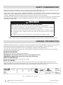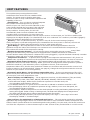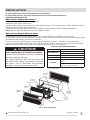
1
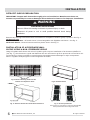
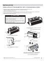
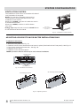
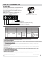
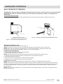
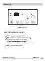
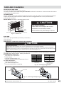
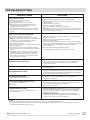
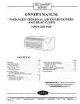
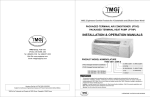
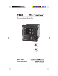
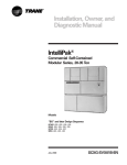
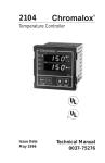
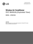
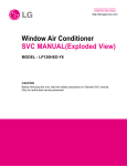
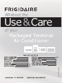
66129907342 (Dec.2010)
SAFETY CONSIDERATIONS
Recognize safety information. This is the safety-alert symbol . When you see this symbol on the unit
and in instructions or manuals, be alert to the potential for personal injury.
Understand these signal words: DANGER, WARNING, and CAUTION. These words are used with the
safety-alert symbol. DANGER identifies the most serious hazards which will result in severe personal injury
or death. WARNING signifies hazards which could result in personal injury or death.
CAUTION is used to identify unsafe practices which may result in minor personal injury or product and
property damage. NOTE is used to highlight suggestions which will result in enhanced installation,
reliability, or operation.
! ! WARNING
WARNING
PERSONAL INJURY AND/OR PROPERTY DAMAGE HAZARD
Failure to follow this warning could result in personal injury, death and/.or property damage.
For your safety, the information in this manual must be followed to minimize the risk of fire or explosion,
electric shock, or to prevent property damage, personal injury, or loss of life.
l
This unit must be properly installed in accordance with the Installation Instructions before it is used.
l
Immediately repair or replace all electric service cords that have become frayed or otherwise
damaged.
l
Unplug or disconnect the unit at the fuse box or circuit breaker before making any repairs.
NOTE: We strongly recommend that any servicing be performed by a qualified professional.
GENERAL INFORMATION
Frigidaire package terminal air conditioners and heat pumps provide a high standard of quality in performance,
workmanship, durability and appearance as they heat and cool the occupied air space year round.
This manual provides information for ease of installation, operation and maintenance.
All models are designed for through--the--wall installation. Separate installation instructions are included
with all accessory components.
BEFORE YOU BEGIN
Read these instructions completely and carefully.
IMPORTANT: Save these instructions for local inspector's use.
IMPORTANT: Observe all governing codes and ordinances.
NOTE TO INSTALLER
Be sure to leave these instructions with the owner.
NOTE TO OWNER
Keep these instructions for future reference. Be sure to write down the model and serial number on the
space provided on the product registration card. The model and serial number can be located on the serial
number plate attached to the unit. These numbers are required for service. (See Fig. 1.)
PACKAGED TERMINAL
AIR CONDITIONER
MODEL:
ENG: 0
ELECTRICAL
VOLTS
Hz,
PH.
COOLING DATA
BTU-
ELECTRIC HEATING DESIGN PRESSURE
BTULOWPSIG
EERAMPSWATTS-
AMPSWATTS-
HIGH- PSIG
R410AOZ
Energy
Performance
Rendement
Energetique
Warning:Use on Single Outlet Circuit Only
Made in China
SERIAL No.:
IK00700001
DATE: 03/11
PACKAGED TERMINAL AIR CONDITIONER
FOR SERVICE
UL FILE NUMBER:SA33529
CALL
ELECTROLUX HOME PRODUCTS FRIGIDAIRE
1-866-942-1567
Charlotte, NC USA
Fig. 1 – Sample Data Information Plate
2
2010 Electrolux Home Products, Inc.
All rights reserved.
UNIT FEATURES
This unit has many exciting features which
are different from those found on standard PTAC
models. The owner must be familiar with these
features in order to fully understand the operation and
capability of the unit.
Intelligence -- Your unit has an on board computer
that utilizes real time diagnostics to prolong
the life of your unit. There is an LED indicator on the
control board, behind the front panel, that will flash
an error code if the unit has detected some kind of
faulty condition. In many cases, the unit will
Fig. 2
automatically clear the fault condition and continue
operating with no interruption. In some cases, the
condition cannot be cleared and the unit will require service. In those cases, an “Fx” failure mode will be
displayed on the digital display. For a detailed list of all error codes and “Fx” conditions, see Table 5 (page12) Status LED Indicator Definitions for further details.
Memory -- Your unit also has memory. If power is lost, all of the control settings (setpoint,
mode, fan speed, on/off and configuration) are remembered. So when power is restored, the unit will
start back up in the mode (and configuration) it was in, when power was lost.
Quiet Design -- Not only does the unit have 2 fan motors and a tangential blower wheel for
optimum sound, the indoor fan will always run a minimum of 10 seconds before the compressor, to
help reduce the sound of the compressor starting.
Random Compressor Restart -- To help prevent power surges after a power outage ( many PTACs
starting at the same time), the compressor is equipped with a 2 minute 45 second to 3 minute 15
second random restart delay feature. Whenever the unit is plugged in, or power has been restarted, a random
compressor restart will occur to help avoid power surges.
Compressor Protection -- To prevent short cycling of the compressor and maximize it's life, there is a
random start--up delay of 3 minutes on the compressor and a minimum compressor run time of 3 minutes.
Automatic Room Freeze Protection -- This protection feature will automatically ensure the indoor
temperature does not fall below freezing. When your PTAC is configured for freeze protection (which is
the default condition), then whenever power is supplied to the unit, if the unit senses
temperature below 40°F, the fan motor and electric heater are turned on and will warm the room to 50°F.
Freeze protection can be switched off (please see page 9), change the configuration switch to turn the
feature off (see section on unit configuration).
Automatic Quick Warm--Up (for heat pump models only) -- If the room temperature falls to 5°F
below the set point temperature, the reverse cycle heat is shut off and the electric strip heat is turned on
for one cycle, until room temperature rises.
Dual-8 Display and LED Display -- Two 8-segment nixie tubes, 13 LED indicators (They are HIGH,
MED, LOW, AUTO, COOL, FAN, HEAT, ON/OFF, SETOPINT, INDOOR, STATUS and TIMER)
1. Mode indicator display: When the air conditioner operates in a certain mode, the
corresponding mode indicator will be lit;
2. The ON/OFF indicator is in green when the controller is ON and in red when controller is OFF.
3. Fan speed display: When air conditioner operates at high, medium, low or auto fan speed, the
corresponding indicator will be lit.
4. Dual-8 display: Ambient temperature can also be displayed in cooling and heating modes through
setting the keypad. Under cooling or heating mode, the dual-8 will display the set temperature
(the dual-8 will display indoor ambient temperature under fan mode).
5. If the display data has three bits, the dual-8 will display “ten's digit”+ “unit's digit” at first and
then display “BLANK”+ “hundred's digit”.
Fan Configure for Optimization of Selected Application -- The unit can be optimized to selected
application by configuring the fan to run in continuous mode or cycle on and off with the compressor and
electric heater (can be different for both heating and cooling modes). In cycle mode, the fan will continue to
run after the compressor or electric heater stops in order to blow off any residual heat or cool left on coil.
2010 Electrolux Home Products, Inc.
All rights reserved.
3
INSTALLATION
Proper installation is the responsibility of the installer.
Product failure due to improper installation is not covered under Warranty.
CHASSIS INSTALLATION
When units are shipped with a sleeve:
1.Remove shipping tape if they are applied.
2.Remove front panel. See Fig.10.
3.Unscrew four screws which connect the main unit with sleeve. The screws location can be referred to Fig.11.
4.Pull out the unit from the wall sleeves.
5.Install sleeve into the wall (please see Installation Instructions of PTAC Sleeve for details).
Note: We recommend always to use a Frigidaire sleeve.
When units are shipped without a sleeve:
In applications where unit is a replacement, it is recommended that a Frigidaire sleeve be used.
Your product can retrofit General Electric, Amana, Trane, and Friedrich sleeves/grilles (be sure outdoor grille
is installed on the sleeve). See Table 3 for details.
For any sleeve retrofit applications, be sure that the foam seals (factory - installed on the tube sheets)
provide a good seal between the grille and outdoor coil tube sheets. These foam seals provide a barrier that
stops air from the inside mixing with air on the outside (known as air recirculation).
Table 3—Retrofit Wall Sleeves
!
CAUTION
! CAUTION
Manufacturer
UNIT DAMAGE AND/OR OPERATION HAZARD
Failure to follow this caution may result in equipment
damage or improper operation.
For retrofit applications, foam seals on outdoor coil
tube sheets must make a seal between the coil and
the grille or loss of performance and premature
damage to the major components can result.
General Electric
Amana
Trane
Friedrich
Wall Sleeve Part Number
Metal Sleeve RAB71
Plastic Sleeve RAB77
Metal Sleeve WS900B
Metal Sleeve SLV149
T---Series Metal 111/2---in. Deep Wall
Sleeve*
Standard Depth Wall Sleeve
16 X 42 X 133/4---in. PXWS
* FR-SLEEVE-EXT accessory is required for retrofit into Friedrich
(T - Series) wall sleeves.
COIL TUBE
SHEETS
OUTDOOR
ORIFICE
WIRE SCREEN
DISCHARGE
GRILLE
INDOOR-AIR
INLET
FILTERS
ACCESSOR
OUTDOOR
GRILLE
ACCESSORY
WALL
SLEEVE
INDOOR
COIL
FR ONT
PANEL
2010 Electrolux Home Products, Inc.
Fig. 3
BASEPAN
Unit Components
All rights reserved.
5
INSTALLATION
RETROFIT SLEEVE PREPARATION
IMPORTANT: Inspect wall sleeve thoroughly prior to installation. Manufacturer does not
assume responsibility for costs or damages due to defects in sleeve or for improper installation.
! !WARNING
WARNING
ELECTRICAL SHOCK HAZARD
Failure to follow this warning could result in personal injury or death.
Disconnect all power to unit to avoid possible electrical shock during
installation.
Remove any existing foam baffles that are installed on competitive outdoor grille, if present. See Fig. 4.
GE Sleeves Only
GE Metal Wall Sleeve - GE metal sleeve is interchangeable with Frigidaire wall sleeve. See Fig. 5.
GE Plastic Sleeve - Remove bottom seal from plastic sleeve. See Fig. 6.
INSTALLATION OF A FRIGIDAIRE WALL
SLEEVE USING A NON- FRIGIDAIRE GRILLE
Using a Frigidaire wall sleeve with a non-Frigidaire grille requires installation of an Accessory Baffle Kit
(see Fig. 7), which ensures a good seal between the unit and exterior grille to prevent air recirculation. Air
recirculation is a large contributor to performance loss and premature damage to major components.
Notes: Frigidaire stamped grille is interchangeable with GE'S.
BAFFLES
Fig.4–Remove Existing Outdoor Grille
Baffles on Competitive Grille
Fig.5-GE Metal Sleeve
SLEEVE
BOTTOM SEAL
Fig. 6 – Remove Bottom Seal From GE Plastic Sleeve
Fig. 7–Accessory Baffle Kit
Note: Contact your units supplier to get the kit, the actual baffle
kit may look different from the image shown above.
6
2010 Electrolux Home Products, Inc.
All rights reserved.
INSTALLATION
INSTALLATION OF A FRIGIDAIRE PTAC INTO A FRIGIDAIRE WALL SLEEVE
1. Carefully remove shipping tape from the front panel and vent door. See Fig. 8.
2. Remove shipping screw from the vent door, if present. See Fig. 9.
3. Remove front panel. See Fig. 10.
4. Lift unit level and slide unit into wall sleeve until foam seal rests firmly against front of wall sleeve.
5. Secure with four screws (supplied) through the unit flange holes. See Fig. 11.
6. Reinstall front panel. See Fig. 12.
!
! CAUTION
CAUTION
UNIT DAMAGE HAZARD
Failure to follow this caution may result in equipment
damage or improper operation.
Failure to remove shipping tape and screw will prevent
fresh air vent door from opening and may result in
damage to vent door cable
Pull out at the bottom to release it from the tabs
(1). Then lift up (2).
Fig. 10 – Removing Front Panel
Shipping
tape
Fig. 8 – Shipping Tape Location
Remove shipping
screw if present
Fig. 11 – Securing Unit
Fig. 9 – Shipping Screw Location
Place tabs over top rail (1). Push Inward at
bottom until panel snaps into place (2).
Fig. 12 – Replacing Front Panel
2010 Electrolux Home Products, Inc.
All rights reserved.
7
SYSTEM CONFIGURATION
VENTILATION CONTROL
The ventilation control lever is located at left side of
unit, behind the front panel.
NOTE: The vent door shipping screw must be
removed before using vent control lever. See
Installation Instructions.
When set at CLOSE, only the air inside the room is
circulated and filtered.
When set at OPEN, outdoor air will be drawn
into room.
Energy Tip: Keep the vent control at CLOSE. Room
air will be filtered and circulated.
Open
Vent Control
(Pull lever through label
to operate.)
Close
Fig. 13 – Ventilation Control Location
ADJUSTING AIR DIRECTION FOR DUCTED INSTALLATIONS ONLY
To adjust air direction:
1. Remove front panel. See Fig. 10.
2. Remove louver screws that hold louver insert in place (from back side of front panel). See Fig. 14.
3. Turn louver insert and rotate 180°. See Fig. 18.
4. Replace louver insert.
5. Replace screws and front panel.
NOTE: Upward air direction should only be used on ducted installations.
Louver screws
Louver screws
Fig. 14 – Backside of Front Panel
Air discharge outward (Default)
Air discharge upward
Fig. 15 – Adjusting Louvers
8
2010 Electrolux Home Products, Inc.
All rights reserved.
SYSTEM CONFIGURATION
DIP SWITCHES
Auxiliary dip switch controls are located behind the front
panel, through an opening below the control panel.
To access, remove front panel. See Fig. 10.
Dip switches are accessible without opening the
control box. Unit must be powered OFF to effectively
change their status.
Factory settings for dip switches will be in the
DOWN position. See Table 4 - Dip Switch Functions
for functions of each dip switch position.
Dip Switches
Fig.16 –Dipswitch Location on Unit
Dipswitch
Up
Down
Freeze guard
Setpoint Limit 2
Setpoint Limit 1
Fan CON/CYC for cooling/Energy Saver: Cooling
Fan CON/CYC for heating/Energy Saver: Heating
Wall Thermostat enable
Electric heat only (for Heat Pumps)
Fig.17 –Dip Switches
Table 4—DIP SWITCH FUNCTIONS
No,
UP
DOWN
DEFAULT
REMARKS
1
Electric Heat Only
Heat Pump
DOWN
For Heat Pump unit only
2
Wall Thermostat Enable
Control Panel Enable
DOWN
3
Fan Continuous Run for Heating
Fan Cycle for Heat
DOWN
4
Fan Cycle for Cool
Fan Continuous Run for Cooling
DOWN
5*6
UP*UP
68---75℉
20---24℃
UP*DOWN
63---80℉
18---28℃
DOWN*UP
65---78℉
19---26℃
DOWN*DOWN
61---86℉
16---30℃
(full range)
DOWN*DOWN
61---86℉
16---30℃
Two configurations (5*6)
Combine to select set
point range.
When set point limit set,
display always shows
full range.
7
Freeze Guard Disable
Freeze Guard Enable
DOWN
1.Electric Heating Only / Emergency Heat (For Heat Pump Units Only)
This setting is typically used for Emergency Heating.
2.Wall Thermostat Enable
A wired wall thermostat can be connected to the unit. The dip switch must be adjusted accordingly in order to
allow the wall thermostat control of the unit. When in wall thermostat mode, the control panel will be disabled.
3*4.Energy Saver Dip Switches
Allows the fan to operate in continuous or cycle modes while the unit is in heating or cooling mode
(continuous or cycle):
CON (Continuous)
Allows fan to run continuously, circulating air even when the temperature setting has been satisfied.
CYC (Cycle)/Energy Saver
This setting allows the fan to cycle on and off with the compressor or electric heater. The fan stops a
short time after the temperature setting is satisfied.This is the most efficient mode for electrical usage.
5*6.Setpoint Temperature Limits
Provides a range of temperature control.
7.Room Freeze Protection
If the unit senses a room temperature below 40°F, the fan motor and electric strip heat will turn on and
warm the room to 50°F. The fan stops a short time after the temperature is satisfied.
2010 Electrolux Home Products, Inc.
All rights reserved.
9
SYSTEM CONFIGURATION
KEYPAD CONFIGURATION
Keypad Configuration
You can customize your unit additionally using the keypad configuration options.
To enter Keypad configuration
Connect the unit to power. Press and hold the "fan speed " and the "V " for 5 continuous seconds, within
30 seconds of the unit being powered up. If the unit has had power for more than 30
continuous seconds, keypad configuration cannot be made.
To scroll through the Keypad Configuration Options
Press and release the "fan speed" to select the keypad configurations.
The stored value will be displayed.
To modify configuration settings
V
Press and release the Setpoint " " or Setpoint " V " buttons.
To exit Keypad Configuration
Keypad Configuration will end on its own 30 seconds after the last button press or when the "mode" on the
Keypad is pressed.
There are 4 configuration options˖
1. Fahrenheit/Celsius Display Switch:
Change between degrees Fahrenheit and Celsius on the display. An “F” indicates Fahrenheit display and
'C' indicates Celsius. Default is degrees “F”.
2. Indoor Air Temperature Sensor Biasing for Cooling mode:
Sometimes known as an anticipator, the air temperature sensor bias is used to adjust the room air
temperature reading when in cooling mode. (Not normally required.)
3. Indoor Air Temperature Sensor Biasing for Heating mode:
Sometimes known as an anticipator, the air temperature sensor bias is used to adjust the room air
temperature reading when in heating mode. (Not normally required.)
4. Indoor Temperature Display:
Change between showing the setpoint or desired temperature during heating and cooling modes (SP)
or displaying the actual room temperature during heating and cooling modes (AA). SP mode is the
default mode.
If SP is selected the desired setpoint temperature will be displayed during heating and
cooling modes, regardless of what the actual temperature is in the room.
If AA mode is selected, the room temperature will be displayed during heating,
cooling and fan only modes.
— If the mode button has been changed to either heating or cooling modes, setpoint will be displayed
for 10 seconds. After the 10 seconds, the room temperature will again be displayed.
— If the on/off button is depressed (when the unit is off ) and the last mode was either cooling or
heating mode, the setpoint will be displayed for 10 seconds before displaying room temperature.
— During heating and cooling modes, if either the up or down setpoint key is depressed, the display
will show the setpoint for 10 seconds. Then the room temperature will be displayed again.
Switchover between Emergency Auto Cooling Allowed and Emergency Auto Cooling Rejected:
V
Press "
" or " V " to switch between the display of Emergency Auto Cooling
Allowed and Emergency Auto Cooling Rejected.
Emergency Auto Cooling Allowed: the diode displays CA.
Emergency Auto Cooling Rejected: the diode displays CD.
Auto cooling operation:
o
If this function is activated and room temperature reaches 85 F while the unit is in
the "STOP" setting, the unit will automatically start in air conditioning operation and will
o
shut off when the room temperature reach 80 F.
10
2010 Electrolux Home Products, Inc.
All rights reserved.
AUXILIARY CONTROLS
WALL THERMOSTAT TERMINAL
IMPORTANT: Only trained, qualified personnel should access the electrical panel on unit and install
electrical accessories. Please contact your local electrical contractor, dealer, or distributor for
assistance.
Thermostat Wire Routing
Thermostat wire is field supplied. Recommended wire gauge is 18 to 20 gauge solid thermostat wire.
R W Y O Gh Gl C
THERMOSTAT WIRE ROUTING
(UNDER SLEEVE, BEHIND FRONT PANEL)
Fig. 19 –Terminal Connector Removal and Replacement
Fig. 18 – Proper Wire Routing Beneath Unit
Wiring Thermostat To Unit
Wire wall thermostat input as defined in Fig. 21.
NOTE: Terminal connector can be removed and replaced to simplify the wiring. See Fig.19 .
NOTE: For heat pump models, anytime there is a second-stage call for heating from the wall
thermostat, the unit will automatically switch over to electric heating.
Install Thermostat Wiring
1. Check to be sure power to unit is disconnected.
2. Pull terminal connector to remove
NOTE: Terminal connector can be removed and replaced to simplify thermostat wiring.
3. Connect wires from the thermostat to terminals on unit terminal connector.
4. Reinstall terminal connector.
5. Ensure that unit is configured for wall thermostat enable.
6. Replace control panel label with control panel guard.
7. Restore power to unit.
NOTE: Refer to thermostat installation instructions for details on installing wall thermostat.
NOTE: For thermostats that have two fan speed output (Low fan or Hi fan), the fan speed is determined by
how the terminal connector is wired. If Low fan is desired, wire the GL output from the thermostat to GL on
the unit's terminal block. If Hi fan is desired, wire the GH output from the thermostat to GH on the unit's
terminal block.
NOTE: After proper installation, if your thermostat is not working properly, refer to the Trouble Shooting
section on page 17.
2010 Electrolux Home Products, Inc.
All rights reserved.
11
AUXILIARY CONTROLS
TERMINAL CONNECTIONS
The wall thermostat terminal block is located behind the front panel and is easily accessible on front of
control panel.
Energy
management
(24VAC in)
Common
R
W
Y
TYPICAL WALL THERMOSTAT
O See Note 1
GH
GL
C See Note 2
STATUS LED
NOTES:
1. Use terminal “O” for heat pump connection only.
2. Terminal “C” (common) is typically only required
for digital thermostats.
TERMINAL BLOCK
Energy Management
Terminal Connections
Wall Thermostat
Terminal Connections
Fig.20– Terminal Connector and Status LED Location
! CAUTION !
CAUTION
UNIT DAMAGE HAZARD
Failure to follow this caution may result in equipment damage
or improper operation.
Improper wiring may damage unit electronics. Common
busing is not permitted. Damage or erratic operation may
result.
TERMINAL
DESIGNATION
R
24 VAC
W
Electric Heat
Y
Compressor
O
Reversing Valve
GH
High Fan
GL
Low Fan
C
Common
NOTE: Any incorrect input combinations will be captured as
thermostat wiring failures and will light the STATUS LED
indicator on main board (see Intelligent Self - Checking
Control section)
Fig.21–Wiring Connections
ENERGY MANAGEMENT INPUT (FRONT DESK CONTROL)
The controller can handle a switch signal from remote energy management input, called EM signal or front
desk control. Input must be 24VAC. If system receives a 24VAC signal, it will turn unit off; otherwise, the
unit runs in normal control. This function will be disabled under Freeze Guard protection. See Fig. 20 and
Fig. 21 for terminal connections.
INTELLIGENT SELF-CHECKING CONTROL
Your Frigidaire PTAC has a computer on-board that continuously checks key components of the unit to ensure
they are operating properly. Under normal operation, unit status indicator (STATUS, on main PCB), light is
steadily ON. If there is a major problem, the unit will shut down and display a diagnostic failure code on
the unit's display. If it is a minor error and the unit can correct it by itself, the diagnostic code
will be flashed on the status LED that can easily be seen when the front panel is removed (see Fig.23).
Failure STATUS codes are defined in the table below
Table 5—STATUS LED Indicator Definitions
1
2
3
4
5
6
7
8
9
12
Indoor air temp sensor open/short
Indoor coil sensor open or short
Outdoor coil sensor open/short
Freeze Guard protection
Indoor coil freeze protection
Outdoor coil high temp protection
Defrost (heat pump type)
Indoor coil high temp protection
Thermostat wiring error
8-segment display ‘F1’, with STATUS light flash 1 times and off 3 sec, repeat
8-segment display ‘F2’, with STATUS light flash 2 times and off 3 sec, repeat
8-segment display ‘F4’, with STATUS light flash 3 times and off 3 sec, repeat
8-segment display ‘FP’
STATUS light flash 5 times and off 3 sec, repeat
STATUS light flash 6 times and off 3 sec, repeat
STATUS light flash 7 times and off 3 sec, repeat
STATUS light flash 8 times and off 3 sec, repeat
STATUS light flash 9 times and off 3 sec, repeat
2010 Electrolux Home Products, Inc.
NOTE: When status
light is flashing, it will
be ON for 1 seconds
and OFF for another
1 seconds.
All rights reserved.
"ON-OFF"
unit.
"mode"
V
" "
4. "V"
5. "fan speed" ˖It is used for setting high, medium, low or auto fan speed. The
corresponding LED will be lit when selected.
6. "timer" ˖It is used for setting timer function.
OPERATION
7. Timer function
(1) Timer ON: When the unit is off, timer ON can be set. Setting range is 0.5~24h. When timer ON
time is reached, the system will operate according to the set mode.
(2) Timer OFF: When the unit is off, timer OFF can be set. Setting range is 0.5~24h. When timer
OFF time is reached, the system will stop operation.
(3) Timer Setting: Press "timer " to set timer function and TIMER icon will be on. The time can be
adjusted by pressing" " or "V" buttons.
The range of timer setting is from 0.5h to 24h.
V
5 seconds after timer setting, the timer function will be activated and TIMER icon will be on.
(4) Timer Preview: When timer function has been set, press "timer" to preview the remaining
time of timer.
(5) If Timer function has been set, turning on/off the unit or power failure will cancel timer setting.
14
2010 Electrolux Home Products, Inc.
All rights reserved.
CARE AND CLEANING
FRONT PANEL AND CASE
Turn unit off and disconnect power supply.
To clean, use water and a mild detergent. DO NOT use bleach or abrasives. Some commercial cleaners
may damage the plastic parts.
OUTDOOR COIL
Coil on outdoor side of unit should be checked regularly. Unit will need to be removed from its sleeve to
inspect dirt build-up that can occur inside of the coil. If clogged with dirt or soot, coil should be
professionally cleaned.
NOTE: Never use a high - pressure spray on coil.
! CAUTION
! CAUTION
UNIT DAMAGE HAZARD
Product failure due to improper care or lack of
maintenance is not covered by warranty.
Coils
Airflow restriction may cause damage to the unit.
Grille
Clean inside and outside of outdoor coils regularly.
Fig. 23 – Outdoor Coil
BASE PAN
Check base pan periodically and clean, if necessary.
AIR FILTERS
IMPORTANT: TURN UNIT OFF BEFORE CLEANING
!
CAUTION
UNIT DAMAGE HAZARD
Product failure due to improper care or lack of maintenance is not covered by warranty.
Do not operate unit without filters in place. If a filter becomes torn or damaged, it should be replaced immediately.
Operating without filters in place or with damaged filters will allow dirt and dust to reach indoor coil and reduce cooling,
heating, airflow and efficiency of unit. Airflow restriction may cause damage to unit.
To maintain unit efficiency clean the filters at least every 30 days (or sooner depending on application).
Clogged filters reduce cooling, heating and airflow.
Keeping filters clean will:
Decrease cost of operation.
Save energy.
Prevent clogged indoor coil.
Reduce risk of premature component failure.
To Clean Air Filters:
Vacuum off heavy soil.
Clogged filter Dirty filterGreatly reduces cooling,
Needs cleaning
Run water through filters.
heating and airflow.
Dry thoroughly before replacing.
Fig. 24 – Identifying Clogged Filter
2 Air filters
Pull up
Push down
Fig. 25 – Removing and Replacing Air Filter
Removing Air Filter
2010 Electrolux Home Products, Inc.
Replacing Air Filter
All rights reserved.
15
PREVENTATIVE MAINTENANCE
Preventative maintenance is essential to proper unit operation, efficiency and longevity.
To ensure equipment operates properly, it must be properly maintained. Equipment operation should be
checked and verified several times during each year. During regular unit inspection and maintenance,
follow the guidelines below:
Clean both sides of outdoor coil. (Never use high pressure spray on coils.)
Clean basepan and outdoor vent filter.
Clean outdoor orifice and fan.
Clean indoor coil. (Never use high pressure spray on coils.)
Clean indoor fan, wire screen and front panel.
Clean or install new indoor - air inlet filter(s).
Clean wall sleeve and outdoor grille.
Inspect cord and receptacle.
Secure electrical connections.
Ensure front panel is properly mounted and not damaged.
Ensure wall sleeve is installed properly.
Ensure heat and cool cycles operate properly.
16
2010 Electrolux Home Products, Inc.
All rights reserved.
TROUBLESHOOTING
POSSIBLE CAUSES
SOLUTIONS
UNIT DOES NOT START
Unit may have become unplugged
Fuse may have blown
Circuit breaker may have been tripped
Unit may be off or in wall thermostat mode.
Check section on dipswitch settings to verify
dipswitches are set properly.
Unit may be in a protection or diagnostic failure
mode. See section on Intelligent Self---checking
Control.
Check that plug is plugged securely in wall receptacle.
Note: Plug has a test/reset button on it. Make sure that the plug
has not tripped.
Replace the fuse. See Note 1.
Reset circuit breaker. See Note 1.
Turn unit on (bottom right button on keypad).
Note: If the unit turns on, the LED will be green. If the unit is off,
the LED will be red. If there is no LED on, there is a problem with
power or damage to the control.
UNIT NOT COOLING/HEATING ROOM
Unit air discharge section is blocked
Temperature setting is not high or low enough.
Note: Set point limits may not allow the unit to heat
or cool the room to the temperature desired.
Check section on dipswitch settings.
Unit air filters are dirty.
Room is excessively hot or cold when unit is started.
Vent door left open.
Unit may be in a protection or diagnostic failure
mode. Check section on Intelligent Self---checking
Control.
Compressor is in time delay. There is a protective
time delay (approx. 3 minutes) on starting the
compressor after a power outage (or restarting
after it has been turned off ), to prevent tripping
of the compressor overload.
DISPLAY HAS STRANGE
NUMBERS/CHARACTERS ON IT
Make sure that curtains, blinds or furniture are not restricting or
blocking unit airflow.
Reset to a lower or higher temperature setting.
Remove and clean filters.
Allow sufficient amount of time for unit to heat or cool the room.
Start heating or cooling early before outdoor temperature, cooking
heat or gatherings of people make room uncomfortable.
Close vent door.
Check dipswitch settings for desired comfort.
Wait approximately 3 minutes for compressor to start
The unit may be in a diagnostic condition. Check Intelligent SelfChecking Control section to determine if unit has had a failure.
The unit may be set for °C(instead of °F), see the keypad
configuration section
UNIT MAKING NOISES
Clicking, gurgling and whooshing noises are normal during
operation of unit.
WATER DRIPPING OUTSIDE
If a drain kit has not been installed, condensation runoff during
very hot and humid weather is normal. See Note 2. If a drain kit has
been installed and is connected to a drain system, check gaskets
and fittings around drain for leaks and plugs.
WATER DRIPPING INSIDE
Wall sleeve is not installed level
ICE OR FROST FORMS ON INDOOR COIL
Low outdoor temperature
Dirty filters
COMPRESSOR PROTECTION
Power may have cycled, so compressor is in a
restart protection
Wall sleeve must be installed level for proper drainage of
condensation. Check that installation is level and make any
necessary adjustments.
When outdoor temperature is approximately 55 °F or below, frost
may form on the indoor coil when unit is in Cooling mode. Switch
unit to FAN operation until ice or frost melts.
Remove and clean filters.
Random Compressor restart-Whenever the unit is plugged in,
or power has been restarted, a random compressor restart will
occur. After a power outage, the compressor will restart after
approximately 3 minutes.
Compressor Protection-To prevent short cycling of the
compressor, there is a random startup delay of 3 minutes and a
minimum compressor run time of 3 minutes.
NOTES:
1. If circuit breaker is tripped or fuse is blown more than once, contact a qualified electrician.
2. If unit is installed where condensation drainage could drip in an undesirable location, an accessory drain kit should be
installed and connected to drain system.
2010 Electrolux Home Products, Inc.
All rights reserved.
17
SAFETY PRECAUTIONS
SAFETY PRECAUTIONS
DANGER! Avoid Serious Injury or Death
1. Do not attempt to install air conditioner by yourself.
2. This air conditioner contains no user-serviceable parts. Always call an authorized
Electrolux servicer for repairs.
3. When moving the air conditioner, always call an authorized Electrolux servicer for
disconnection and re-installation.
4. Do not insert or place fingers or objects into the air discharge area in the unit.
5. Do not start or stop the air conditioner by unplugging the power cord or turning
off the power at the electrical box.
6. Do not cut or damage the power cord.
7. If the power cord is damaged it should only be replaced by an authorized
Electrolux servicer.
8. In the event of a malfunction (sparks, burning smell, etc.) immediately stop the
operation, disconnect the power cord, and call an authorized Electrolux servicer.
9. Do not operate the air conditioners with wet hands.
10. Do not pull on the power cord.
11. Do not drink any water that is drained from the air conditioners.
CAUTION! Avoid Injury or damage to the unit or other property
1. Provide occasional ventilation during use. Do not direct airflow at fireplaces or
other heat related sources as this could cause flare ups or make units run
excessively.
2. Do not place containers containing water on unit.
3. Turn off the air conditioner at the power source when it will not be used for an
extended period of time.
4. Periodically check the condition of the unit’s installation base for any damage.
5. Do not apply heavy pressure to the radiator fins of the units.
6. Operate the unit with air filters in place.
7. Do not block or cover the intake grille, discharge area and outlet ports.
8. Ensure that any electrical/electronic equipment is one yard away from the unit.
9. Do not use or store flammable gases near the unit.
INSTALLATION WARNINGS
1. Carefully read the installation section of this manual before beginning.
2. Follow each step as shown.
3. Observe all local, state, and national electrical codes and by qualified, licensed,
authorized personnel only.
4. Pay attention to danger and safety notices.
18
2010 Electrolux Home Products, Inc.
All rights reserved.
MAJOR APPLIANCE LIMITED WARRANTY
Your appliance is covered by a limited two-year warranty and a limited 3-5 year warranty on the sealed system (the compressor,
condenser, evaporator and tubing). For two years from your original date of purchase, Electrolux will pay all costs for repairing or
replacing any parts of this appliance that prove to be defective in materials or workmanship when such appliance is installed,
used and maintained in accordance with the provided instructions. From the third to the fifth year from your original purchase
date, Electrolux will repair or replace any parts in the Sealed Refrigeration System (compressor, condenser, evaporator and tubing)
that prove to be defective in materials or workmanship. In years 3-5, the consumer will be responsible for diagnostic, labor and
parts costs as well as any removal, transportation and reinstallation expenses which are incurred during service on components
other than those covered under the Sealed Refrigeration System 5-year warranty.
Exclusions
This warranty does not cover the following:
1. Products with original serial numbers that have been removed, altered or cannot be readily determined.
2. Product that has been transferred from its original owner to another party or removed outside the USA or
Canada.
3. Rust on the interior or exterior of the unit.
4. Products purchased "as-is" are not covered by this warranty.
5.
Service calls which do not involve malfunction or defects in materials or workmanship,
or used other than in accordance with the provided instructions.
6. Service calls to correct the installation of your appliance or to instruct you how to use your appliance.
7. Expenses for making the appliance accessible for servicing, such as removal of trim, cupboards, shelves,
etc., which are not a part of the appliance when it is shipped from the factory.
8. Service calls to repair or replace appliance light bulbs, air filters, water filters, other consumables, or knobs,
handles, or other cosmetic parts.
9. Surcharges including, but not limited to, any after hour, weekend, or holiday service calls, tolls, ferry trip
charges, or mileage expense for service calls to remote areas, including the state of Alaska.
10. Damages to the finish of appliance or facility incurred during installation, including but not limited to floors,
cabinets, walls, etc.
11. Damages caused by: services performed by unauthorized service companies; use of parts other than
genuine Electrolux parts or parts obtained from persons other than authorized service companies; or external
causes such as abuse, misuse, inadequate power supply, accidents, fires, or acts of God.
DISCLAIMER OF IMPLIED WARRANTIES; LIMITATION OF REMEDIES
CUSTOMER'S SOLE AND EXCLUSIVE REMEDY UNDER THIS LIMITED WARRANTY SHALL BE PRODUCT REPAIR OR
REPLACEMENT AS PROVIDED HEREIN. CLAIMS BASED ON IMPLIED WARRANTIES, INCLUDING WARRANTIES OF
MERCHANTABILITY OR FITNESS FOR A PARTICULAR PURPOSE, ARE LIMITED TO ONE YEAR OR THE SHORTEST
PERIOD ALLOWED BY LAW, BUT NOT LESS THAN ONE YEAR. ELECTROLUX SHALL NOT BE LIABLE FOR
CONSEQUENTIAL OR INCIDENTAL DAMAGES SUCH AS PROPERTY DAMAGE AND INCIDENTAL EXPENSES
RESULTING FROM ANY BREACH OF THIS WRITTEN LIMITED WARRANTY OR ANY IMPLIED WARRANTY. SOME
STATES AND PROVINCES DO NOT ALLOW THE EXCLUSION OR LIMITATION OF INCIDENTAL OR CONSEQUENTIAL DAMAGES, OR LIMITATIONS ON THE DURATION OF IMPLIED WARRANTIES, SO THESE LIMITATIONS
OR EXCLUSIONS MAY NOT APPLY TO YOU. THIS WRITTEN WARRANTY GIVES YOU SPECIFIC LEGAL RIGHTS.
YOU MAY ALSO HAVE OTHER RIGHTS THAT VARY FROM STATE TO STATE.
If You Need Keep your receipt, delivery slip, or some other appropriate payment record to establish the warranty period
Service
should service be required. If service is performed, it is in your best interest to obtain and keep all receipts.
Service under this warranty must be obtained by contacting Electrolux at the addresses or phone
numbers below.
This limited warranty only applies in the USA and Canada. In the USA, your appliance is warranted by Electrolux Major Appliances
North America, a division of Electrolux Home Products, Inc. In Canada, your appliance is warranted by Electrolux Canada Corp.
Electrolux authorizes no person to change or add to any obligations under this warranty. Obligations for service and parts under
this warranty must be performed by Electrolux or an authorized service company. Product features or specifications as described
or illustrated are subject to change without notice.
USA
1.866.942.1567
Electrolux Major Appliances-North America
10200 David Taylor Drive
Charlotte NC 28262
2010 Electrolux Home Products, Inc.
Canada
1.866.942.1567
Electrolux Canada Corp.
5855 Terry Fox Way
Mississauga, Ontario, Canada
L5V 3E4
All rights reserved.
19