1
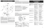
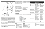
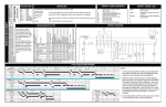
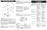
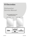
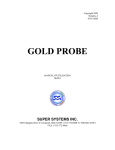
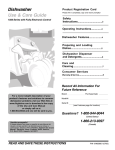
Press desired cycle and/or option pad. The indicator lights will change. Press
START/CANCEL within 15 seconds to begin cycle.
DRYING------------- Drying portion of cycle.
SANITIZED--------- The SANITIZED criteria has been met. Indicator light will switch off when door is opened.
CLEAN--------------- Shows completion of cycle. Indicator light will switch off when door is opened.
Press START/CANCEL. Dishwasher will drain for 90 seconds, then
shut off.
OPTION LED’s Flashing- When ALL LED’s are flashing this indicates power failure has occured. Press START/CANCEL pad
and reslect desired options and cycles.
Press and hold the RINSE HOLD or NO HEAT DRY pad for 3 seconds.
To unlock, press and hold the RINSE HOLD or NO HEAT DRY pad for 3 seconds.
WATER/SERVICE TEST
75
0
1
0
1
0
1
0
0
0
0
6
Wash/Heat/Det. Disp.
60
0
1
0
1
1
1
0
0
0
0
7
Drain
90
0
0
1
0
0
1
0
0
0
0
8
Dry
90
0
0
1
x
0
0
0
0
1
0
0
0
0
0 0
0
0
1
0
1
End State
X - denotes selectable option
Clean LED stays on until door is opened or cycle is started
CYCLE SELECTION OPTIONS
*TURBIDITY SENSOR/
THERMISTOR
P3- 7
W
*SOME MODELS
Wash/Heat
W
5
W
0
NEUT
0
P1
0
120VAC
60HZ
1
BK
1
L1 BK
1 0
P3- 6
0
BK
0
Pause
DOOR
SWITCH
0.4 0
4
P2- 3
0
R
0
P2- 2
0
W
1
P2- 1
1
BK
1
P8
1
W
0
HEATER
1
HI-LIMIT
THERMOS T AT R
0
P3- 3
60
PK
Wash/Heat/Det. Disp.
WATER VALVE
3
FLO AT
SWITCH
0
W
0
P3- 2
0
R-BK
1
*VENT SYSTEM S W
1
ELECTRONIC
CONTROL
BOARD
0
W
0
P2- 5
0
BK
0
P3-10
1
Y
27
*THERMISTO R
Fill
P3- 9
2
Y
0
P3- 4
Clean LED
0
VI O
Drying LED
0
DRAIN MOTO R W
Sanitize LED
1
P3- 5
Washing LED
1
BU
Vent
0 1
W
Heater
0
P- 5
Drain Motor
0
USER INTERFACE SWITCH
Circulation Motor
1
Notes
Water Valve
60
Dispenser
Interval Duration Sec.
Fill/Det. Dispenser
PUMP MOTOR
The dishwasher will then step
through the test cycle per the
chart. Pushing the START/CANCEL
pad will advance the dishwasher
to the next step.
1
Description
While in power failure mode simultaneously press the AIR DRY
and START/CANCEL pads for 1
1
/2 seconds. While in Idle Mode,
simultaneously press HI-TEMP
WASH and START/CANCEL pads
for 6 seconds.
Interval Number
The water/service test, (WST)
is a special function initiated
from the power failure mode
or idle mode.
WIRING DIAGRAM
P3- 1
To cancel
a cycle ----------------
R- Y
To cancel
a cycle ----------------
WASHING---------- Wash portion of cycle.
DISPENSER
To select a new cycle
or option -------------
Close door fully to latch. Press START/CANCEL pad.
Close door fully to latch. Press DELAY START pad to select desired
delay time.
P2- 6
To start ----------------To delay start ---------
BK
BK............Black
BU............Blue
PK............Pink
R..............Red
Viol..........Violet
W.............White
Y..............Yellow
R-Y.........Red/Yellow
R-BK......Red/Black
DISPLAY CODES (LED)
OPERATION
*RINSE AID
LEVEL SENSE
Electronic Series
This information is intended for use by persons having electrical and
P/N: A02841501 Rev.A
mechanical training and a level of knowledge of these subjects generally
Artwork: A02841501 Rev.001
considered acceptable in the appliance repair trade. Electrolux Home
Products North America cannot be responsible, nor assume any liability,
for injury or damage of any kind arising from the use of this Service
Data Sheet.
SERVICE DATA SHEET
COLOR CODE
EXPLODED VIEW OF WASH SYSTEM
Standard Dry Air Flow
When the control advances to the
“dry” portion of the cycle heated,
moist air leaves the dishwasher
through the console vent. Drier air
is then drawn into the unit through
vents at the bottome of the door.
Heat stored in the dishware causes
the water on the dishes to evaporate
into the drier air.
TROUBLE SHOOTING TIPS
This process continues throughout the
drying phase as the heating element is
turned ON and OFF.
WARNING
Personal Injury Hazard
Always disconnect the dishwasher from the electrical power source before adjusting or
replacing components.
Symptom
Dishwasher will not
operate when turned on.
Remedy
1.
2.
Fuse (blown or tripped).
120 VAC supply wiring
connection faulty.
Electronic control board
defective.
No 12 VAC power to
control.
Motor (inoperative).
Door Switch (open
contacts).
Door latch not making
contact with door switch
Touch pad circuit defective.
No indicator lamps
illuminate when START or
OPTIONS are pressed.
1.
3.
Detergent and Rinse
The detergent and rinse aid dispenser
is a one piece component consisting
of a molded detergent cup and a
built-in rinse aid dispenser.
The detergent cup has a spring
loaded cover and the rinse aid
dispenser has a removeable cover.
To re-fill, remove the cap and poor
rinse aid in until the level shows
above the bottom of the cylindrical
opening and the sight gauge changes
appearance. If any is spilled wipe
it up before starting the cycle. The
amount of rinse aid released
Check the Following
4.
can be adjusted by turning the arrow
indicator from one, being the least
amount, to four, being the greatest
amount.
To replace dispenser:
• shut off electricity to dishwasher,
• remove outer door panel assembly,
• disconnect wiring to the actuator,
• remove the six screws,
• remove the dispenser,
• replace and reinstall screws,
• rewire actuator.
5.
6.
7.
8.
9.
Motor (bad bearings).
Motor stuck due to
prolonged non-use.
1.
2.
Replace motor assembly.
Rotate motor impeller.
Motor trips out on
internal thermal
overload protector.
1.
2.
3.
Improper voltage.
Motor windings shorted.
Glass or foreign items in
pump.
1.
2.
3.
Check voltage.
Replace motor/impeller
assembly.
Clean and clear blockage.
Dishwasher runs but will
not heat.
1.
2.
Heater element (open).
Electronic control board
defective.
Wiring or terminal
defective.
Hi-Limit thermostate
defective.
Thermistor failure.
1.
2.
3.
4.
5.
Replace heater element.
Replace control board.
Repair or replace.
Replace thermostat.
Replace turbidity sensor.
Latch mechanism defective.
Electronic control board
defective.
Wiring or terminal
defective.
Broken spring (s).
Defective actuator.
1.
2.
3.
4.
5.
Replace dispenser.
Replace control board.
Repair or replace.
Replace dispenser.
Replace dispenser.
Drain restricted.
Electronic control board
defective.
Defective drain pump.
Blocked impeller.
Open windings.
Wiring or terminal
defective.
1.
2.
3.
4.
5.
6.
Clear restrictions.
Replace control board.
Replace pump.
Check for blockage, clear.
Replace pump assembly.
Repair or replace.
Water supply turned off.
Defective water inlet fill
valve.
Check fill valve screen for
obstructions.
Defective float switch.
Electronic control board
defective.
Wiring or terminal
defective.
Float stuck in “UP” position.
1.
2.
Turn water supply on.
Replace water inlet fill
valve.
Disassemble and clean
screen.
Repair or replace.
Replace control board.
Repair or replace.
Clean float.
Drain hose (high) loop too
low.
Drain line connected to a
1.
2.
Repair to proper 32-inch
minimum height.
Connect to a vented drain.
Detergent allowed to stand
too long in dispenser.
Dispenser wet when
detergent was added.
Detergent cover held closed
or blocked by large dishes.
Improper incoming water
temperature to properly
dissolve detergent.
See “Detergent cover will
not open”.
1.
Instruct customer/user
2.
Instruct customer/user
3.
Instruct customer/user
on proper loading of
dishes.
Incoming water
temperature of 1200F
is required to properly
dissolve dishwashing
detergents.
Tub and Door Seal
5.
Pump Assembly
The assembly is driven by a
synchronous motor. Rotation is in the
counterclockwise direction at 3600RPM.
The motor drives a pump which
supplies 100 percent filtered water
at a rate of approximately 12 GPM to
one spray arm at a time. The spray
arm’s operation is alternated by small
“pauses” of the motor during the wash
cycle.
Draining is accomplished by using a
small separate synchronous drain pump
mounted to the side of the sump. The
drain check valve is located at the
discharge end of the drain pump. The
drain hose is attached by a worm gear
clamp to the discharge end of the drain
pump.
The drain hose must have a loop at
a minimum height of 32 inches
in order to insure proper drainage.
To remove the main circulation
(circ) pump do the following in
sequence: Shut off electricity to the
dishwasher. Disconnect the wiring
harness connections located at the
circ pump’s motor. Remove the two
screws that hold the motor bracket.
Slide the motor bracket away from
the sump. The motor and pump,
now held only by friction against
O-rings, can be pulled out of the
sump.
900 Watt Heater
Refer to the cycle chart on the reverse
side to determine when the heater is
on during the wash cycle. The heater
cycles ON and OFF for brief periods
during the drying cycle.
Voltage checks of the heater
should be made in the dry portion
of the service test mode.
Tub Interior
Short Turn
Electrical
Rating......................................120 Volts, 60Hz
Separate Circuit..15 amp min......- 20 amp max.
Motor (Amps)............................................1.8
Heater Wattage.........................................900
Total Amps (load rated).............................10.0
TempAssure......................................1400F+- 50F
(600C+- 30C) [with outer door in place]
TempBoost........................................1450F+- 50F
(630C+- 30C) Heated Wash/Heated Rinse
Sanitize.............................1500F+- 50F (660C+- 30C)
Hi-Limit Thermostat .......................2000F (930C)
Detergent cover will not
latch or open.
1.
2.
3.
4.
5.
Dishwasher will not
pump out.
1.
2.
3.
4.
5.
6.
Dishwasher will not fill
with water.
1.
2.
3.
4.
5.
6.
7.
Product Specifications
Water Supply
Suggested minimum incoming water
temperature...........................1200F (490C)
Pressure (PSI) min./max...................20/120
Connection..............................3/8” NPT or
3/4” Hose Thread
Consumption (Normal Cycle).......................
4.9 - 9.7 U.S. gal., 18.5 - 36.7
Water valve flow rate (U.S.GPM)..............83
Water recirculation (U.S. GPM)....................
approx. 12
Water fill time...................................87
Replace console assembly.
Replace console assembly.
1.
2.
4.
Line up the center mark on the back of the
seal with the tub top center and press it
into the channel. Move along the channel
left and right periodically pressing the seal
into place without bunching or stretching
it until going around the corners at the
top. Next, place the free ends into the
channel at the bottom left and right by
creating a short turn at the bottom of the
tub channel and ensuring the seal extends
to the locator ridge at the bottom of the
tub (see enlarged portion of the attached
image). Then, press the seal periodically
into place. Finally slide your fingers over
the seal to press it fully in place. When
complete a single face of the seal should
be visible and flush with the edge of the
channel.
8.
9.
3.
4.
5.
Motor hums but will not
start or run.
3.
Mounting Rib
6.
7.
Replace fuse or reset
breaker.
Repair or replace wire
fasteners at dishwasher
junction box.
Replace control board.
Replace control board.
Replace motor/impeller
assembly.
Replace latch assembly.
Replace latch assembly.
2.
Dishwasher water
siphons out.
1.
Detergent left in
dispenser.
1.
2.
2.
3.
4.
5.
3.
4.
5.
6.
7.
4.